Advertisement
Quick Links
Advertisement

Related Manuals for Cuisinart SMK2036AS


Summary of Contents for Cuisinart SMK2036AS
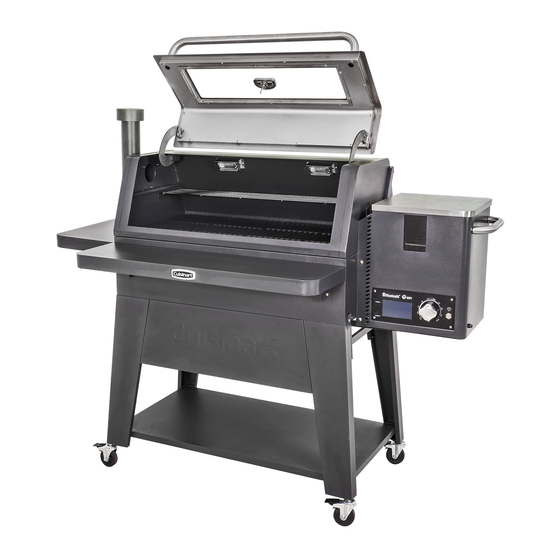
- Page 1 Oakmont Pellet Grill and Smoker ASSEMBLY IN STRUC TIONS Model SMK2036AS...
- Page 2 READ ALL SAFETY WARNINGS & ASSEMBLY INSTRUCTIONS CAREFULLY BEFORE ASSEMBLING OR OPERATING YOUR GRILL. WE RECOMMEND TWO PEOPLE WORK TOGETHER WHEN AS SEM BLING THIS UNIT. The following tools are required to assemble this Cuisinart Oakmont 3-in-1 Pellet Grill: • Phillips Screwdriver • Pliers or Wrench...
- Page 4 Step 1 • Loosen 4 screws. • Attach front legs front panel using keyholes. • Tighten 4 screws. Remove Remove • Remove 8 screws. NOTE: Before tightening keyhole screws, make sure panels are aligned. Step 2 • Attach side cart braces to front legs using 4 screws removed from Step 1.
- Page 5 Step 3 • Attach cart base front legs using 4 screws removed from Step 1. Step 4 • Remove 12 screws. • Attach rear cart brace to rear legs( ) using 4 screws just removed. Remove...
- Page 6 Step 5 • Attach side cart braces to rear legs ( ) using 4 screws removed from Step 4. Step 6 • Attach cart base rear legs ( using 4 screws removed from Step 4. • Tighten all screws.
- Page 7 Step 7 • Lock casters • Attach casters to legs. CASTERS unlocked locked Step 8 • Attach temperature gauge and bezel hood using pre-attached washer and wing nut.
- Page 8 Step 9 • Loosen 2 rear screws and remove 2 front screws on Loosen both sides of grill body • Set grill body on cart. Make sure rear screws drop into cart brackets. • Install front screws through front brackets. •...
- Page 9 Step 11 • Remove 4 screws from ash cup brackets • Attach ash cup brackets to bottom of fi rebox using 4 screws just removed. Step 12 • Install ash cup grease cup...
- Page 10 Step 13 • Remove 2 screws. • Attach grease channel • Tighten 2 screws. Step 14 • Attach control knob to the controller located on the pellet hopper assembly...
- Page 11 Step 15 • Install pellet hopper assembly into grill body. • Attach pellet hopper assembly to grill body using 4 screws. (These screws are in the bag with the owner’s manual.) • Tighten 4 screws. Note: When assembling Light Wires the pellet hopper to the grill, the light wires should be fed through the back...
- Page 12 Step 17 • Insert ash clean-out handle through back of grill body. • Attach ash clean-out handle to ash clean- out panel using 2 screws removed from Step 16. Step 18 • Remove 3 screws. • Attach heat plate bracket using 3 screws just removed.
- Page 13 Step 19 • Remove 1 screw from heat baffle • Insert the heat baffle pin into auger box and tighten screw to hold in place. Step 20 • Remove 2 screws. • Attach thermocouple assembly using 2 screws just removed. Note: Make sure to feed the thermocouple wire on the back side of the...
- Page 14 Step 21 • Attach side handle using 2 pre-attached screws from side handle. Step 22 • Remove 8 screws. • Attach hopper lid pellet hopper body using 8 screws just removed.
- Page 15 Step 23 • Remove 2 screws. • Attach cord wrap using 2 screws just removed. Step 24 • Remove 5 screws. • Attach chimney using 5 screws just removed.
- Page 16 Step 25 • Install hood handle using screws and bezels pre-installed on handle. Step 26 • Remove 4 shoulder bolts from left and right table brackets • Attach left and right table brackets side table and front table using shoulder bolts just removed.
- Page 17 Step 27 • Remove 4 screws from grill body. • Attach side table grill body using 4 screws just removed. Step 28 • Remove 4 screws from grill body. • Attach front table using 4 screws just removed.
- Page 18 Step 29a • Remove 1 screw from the bottom of pellet hopper panel. Step 29b Thermocouple Connector • Connect the thermocouple connector and the two 10 watt light connectors. These wires can only be connected one way. Note: All connectors must be connected in order for the grill to function properly.
- Page 19 Step 30 • Place heat plate inside cooking chamber on brackets. Note: The heat plate should set in the grease channel and the heat plate bracket. Once installed the heat plate will slope down to the left to ensure grease fl ows into the grease cup.
- Page 20 Step 33 • Place the warming rack on supports inside cooking chamber.
- Page 21 Model SMK2036AS Assembled ©2021 The Boltz Group LLC. OM2036AS/ASO Assembly Instructions for Model Carrollton, Texas 75006 U.S.A. 0921 SMK2036AS...