Sony D-E880 Service Manual
Hide thumbs
Also See for D-E880:
- Operating instructions manual (28 pages) ,
- Service manual (19 pages) ,
- Service manual (23 pages)
Table of Contents
Advertisement
Quick Links
SERVICE MANUAL
Ver 1.0 1999. 10
MICROFILM
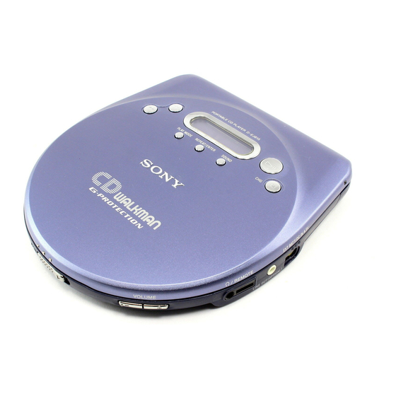
D-E880/EJ815
Photo: D-EJ815 Silver model
Model Name Using Similar Mechanism
CD Mechanism Type
Optical Pick-Up Name
SPECIFICATIONS
US Model
E Model
Chinese Model
Tourist Model
NEW
US
: CDM-3022EBG
Other : CDM-3022EBA
US
: DAX-22G
Other : DAX-22E
PORTABLE CD PLAYER
D-EJ815
D-E880
Advertisement
Table of Contents

Related Manuals for Sony D-E880


Summary of Contents for Sony D-E880
- Page 1 D-E880/EJ815 SERVICE MANUAL US Model E Model Ver 1.0 1999. 10 Chinese Model D-EJ815 Tourist Model D-E880 Photo: D-EJ815 Silver model Model Name Using Similar Mechanism : CDM-3022EBG CD Mechanism Type Other : CDM-3022EBA : DAX-22G Optical Pick-Up Name Other : DAX-22E...
-
Page 2: Table Of Contents
LINE WITH MARK 0 ON THE SCHEMATIC DIAGRAMS AND IN THE PARTS LIST ARE CRITICAL TO SAFE OPERATION. REPLACE THESE COMPONENTS WITH SONY PARTS WHOSE PART NUMBERS APPEAR AS SHOWN IN THIS MANUAL OR IN SUPPLEMENTS PUB- LISHED BY SONY. -
Page 3: Servicing Notes
SECTION 1 SERVICING NOTES Precautions for Checking Emission of Laser Diode NOTES ON HANDLING THE OPTICAL PICK-UP Laser light of the equipment is focused by the object lens in the BLOCK OR BASE UNIT optical pick-up so that the light focuses on the reflection surface of the disc. -
Page 4: General
SECTION 2 This section is extracted from instruction manual. GENERAL – 4 –... -
Page 5: Disassembly
SECTION 3 DISASSEMBLY Note: Follow the disassembly procedure in the numerical order given. CABINET (UPPER) SUB ASSY, CABINET (LOWER) SUB ASSY 1 open the upper lid sub assy. 2 three screws (B2) 5 cabinet (upper) sub assy 3 five claws 3 three claws 6 cabinet (lower) sub assy 4 flexible board... - Page 6 Note: Follow the disassembly procedure in the numerical order given. INSTALLATION UPPER LID SUB ASSY upper lid sub assy 1 flexible board 3 three bosses 2 cabinet (upper) sub assy 2 switching arm assy After sticking the switching arm assy into the hole on the cabinet, connect them with screw.
-
Page 7: Electrical Adjustments
SECTION 4 ELECTRICAL ADJUSTMENTS The CD section adjustments are done automatically in this set. Focus bias Check In case of operation check, confirm that focus bias. Condition: • Hold the set in horizontal state. Precautions for Check 1. Perform check in the order given. Connection: 2. -
Page 8: Diagrams
D-E880/EJ815 SECTION 5 DIAGRAMS 5-1. BLOCK DIAGRAM – MAIN Section (1/2) – RF AMP, DIGITAL SIGNAL PROCESSOR, DIGITAL SERVO PROCESSOR, D-RAM CONTROLLER IC601 DETECTOR WDCK DOUT DIGITAL DOUT WFCK (Page 11) D-RAM IC602 RFDC RFAC XTAO XTAI D0-D3 RFAC OPTICAL PICK-UP BLOCK... - Page 9 D-E880/EJ815 5-2. BLOCK DIAGRAM – MAIN Section (2/2) – B+ SWITCH VCC +3V Q601 DOUT (Page 10) J301 OPTICAL TRANSCEIVER LINE OUT (OPTICAL) (LINE OUT JACK) MUTING Q301 J302 HEADPHONE ON/OFF SWITCH / REMOTE HEADPHONE AMP IC302 IC351 IN_R OUT_R...
-
Page 10: Block Diagram - Power Supply Section
D-E880/EJ815 5-3. BLOCK DIAGRAM – POWER SUPPLY Section – • Waveforms 1 IC401 qd CLOCK, IC402 9 CLK IC601 wg CLOK, IC801 q; SCK 6 IC601 o; BCK (Page 9) 2 V/DIV, 2 µs/DIV 1 V/DIV, 200 ns/DIV (Page 9) 2.1 Vp-p... -
Page 11: Printed Wiring Board
D-E880/EJ815 5-4. PRINTED WIRING BOARD • Semiconductor Location Ref. No. Location D401 D-13 Note on Printed Wiring Board: D402 C-15 • X : parts extracted from the component side. D403 B-15 • Y : parts extracted from the conductor side. - Page 12 D-E880/EJ815 5-5. SCHEMATIC DIAGRAM • • See page 15 for Waveforms See page 23 for IC Block Diagrams. HEADPHONE ON/OFF SWITCH Note on Schematic Diagram: • All capacitors are in µF unless otherwise noted. pF: µµF 50 WV or less are not indicated except for electrolytics and tantalums.
- Page 13 • IC Block Diagrams IC401 MPC17A52ZFTA IC601 CXD3027R IC602 MSM51X17400D-10TFSR1 IC351 TA2120FN (EL) 120 119 118 117 116 115 114 113 112 111 110 109 108 107 106 105 104 103 102 101 100 99 98 97 96 95 94 93 92 91 BIAS BEEP 58 57 56...
-
Page 14: 5-6. Ic Pin Function Description
5-6. IC PIN FUNCTION DESCRIPTION • IC801 (SYSTEM CONTROLLER) TMP88CM22F-1A28 (EXCEPT US: TYPE A), TMP88CM22F-1A35 (EXCEPT US: TYPE B), TMP88CM22F-1A42 (US) Pin No. Pin Name Description — Ground terminal IRRMC Not used (Fixed at “L”) FOKI Focus OK signal input from the digital servo processor (IC601) “L”: NG, “H”: OK AGCCON AGC control pulse signal output terminal XLEDDISP... - Page 15 Pin No. Pin Name Description HOLD HOLD switch (S804) input terminal “L”: hold ON, “H”: hold OFF EX BATT External battery detection signal input terminal XSPDOE Control signal output to the spindle motor driver (IC402) XHGON Optical pick-up power ON/OFF control signal output terminal “L”: ON XLAT Serial data latch pulse signal output to the CXD3027R (IC601) XSOE...
-
Page 16: Exploded Views
SECTION 6 EXPLODED VIEWS NOTE: • -XX and -X mean standardized parts, so they • Items marked “*” are not stocked since they The components identified by mark 0 or dotted line with mark may have some difference from the original are seldom required for routine service. - Page 17 (2) MAIN BOARD SECTION Ref. No. Part No. Description Remark Ref. No. Part No. Description Remark 4-224-048-01 FOOT, RUBBER 4-224-020-01 KNOB (HOLD) (FOR BLUE) X-4952-204-1 CABINET (REAR) SUB ASSY (FOR BLUE) 4-224-020-11 KNOB (HOLD) (FOR SILVER) (E880) A-3323-346-A MAIN BOARD, COMPLETE (EXCEPT US) X-4952-327-1 CABINET (LOWER) SUB ASSY (FOR SILVER) A-3323-459-A MAIN BOARD, COMPLETE (US) (E880)
- Page 18 (3) OPTICAL PICK-UP SECTION (CDM-3022EBG (US)) (CDM-3022EBA (EXCEPT US)) M902 M901 not supplied The components identified by mark 0 or dotted line with mark 0 are critical for safety. Replace only with part number specified. Ref. No. Part No. Description Remark Ref.
-
Page 19: Electrical Parts List
SECTION 7 MAIN ELECTRICAL PARTS LIST NOTE: • Due to standardization, replacements in the • RESISTORS • CAPACITORS parts list may be different from the parts speci- All resistors are in ohms. uF: µF fied in the diagrams or the components used METAL: Metal-film resistor. - Page 20 MAIN Ref. No. Part No. Description Remark Ref. No. Part No. Description Remark C606 1-162-965-11 CERAMIC CHIP 0.0015uF 10% D601 8-719-988-78 DIODE SB007W03Q C607 1-164-156-11 CERAMIC CHIP 0.1uF C608 1-162-927-11 CERAMIC CHIP 100PF < FERRITE BEAD/RESISTOR > C609 1-125-891-11 CERAMIC CHIP 0.47uF C611 1-162-970-11 CERAMIC CHIP...
- Page 21 MAIN Ref. No. Part No. Description Remark Ref. No. Part No. Description Remark < TRANSISTOR > R405 1-218-887-11 METAL CHIP 0.5% 1/16W R406 1-218-889-11 METAL CHIP 0.5% 1/16W Q301 8-729-043-90 TRANSISTOR IMX9T110 R407 1-216-839-11 METAL CHIP 1/16W Q302 8-729-930-02 TRANSISTOR UMD2 Q401 8-729-023-89 FET...
- Page 22 MAIN Ref. No. Part No. Description Remark Ref. No. Part No. Description Remark R821 1-216-864-11 METAL CHIP 1/16W R476 1-216-851-11 METAL CHIP 330K 1/16W R822 1-216-864-11 METAL CHIP 1/16W R477 1-216-845-11 METAL CHIP 100K 1/16W R824 1-216-864-11 METAL CHIP 1/16W R480 1-216-841-11 METAL CHIP 1/16W...
- Page 23 D-E880/EJ815 Ref. No. Part No. Description Remark Ref. No. Part No. Description Remark 1-569-007-11 ADAPTOR, CONVERSION 2P (E880/EJ815: E33) 1-756-008-11 CASE,BATTERY (EJ815: US) 1-756-035-11 BATTERY PACK (NC-WMAA) (E880 /EJ815: E13, E33, HK, CH) 1-756-035-31 BATTERY PACK (NC-WMAA) (EJ815: US) 3-043-927-11 MANUAL, INSTRUCTION (ENGLISH)