Bosch MIC IP fusion 9000i Installation Manual
Hide thumbs
Also See for MIC IP fusion 9000i:
- Operation manual (80 pages) ,
- Installation manual (60 pages) ,
- User manual (93 pages)
Table of Contents
Advertisement
Quick Links
Advertisement
Table of Contents

Related Manuals for Bosch MIC IP fusion 9000i


Summary of Contents for Bosch MIC IP fusion 9000i
- Page 1 MIC IP fusion 9000 HD Installation Manual...
-
Page 3: Table Of Contents
Connect the Camera to the Network Typical System Configurations Troubleshooting Maintenance Decommissioning 13.1 Transfer 13.2 Disposal Technical data Best Practices for Outdoor Installation Status Codes Support services and Bosch Academy Bosch Security Systems 2021-05 | 1.3 | F.01U.334.820 Installation Manual... -
Page 4: Safety
Legal Information Copyright This manual is the intellectual property of Bosch Security Systems, and is protected by copyright. All rights reserved. Trademarks All hardware and software product names used in this document are likely to be registered trademarks and must be treated accordingly. -
Page 5: Safety Precautions
Notice! This symbol indicates information or a company policy that relates directly or indirectly to the safety of personnel or protection of property. Bosch Security Systems 2021-05 | 1.3 | F.01U.334.820 Installation Manual... -
Page 6: Important Safety Instructions
– Do not point the camera at the sun. Bosch Security Systems will not be liable for any damage to cameras that have been pointed directly at the sun. When transporting, take extra care to protect the wiper and the camera window(s). - Page 7 Notice! Bosch recommends the use of surge/lightning protection devices (sourced locally) to protect network and power cables and the camera installation site. Refer to NFPA 780, Class 1 & 2, UL96A, or the equivalent code appropriate for your country/region, and to local building codes.
-
Page 8: Important Notices
Camera signal - Protect the cable with a primary protector if the camera signal is beyond 140 feet, in accordance with NEC800 (CEC Section 60). Environmental statement - Bosch has a strong commitment towards the environment. This device has been designed to respect the environment as much as possible. - Page 9 This is a class A product. In a domestic environment this product may cause radio interference, in which case the user may be required to take adequate measures. Note: Changes or modifications not expressly approved by Bosch could void the user’s authority to operate the equipment.
- Page 10 UL MAKES NO REPRESENTATIONS, WARRANTIES, OR CERTIFICATIONS WHATSOEVER REGARDING THE PERFORMANCE OR RELIABILITY OF ANY SECURITY OR SIGNALING-RELATED FUNCTIONS OF THIS PRODUCT. Refer to – Best Practices for Outdoor Installation, page 43 2021-05 | 1.3 | F.01U.334.820 Bosch Security Systems Installation Manual...
-
Page 11: Customer Support And Service
MIC IP fusion 9000 HD Safety | en Customer Support and Service If this unit needs service, contact the nearest Bosch Security Systems Service Center for authorization to return and shipping instructions. USA and Canada Telephone: 800-289-0096, option 5 Fax: 800-366-1329 Email: repair@us.bosch.com... -
Page 12: Introduction
Sales or Customer Service Representative from Bosch Security Systems. – Do not use this product if any component appears to be damaged. Please contact Bosch Security Systems in the event of damaged goods. – The original packing carton (if undamaged) is the safest container in which to transport the unit and must be used if returning the unit for service. -
Page 13: Configuration With Project Assistant App
You can also use the Project Assistant app to complete the initial configuration of the camera. In order to use this device with the Project Assistant app by Bosch, you must download the app from the Bosch Download Store, from Google Play, or from the Apple Store. -
Page 14: Product Description
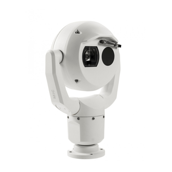
Make sure that the installation conditions comply with the specified stresses of vibration and shock as mentioned in the datasheet. The MIC IP fusion 9000i camera is a day/night, IP PTZ camera with dual optical/thermal imagers. Ruggedized and weatherproof, the camera offers a reliable, robust, and high-quality surveillance solution for extreme security applications. -
Page 15: Installation Overview
To maintain the Type 6P rating when the camera is mounted to a MIC-DCA, installers must make sure that the user-supplied cable glands or conduit connections have Type 6P ratings. Bosch Security Systems 2021-05 | 1.3 | F.01U.334.820 Installation Manual... - Page 16 Camera connections (including power/communication) Refer to Connection, page 32 . Optional accessories Refer to (Optional) Installing a Sunshield. Camera settings Refer to Configuration. Refer to – Best Practices for Outdoor Installation, page 43 2021-05 | 1.3 | F.01U.334.820 Bosch Security Systems Installation Manual...
-
Page 17: Mounting
(sold separately): – MIC-9K-IP67-5PK (IP67 Connector kit for MIC IP fusion 9000i, MIC IP ultra 7100i, and MIC IP starlight 7100i cameras) To have an installation rated IP67, you must use the appropriate IP67 Connector Kit from Bosch. - Page 18 If the camera is installed in a highly exposed location where lightning strikes may occur, then Bosch recommends installing a separate lightning conductor within 0.5 m (1.6 ft) of the camera and at least 1.5 m (4.9 ft) higher than the camera. A good earth bonding connection to the camera housing itself will provide protection against damage from secondary strikes.
-
Page 19: Mounting Options
The figures below illustrate the tilt range of the camera in upright orientation and in inverted orientation. 90° 90° 56° 56° 56° 56° 56° 56° Tilt range of MIC IP fusion 9000i camera Bosch Security Systems 2021-05 | 1.3 | F.01U.334.820 Installation Manual... -
Page 20: Mounting Bracket Options
Bosch sells a complete series of mounting brackets that support multiple mounting configurations. Always use only Bosch-supplied mounts, which are designed for safe installation of your MIC camera. Refer to the MIC Series Mounting Brackets Installation Guide for complete installation instructions. - Page 21 Note: The figure identifies the part numbers, as well as the codes for the available colors (-BD for black, -WD for white, and -MG for grey) of each mounting accessory. Bosch Security Systems 2021-05 | 1.3 | F.01U.334.820 Installation Manual...
- Page 22 Note: Always install an SCA when you install a wall mount for any installation configuration. Route cables through the bottom of the SCA (to prevent water from running into the side or top of the SCA along the cables). 2021-05 | 1.3 | F.01U.334.820 Bosch Security Systems Installation Manual...
-
Page 23: Considerations For Mounting The Camera In Inverted Orientation
Direct surface mount (inverted) with base gasket + IP67 Weatherization/Connector Kit Considerations for Mounting the Camera in Inverted Orientation To change the camera orientation to “Inverted,” complete the following steps: Remove the camera from the shipping box. Bosch Security Systems 2021-05 | 1.3 | F.01U.334.820 Installation Manual... - Page 24 Seal the mount so that moisture or water cannot collect and stay in the bottom of the MIC camera. The figure that follows shows the camera installed in inverted orientation on a pole. 2021-05 | 1.3 | F.01U.334.820 Bosch Security Systems Installation Manual...
- Page 25 MIC IP fusion 9000 HD Mounting | en Figure 5.5: MIC camera mounted in inverted orientation (on pole) Bosch Security Systems 2021-05 | 1.3 | F.01U.334.820 Installation Manual...
-
Page 26: (Optional) Configuration Programming In The Shipping Box
3. Configure the camera. Refer to the separate User Manual for details. 4. Disconnect the wires/cables from the connectors in the base of the camera. Refer to – (Optional) Configuration Programming on a Temporary Table-top Stand, page 27 2021-05 | 1.3 | F.01U.334.820 Bosch Security Systems Installation Manual... -
Page 27: Optional) Configuration Programming On A Temporary Table-Top Stand
(180°). Note that the visor will now be near the body of the camera. Disconnect the wires/cables from the connectors in the base of the camera. Bosch Security Systems 2021-05 | 1.3 | F.01U.334.820 Installation Manual... -
Page 28: Installing A Mic Camera On A Hinged Dca
Blanking plug, M25 x 1.5, with O-ring Quick Installation Guide Additional Tools Required Warning! Ensure not to damage the paint on the housing of the camera or the mount. 2021-05 | 1.3 | F.01U.334.820 Bosch Security Systems Installation Manual... - Page 29 Installing a MIC Camera on a Hinged DCA | en 3/4” NPT 1. Attach the DCA to the mounting location using user-supplied hardware (item 1). (Bosch recommends stainless steel bolts and washers.) 2. Attach user-supplied conduit or glands to the side hole or to the bottom hole. If applicable, use the conduit adapter (male M25 to female ¾...
- Page 30 DCA hook (item 1). Avoid pinching the wires! (item 2). Loosen the hook bolts, and then slide the hook down to secure the camera pin. Fully tighten the hook bolts (item 3). 2021-05 | 1.3 | F.01U.334.820 Bosch Security Systems Installation Manual...
- Page 31 (item 4 in step 1) to the same connection point. 12. Carefully tip the camera to its final position. Avoid pinching wires between the camera base and the DCA! Insert four washers and hex bolts (supplied). Bosch Security Systems 2021-05 | 1.3 | F.01U.334.820 Installation Manual...
-
Page 32: Connection
(UPS) supply is necessary. The UPS must have a Transfer Time between 2–6 ms and a Backup Runtime of greater than 5 seconds for the power level as specified on the product datasheet. Maximum wire distances from 24 VAC power supply to MIC IP fusion 9000i camera VA / Watts 14 AWG... -
Page 33: Ethernet Connections
Terminal Connector RJ45, Male High PoE (95 W) Use a midspan sold by Bosch, or a midspan that is offered as a compatible alternative. Note: Consult the National Electrical Code (NEC) or other regional standards for cable bundling requirements and limitations. -
Page 34: Camera Connections
Note: If the MIC camera will be installed directly to a mounting surface, instead of onto a MIC DCA or a MIC wall mount bracket, Bosch recommends using the connector kit for your model of camera to protect the connections against moisture and dust particles. Each kit provides components for connecting as many as 5 MIC cameras. -
Page 35: Connect The Camera To The Network
4. Attach the ground wire from the camera to an earth-ground connection on the mounting surface using the supplied screw or a suitable user-supplied fastener. 5. If applicable, connect the AUDIO IN and AUDIO OUT wires to the appropriate line level audio device. Bosch Security Systems 2021-05 | 1.3 | F.01U.334.820 Installation Manual... -
Page 36: Typical System Configurations
| Typical System Configurations MIC IP fusion 9000 HD Typical System Configurations MIC IP fusion 9000i System Configuration Options 2021-05 | 1.3 | F.01U.334.820 Bosch Security Systems Installation Manual... -
Page 37: Troubleshooting
- If providing power via High PoE, ensure that the lights on the midspan indicate correct operation. If they do not, see the midspan manual for further details. - Check to see if you can access a web page. Bosch Security Systems 2021-05 | 1.3 | F.01U.334.820 Installation Manual... - Page 38 Camera reboots frequently or Your camera has an improper network connection. intermittently Test your camera with another power supply. Check the Bosch website for a software update that might address the issue. No OSD messages appear. Bosch’s Video SDK is required. Video management software from third parties does not use the SDK.
- Page 39 Explanation Solution The picture shows Check to see if there the heat images that aren’t of objects are being reflected present in the scene. off a surface causing thermal reflections. Bosch Security Systems 2021-05 | 1.3 | F.01U.334.820 Installation Manual...
-
Page 40: Maintenance
No User-serviceable Parts Except for the external wiper blade, the device contains no user-serviceable parts. Contact your local Bosch service center for device maintenance and repair. In the event of failure, the device should be removed from site for repair. -
Page 41: Decommissioning
The unit should only be passed on together with this installation guide. 13.2 Disposal Disposal - Your Bosch product was developed and manufactured with high-quality material and components that can be recycled and reused. This symbol means that electronic and electrical appliances, which have reached the end of their working life, must be collected and disposed of separately from household waste material. -
Page 42: Technical Data
| Technical data MIC IP fusion 9000 HD Technical data For product specifications, see the datasheet for your camera, available on the appropriate product pages of the Online Product Catalog at www.boschsecurity.com. 2021-05 | 1.3 | F.01U.334.820 Bosch Security Systems Installation Manual... -
Page 43: Best Practices For Outdoor Installation
AUTODOME and MIC cameras. The illustration can represent any IP camera. Mounting hardware varies between units. Figure 15.1: Correct outdoor installation with proper surge/lightning protection Bosch Security Systems 2021-05 | 1.3 | F.01U.334.820 Installation Manual... - Page 44 13 Down Conductor; refer to NFPA 780, 14 Install outdoor High PoE-compatible Class 1 and 2. surge protection as close as possible to the camera. Connect to the Equipment Grounding Electrode. 15 Lightning Rod Grounding Electrode 2021-05 | 1.3 | F.01U.334.820 Bosch Security Systems Installation Manual...
-
Page 45: Status Codes
IEEE 802.3af) with insufficient power the camera's window defroster. output may be connected to the camera.* Note: MIC IP fusion 9000i only. Capacity of external PoE device is An incorrect type of PoE+ or PoE++ (such as insufficient to support operation of one based on IEEE 802.3af or IEEE 802.3at) - Page 46 2. Verify the integrity/tightness of the external fasteners. Tighten where necessary. 3. If obvious damage is present, stop using the camera and contact the nearest Bosch Security Systems Service Center. 4. If no damage is evident, power the camera off and then on, and then evaluate operational performance.
- Page 47 Configure the washer pre-position. If without washer pre-position being necessary, refer to the subchapter “Using the stored. Wiper/Washer (Bosch AUX/Pre-position Commands)” in the User Manual for details on configuring washer functions. Attempt was made to move to a pre- 1. Select/configure a different pre-position position that is mapped to an number for the desired location.
- Page 48 (and the window defrosters, for MIC IP fusion 9000i). If the log notes heater or defroster failure, contact the nearest Bosch Security Systems Service Center. 3. If operation is obstructed because of...
- Page 49 If these actions do not resolve this problem, contact the nearest Bosch Security Systems Service Center. * Note: The MIC IP fusion 9000i camera requires a Bosch 95 W midspan (NPD-9501A) or a customer-tested/verified alternative. Caution! If you choose not to use a switch or midspan with the appropriate Power Sourcing Equipment (PSE) chip, then the camera will not recognize the PoE as compliant, and the camera firmware may disable some or all functionality.
-
Page 50: Support Services And Bosch Academy
Troubleshooting – Repair & Exchange – Product Security Bosch Building Technologies Academy Visit the Bosch Building Technologies Academy website and have access to training courses, video tutorials and documents: www.boschsecurity.com/xc/en/support/training/ 2021-05 | 1.3 | F.01U.334.820 Bosch Security Systems Installation Manual... - Page 51 MIC IP fusion 9000 HD Support services and Bosch Academy | Bosch Security Systems 2021-05 | 1.3 | F.01U.334.820 Installation Manual...
- Page 52 | Support services and Bosch Academy MIC IP fusion 9000 HD 2021-05 | 1.3 | F.01U.334.820 Bosch Security Systems Installation Manual...
- Page 54 Bosch Security Systems B.V. Torenallee 49 5617 BA Eindhoven Netherlands www.boschsecurity.com © Bosch Security Systems B.V., 2021 202105111626...