Table of Contents
Advertisement
Quick Links
This service information is designed for experienced repair technicians only and is not designed for use by the general public.
It does not contain warnings or cautions to advise non-technical individuals of potential dangers in attempting to service a product.
Products powered by electricity should be serviced or repaired only by experienced professional technicians. Any attempt to service
or repair the products dealt with in this service information by anyone else could result in serious injury or death.
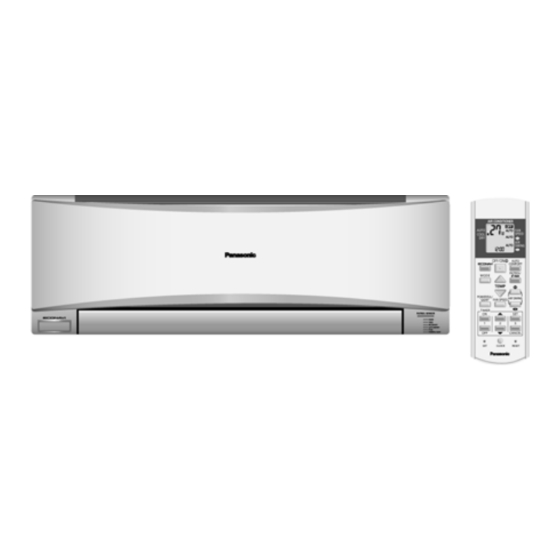
Indoor Unit
CS-C12MKF
CS-C18MKF
CS-C24MKF
CS-C28MKF
WARNING
© Panasonic HA Air-Conditioning (M) Sdn. Bhd. 2011.
Unauthorized copying and distribution is a violation of law.
Order No: PHAAM1101038C3
Outdoor Unit
CU-C12MKF
CU-C18MKF
CU-C24MKF
CU-C28MKF
Advertisement
Table of Contents

Related Manuals for Panasonic CS-C12MKF


Summary of Contents for Panasonic CS-C12MKF
- Page 1 Products powered by electricity should be serviced or repaired only by experienced professional technicians. Any attempt to service or repair the products dealt with in this service information by anyone else could result in serious injury or death. © Panasonic HA Air-Conditioning (M) Sdn. Bhd. 2011. Unauthorized copying and distribution is a violation of law.
-
Page 2: Table Of Contents
Operation Characteristics......92 9. Electronic Circuit Diagram ......23 19. Service Data ........... 100 CS-C12MKF CU-C12MKF ......23 CS-C18MKF CU-C18MKF ......24 19.1 CS-C12MKF CU-C12MKF ...... 100 CS-C24MKF CU-C24MKF ......25 19.2 CS-C18MKF CU-C18MKF ...... 101 CS-C28MKF CU-C28MKF ......26 19.3 CS-C24MKF CU-C24MKF ...... 102 19.4... -
Page 3: Safety Precautions
1. Safety Precautions • Read the following “SAFETY PRECAUTIONS” carefully before perform any servicing. • Electrical work must be installed or serviced by a licensed electrician. Be sure to use the correct rating of the power plug and main circuit for the model installed. •... - Page 4 WARNING 20. After completion of installation or service, confirm there is no leakage or refrigerant gas. It may generate toxic gas when the refrigerant contacts with fire. 21. Ventilate if there is refrigerant gas leakage during operation. It may cause toxic gas when refrigerant contacts with fire. 22.
-
Page 5: Specification
2. Specification Indoor CS-C12MKF CS-C18MKF Model Outdoor CU-C12MKF CU-C18MKF Performance Test Condition AHAM AHAM Phase, Hz Single, 50 Single, 50 Power Supply 3.58 3.60 5.28 5.28 Capacity BTU/h 12200 12300 18000 18000 kJ/h 12890 12960 19010 19010 Running Current Input Power 1.13k... - Page 6 Height(I/D / O/D) mm (inch) 290 (11-7/16) 540 (21-9/32) 290 (11-7/16) 540 (21-9/32) Dimension Width (I/D / O/D) mm (inch) 870 (34-9/32) 780 (30-23/32) 1070 (42-5/32) 780 (30-23/32) Depth (I/D / O/D) mm (inch) 204 (8-1/16) 289 (11-13/32) 235 (9-9/32) 289 (11-13/32) Weight Net (I/D / O/D)
- Page 7 Indoor CS-C24MKF CS-C28MKF Model Outdoor CU-C24MKF CU-C28MKF Performance Test Condition AHAM AHAM Phase, Hz Single, 50 Single, 50 Power Supply 7.03 7.03 8.20 8.20 Capacity BTU/h 24000 24000 28000 28000 kJ/h 25310 25310 29520 29520 Running Current 11.2 11.3 13.1 13.8 Input Power 2.35k...
- Page 8 Height(I/D / O/D) mm (inch) 290 (11-7/16) 695 (27-3/8) 290 (11-7/16) 750 (29-17/32) Dimension Width (I/D / O/D) mm (inch) 1070 (42-5/32) 875 (34-15/32) 1070 (42-5/32) 875 (34-15/32) Depth (I/D / O/D) mm (inch) 235 (9-9/32) 320 (12-5/8) 235 (9-9/32) 345 (13-19/32) Weight Net (I/D / O/D)
-
Page 9: Features
Features • E-ion Air Purifying System with Patrol Sensor Active e-ions are released to catch dust particles and bring them back the large positively charged filter. Patrol Sensor color changes to indicate the dirt level in the air • Long Installation Piping CS/CU-C12MK, long piping up to 15 meters. -
Page 10: Location Of Controls And Components
4. Location of Controls and Components Indoor Unit Outdoor Unit Remote Control... -
Page 11: Dimensions
5. Dimensions Indoor Unit 5.1.1 CS-C12MKF... - Page 12 5.1.2 CS-C18MKF CS-C24MKF CS-C28MKF...
-
Page 13: Outdoor Unit
Outdoor Unit 5.2.1 CU-C12MKF CU-C18MKF 5.2.2 CU-C24MKF... - Page 14 5.2.3 CU-C28MKF...
-
Page 15: Refrigeration Cycle Diagram
6. Refrigeration Cycle Diagram... -
Page 16: Block Diagram
7. Block Diagram 7.1.1 CS-C12MKF CU-C12MKF... - Page 17 7.1.2 CS-C18MKF CU-C18MKF CS-C24MKF CU-C24MKF...
- Page 18 7.1.3 CS-C28MKF CU-C28MKF...
-
Page 19: Wiring Connection Diagram
8. Wiring Connection Diagram CS-C12MKF CU-C12MKF Resistance of Indoor Fan Motor Windings Resistance of Compressor Windings MODEL CS-C12MKF MODEL CU-C12MKF CONNECTION CWA921434 CONNECTION 2KS210D5AA06 BLUE-YELLOW 351.3Ω 2.279Ω YELLOW-RED 343.9Ω 3.526Ω Note: Resistance at 25°C of ambient temperature. Note: Resistance at 20°C of ambient temperature. -
Page 20: Cs-C18Mkf Cu-C18Mkf
CS-C18MKF CU-C18MKF Resistance of Outdoor Fan Motor Windings Resistance of Compressor Windings MODEL CU-C18MKF MODEL CU-C18MKF CONNECTION CWA951676 CONNECTION 2KS324D5BB06 BLUE-YELLOW 198Ω 1.453Ω YELLOW-RED 293Ω 3.151Ω Note: Resistance at 20°C of ambient temperature. Note: Resistance at 20°C of ambient temperature. -
Page 21: Cs-C24Mkf Cu-C24Mkf
CS-C24MKF CU-C24MKF Resistance of Outdoor Fan Motor Windings Resistance of Compressor Windings MODEL CU-C24MKF MODEL CU-C24MKF CONNECTION CWA951689 CONNECTION 2JS438D3CB04 BLUE-YELLOW 64Ω 1.121Ω YELLOW-ORANGE 90Ω 2.535Ω YELLOW-RED 55Ω Note: Resistance at 20°C of ambient temperature. Note: Resistance at 20°C of ambient temperature. -
Page 22: Cs-C28Mkf Cu-C28Mkf
CS-C28MKF CU-C28MKF Resistance of Outdoor Fan Motor Windings Resistance of Compressor Windings MODEL CU-C28MKF MODEL CU-C28MKF CONNECTION CWA951689 CONNECTION 2JD514D3AA03 BLUE-YELLOW 64Ω 0.708Ω YELLOW-ORANGE 90Ω 1.985Ω YELLOW-RED 55Ω Note: Resistance at 20°C of ambient temperature. Note: Resistance at 20°C of ambient temperature. -
Page 23: Electronic Circuit Diagram
9. Electronic Circuit Diagram CS-C12MKF CU-C12MKF... -
Page 24: Cs-C18Mkf Cu-C18Mkf
CS-C18MKF CU-C18MKF... -
Page 25: Cs-C24Mkf Cu-C24Mkf
CS-C24MKF CU-C24MKF... -
Page 26: Cs-C28Mkf Cu-C28Mkf
CS-C28MKF CU-C28MKF... -
Page 27: Printed Circuit Board
10. Printed Circuit Board 10.1 Indoor Unit 10.1.1 Main Printed Circuit Board 10.1.1.1 CS-C12MKF... - Page 28 10.1.1.2 CS-C18MKF CS-C24MKF CS-C28MKF...
- Page 29 10.1.2 Indicator Printed Circuit Board 10.1.3 Receiver Printed Circuit Board 10.1.4 High Voltage Power Supply Printed Circuit Board 10.1.5 Comparator Printed Circuit Board...
- Page 30 10.1.6 Human Activity Sensor Printed Circuit Board...
-
Page 31: Installation Instruction
11.1.3 Indoor/Outdoor Unit Installation 11. Installation Instruction Diagram 11.1 Select the Best Location 11.1.1 Indoor Unit • Do not install the unit in excessive oil fume area such as kitchen, workshop and etc. • There should not be any heat source or steam near the unit. -
Page 32: Indoor Unit
11.2 Indoor Unit 11.2.1 How to Fix Installation Plate The mounting wall shall be strong and solid enough to prevent if from the vibration. The centre of installation plate should be at more than at right and left of the wall. The distance from installation plate edge to ceiling should more than From installation plate left edge to unit’s left side is From installation plate right edge to unit’s right side is... - Page 33 11.2.3 Indoor Unit Installation 11.2.3.1 For the right rear piping 11.2.3.2 For the right and right bottom piping 11.2.3.3 For the embedded piping (This can be used for left rear piping and bottom piping also.)
- Page 34 11.2.4 Connect the Cable to the Indoor Unit The power supply cord, indoor and outdoor unit connection cable can be connected without removing the front grille. Install the indoor unit on the installation holder that mounted on the wall. Open the front panel and grille door by loosening the screw. Cable connection to the power supply through Isolating Devices (Disconnecting means).
- Page 35 Remove the tapes and connect the power supply cord and connecting cable between indoor unit and outdoor unit according to the diagram below. Secure the power supply cord and connection cable onto the control board with the holder. Close grille door by tighten with screw and close the front panel. Note: •...
-
Page 36: Outdoor Unit
11.3 Outdoor Unit 11.3.1 Install the Outdoor Unit • After selecting the best location, start installation according to Indoor/Outdoor Unit Installation Diagram. Fix the unit on concrete or rigid frame firmly and horizontally by bolt nut (ø10mm). When installing at roof, please consider strong wind and earthquake. Please fasten the installation stand firmly with bolt or nails. - Page 37 FOR ENVIRONMENT PROTECTION, MANUFACTURER STRONGLY RECOMMENDS TO USE EVACUATION METHOD. 11.3.3 Evacuation of the Equipment Connect a charging hose with a push pin to the Low side of a charging set and the service port of the 3-way valve. Be sure to connect the end of the charging hose with the push pin to the service port. Connect the center hose of the charging set to a vacuum pump.
- Page 38 11.3.4 Air Purging of the Piping and Indoor The remaining air in the Refrigerant cycle which contains moisture may cause malfunction on the compressor. Remove the caps from the 2-way and 3-way valves. Remove the service-port cap from the 3-way valves. To open the valve, turn the valve stem of 2-way valve counter-clockwise approx.
- Page 39 11.3.6 Pipe Insulation Please carry out insulation at pipe connection portion as mentioned in Indoor/Outdoor Unit Installation Diagram. Please wrap the insulated piping end to prevent water from going inside the piping. If drain hose or connecting piping is in the room (where dew may form), please increase the insulation by using POLY-E-FOAM with thickness 6mm or above.
-
Page 40: Installation Instruction
12. Installation Instruction 12.1 Select the Best Location 12.1.3 Indoor/Outdoor Unit Installation Diagram (For C28MKF only) 12.1.1 Indoor Unit • Do not install the unit in excessive oil fume area such as kitchen, workshop and etc. • There should not be any heat source or steam near the unit. -
Page 41: Indoor Unit
12.2 Indoor Unit 12.2.1 How to Fix Installation Plate The mounting wall is strong and solid enough to prevent if from the vibration. The centre of installation plate should be at more than at right and left of the wall. The distance from installation plate edge to ceiling should more than From installation plate left edge to unit’s left side is From installation plate right edge to unit’s right side is... - Page 42 12.2.3 Indoor Unit Installation 12.2.3.1 For the right rear piping Step-1 Pull out the Indoor piping Step-2 Install the Indoor Unit Step-3 Secure the Indoor Unit Step-4 Insert the connecting cable 12.2.3.2 For the right and right bottom piping Step-1 Pull out the Indoor piping Step-2 Install the Indoor Unit...
- Page 43 12.2.4 Connect the Cable to the Indoor Unit The inside and outside connecting cable can be connected without removing the front grille. Connecting cable between indoor unit and outdoor unit shall be approved polychloroprene sheathed 4 x 1.5 mm flexible cord, type designation 245 IEC 57 or heavier cord.
- Page 44 12.2.5 Wire Stripping And Connecting Requirement 12.2.5.1 Cutting and flaring the piping Please cut using pipe cutter and then remove the burrs. Remove the burrs by using reamer. If burrs are not removed, gas leakage may be caused. Turn the piping end down to avoid the metal powder entering the pipe.
-
Page 45: Outdoor Unit
12.3 Outdoor Unit 12.3.1 Install the Outdoor Unit • After selecting the best location, start installation according to Indoor/Outdoor Unit Installation Diagram. Fix the unit on concrete or rigid frame firmly and horizontally by bolt nut (ø10mm). When installing at roof, please consider strong wind and earthquake. Please fasten the installation stand firmly with bolt or nails. - Page 46 FOR ENVIRONMENT PROTECTION, MANUFACTURER STRONGLY RECOMMENDS TO USE EVACUATION METHOD. 12.3.3 Evacuation of the Equipment Connect a charging hose with a push pin to the Low side of a charging set and the service port of the 3-way valve. Be sure to connect the end of the charging hose with the push pin to the service port. Connect the center hose of the charging set to a vacuum pump.
- Page 47 12.3.4 Air Purging of the Piping and Indoor The remaining air in the Refrigerant cycle which contains moisture may cause malfunction on the compressor. Remove the caps from the 2-way and 3-way valves. Remove the service-port cap from the 3-way valves. To open the valve, turn the valve stem of 2-way valve counter-clockwise approx.
- Page 48 12.3.5 Connect the cable to the Outdoor Unit Remove the control board cover from the unit by loosening the screw. Cable connection to the power supply through Isolating Devices (Disconnecting means). Connect the approved polychloroprene sheathed power supply cord 3 x 4.0 mm , type designation 245 IEC 57 or heavier cord to the terminal board, and connect the others end of the cord to Isolating Devices (Disconnecting means).
-
Page 49: Operation Control
13. Operation Control 13.1 Cooling Operation • Cooling operation can be set using remote control. • This operation is applied to cool down the room temperature to the setting temperature set on the remote control. • The remote control setting temperature, which takes the reading of intake air temperature sensor, can be adjusted from 16°C to 30°C. - Page 50 13.1.2 Cooling Operation Time Diagram (For CS-C18MK CU-C18MK, CS-C24MK CU-C24MK and CS-C28MK CU-C28MK)
-
Page 51: Soft Dry Operation
13.2 Soft Dry Operation • Soft Dry operation can be set using remote control. • Soft Dry operation is applied to dehumidify and to perform a gentle cooling to the room. • This operation starts when the intake air temperature sensor reaches the setting temperature on the remote control. - Page 52 13.2.2 Soft Dry Operation Time Diagram (For CS-C18MK CU-C18MK, CS-C24MK CU-C24MK and CS-C28MK CU-C28MK)
-
Page 53: Automatic Operation
13.3 Automatic Operation • Automatic operation can be set using remote control. • This operation starts to operate with indoor fan at SLo speed for 20 seconds to judge the intake air temperature. • After judged the temperature, the operation mode is determined by referring to the below standard. ↑... -
Page 54: Indoor Fan Speed Control
13.4 Indoor Fan Speed Control • Indoor fan speed can be set using remote control. 13.4.1 Fan Speed Rotation Chart Fan Speed (rpm) Speed CS-C12MKF CS-C18MKF CS-C24MKF CS-C28MKF 1150 1430 1500 1530 1110 1280 1390 1490 1180 1240 1400 1140... - Page 55 For CS-C18MK, CS-C24MK and CS-C28MK Stop Manual Normal Auto Hi-90 Manual Me-90 Quiet CLo-90 Auto Hi-90 Me-90 Manual Powerful Auto Manual Normal Auto Manual Quiet Auto • Auto Fan Speed during cooling operation: Indoor fan will rotate alternately between off and on as shown in below diagram. At the beginning of each compressor starts operation, indoor fan speed increases gradually for deodorizing purpose.
-
Page 56: Outdoor Fan Speed Control
• Auto Fan Speed during Soft Dry operation. Indoor fan will rotate alternately between off and Lo-. At the beginning of each compressor starts operation, indoor fan will increase fan speed gradually for deodorizing purpose. When compressor turned off for 6 minutes, indoor fan will start at Lo- to circulate the air in the room. This is to obtain the actual reading of intake air temperature. - Page 57 For CS-C18MK, CS-C24MK and CS-C28MK Horizontal Closing Upper limit for cooling mode position 22° and soft dry mode/17° / 148° Swing up and down Lower limit for cooling mode and soft dry mode/39° 13.6.2 Manual Control • When the vertical airflow direction is set to Manual using the remote control, the automatic airflow is released and the airflow direction louver move up and down in the range shown in the diagram.
-
Page 58: Horizontal Airflow Direction Control
13.7 Horizontal Airflow Direction Control 13.7.1 Auto Control • When the horizontal airflow is set to Auto using the remote control, the vanes swings left and right as shown in the diagram. • When stopped with remote control, the discharge vanes are reset and stop at the reset position. •... -
Page 59: Quiet Operation
13.9 Quiet Operation (For Cooling Operation or cooling region of Soft Dry Operation) • To provide quiet cooling operation condition. • Once the Quiet Operation is set at the remote control, the Quiet LED brightness will be dimmed. The sound level will reduce around 2dB(A) for Lo fan speed or 3dB(A) for Hi/Me fan speed against the present operation sound level. -
Page 60: Timer Control
13.10 Timer Control 13.10.1 ON Timer • When the ON Timer is set by using the remote control, the unit will start to operate slightly before the set time, so that the room will reach nearly to the set temperature by the set time. •... -
Page 61: Patrol Operation
13.13 Patrol Operation • To monitor air dirtiness level by using Patrol sensor and to maintain air freshness by activates e-ion operation • Patrol operation starts condition When the unit operation is started with “OFF/ON” button When the unit stops, “Patrol” operation is selected, Patrol individual operation will start. During cooling only operation, “Patrol”... - Page 62 • Patrol Sensor Control First 2 minutes from Patrol function activates is stabilization time, during stabilization time, no air dirtiness level is monitored. The Air Dirtiness level is set to Clean, Patrol LED turns blue color. After that, Patrol sensor starts to record the resistance value at fixed interval. Higher resistance value indicates cleaner air.
- Page 63 • Airflow direction (Horizontal, Vertical) Control During any operation mode combines with Patrol operation, airflow direction follows respective operation mode. During Patrol individual operation if e-ion starts, only Auto Air Swing is allowed. Even if “Air Swing” button is pressed, no signal is sent to air conditioner, and no change on LCD display. During Patrol individual operation if e-ion stops, Airflow direction louver closed.
- Page 64 • Patrol Operation Demo Mode Patrol Operation Demo Mode start condition Press “Set” button continuously for 15 seconds by using pointer during Air Conditioner is OFF condition to enter internal setting mode. Press “Timer Decrement" button to select “Pt demo”. Press “Timer Set”...
-
Page 65: E-Ion Operation
13.14 E-ion operation • This operation provides clean air by producing negative ions to attract dust captured at the positively charged active e-ion filters. • e-ion operation start condition During unit running at any operation mode, if “e-ion” operation is selected, combination operation (operation mode + e-ion operation) starts. - Page 66 • e-ion Check Mode e-ion abnormality check mode Purpose is to improve sensor serviceability when sensor is malfunction. (1) Control starting condition When all of the conditions are formed Not in Patrol Demo mode. e-ion operation ON. When e-ion check mode signal is received; the procedure of selection is as shown: •...
- Page 67 • Error Detection Control When e-ion indicator blink, it indicates error listed below: Active e-ion Air Purifying system PCB main connector open: Judgment Method • During e-ion operation (include during Patrol operation), Active e-ion Air Purifying system main connector to PCB is opened. Troubleshooting Methods •...
-
Page 68: Auto Comfort And Eco Navi Operation
13.15 AUTO COMFORT and ECO NAVI Operation • Area of human availability, activity level and absent is judged based on pulses by using 2 infrared sensors. The internal setting temperature shift, fan speed and horizontal airflow direction are adjusted in order to provide comfort environment while maintain the energy saving level. - Page 69 13.15.1 Signal Detection 120º • Human Activity sensor will turns on according to infrared sensors signal detection. Signal detection Human Activity Indicator Possible detected human position area Sensor 1 Sensor 2 Left Center Right ■ ■ □ □ ■ ■ ■...
- Page 70 13.15.7 Setting Position Judgment • According to installation position when there is only one activity area detected, the horizontal airflow direction louver position is fixed according to chart below: Horizontal airflow direction louver position Target area Left installation Center installation Right installation •...
- Page 71 13.15.9 ECO NAVI and AUTO COMF Demo Mode • To enable ECO DEMO mode: Remote control normal mode Press continously for 15s Transmit Patrol default OFF/ON code (Buzzer: OFF:peep, ON:peep) Transmit Patrol demo code (Buzzer: OFF:peep, ON:peep) Transmit ECO demo code (Buzzer: OFF:peep, ON:peep) Transmit check code (Buzzer:peep)
- Page 72 13.15.10 Infrared Sensor Abnormality • Abnormality detection: Connector disconnection / Wire cut abnormality o Sensor judge Hi level continuously for 25 seconds Circuit abnormality o 70 seconds after power ON, if infrared sensor judge Lo level continuously for 25 seconds •...
-
Page 73: Protection Control
14. Protection Control 14.1 Restart Control (Time Delay Safety Control) • When the thermo-off temperature (temperature which compressor stops to operate) is reach during:- Cooling operation – the compressor stops for 3 minutes (minimum) before resume operation. Soft Dry operation – the compressor stops for 6 minutes (minimum) before resume operation. •... -
Page 74: Freeze Prevention Control
14.5 Freeze Prevention Control • To protect indoor heat exchanger from freezing and to prevent higher volume of refrigerant in liquid form return to compressor. • This control will activate when temperature of indoor heat exchanger falls below 2°C continuously for more than 4 minutes and compressor turn off. -
Page 75: Dew Prevention Control
14.7 Dew Prevention Control • To prevent dew formation at indoor unit discharge area. • This control starts if: Cooling mode or Quiet mode is activated. Remote Control setting temperature is less than 25°C. Fan speed is at CLo or QLo. Room temperature is constant (±1°C) for 30 minutes. -
Page 76: Servicing Mode
15. Servicing Mode 15.1 Auto OFF/ON Button Auto OFF/ON Auto OFF/ON Auto OFF/ON Button Pressed Button Pressed Button Pressed 5 sec 5 sec Auto Operation Test Run Operation Stop Various Setting Mode Stop (Forced Cooling Operation) “Beep” 2 x “Beep” AUTO OPERATION MODE The Auto Operation will be activated immediately once the Auto OFF/ON button is pressed. -
Page 77: Remote Control Button
15.2 Remote Control Button 15.2.1 SET Button • To check current remote control transmission code and store the transmission code to EEPROM: Press “Set” button continuously for 10 seconds by using pointer Press “Timer Set” button until a “beep” sound is heard as confirmation of transmission code change. •... -
Page 78: Troubleshooting Guide
16. Troubleshooting Guide 16.1 Refrigeration cycle system In order to diagnose malfunctions, ensure the air conditioner is free Normal Pressure and Outlet Air Temperature (Standard) from electrical problems before inspecting the refrigeration cycle. Gas Pressure Outlet air Temperature Such problems include insufficient insulation, problem with the (kg/cm (°C) power source, malfunction of a compressor and a fan. - Page 79 16.1.1 Relationship between the condition of the air conditioner and pressure and electric current Cooling Mode Condition of the air conditioner Low Pressure High Pressure Electric current during operation Insufficient refrigerant (gas leakage) Clogged capillary tube or strainer Short circuit in the indoor unit Heat radiation deficiency of the outdoor unit Inefficient compression...
-
Page 80: Disassembly And Assembly Instructions
High Voltage is generated in the electrical parts area by the capacitor. Ensure that the capacitor has discharged sufficiently before proceeding with repair work. Failure to heed this caution may result in electric shocks. 17.1 CS-C12MKF 17.1.1 Indoor Electronic Controllers, Cross Flow Fan and Indoor Fan Motor Removal Procedures 17.1.1.1... - Page 81 Figure 3 Figure 4 17.1.1.3 To remove discharge grille Figure 5...
- Page 82 17.1.1.4 To remove control board Figure 6 17.1.1.5 To remove cross flow fan and indoor fan motor Figure 7 Figure 8...
- Page 83 Figure 9 Figure 10...
-
Page 84: Cs-C18Mkf Cs-C24Mkf
WARNING High Voltage is generated in the electrical parts area by the capacitor. Ensure that the capacitor has discharged sufficiently before proceeding with repair work. Failure to heed this caution may result in electric shocks. 17.2 CS-C18MKF CS-C24MKF 17.2.1 Indoor Electronic Controllers, Cross Flow Fan and Indoor Fan Motor Removal Procedures 17.2.1.1 To remove front grille... - Page 85 17.2.1.3 To remove power electronic controller Figure 13 Figure 14 Figure 15...
- Page 86 17.2.1.4 To remove discharge grille Figure 16 17.2.1.5 To remove control board Figure 17 17.2.1.6 To remove cross flow fan and indoor fan motor Figure 18...
- Page 87 Figure 19 Figure 20 Figure 21...
-
Page 88: Cs-C28Mkf
WARNING High Voltage is generated in the electrical parts area by the capacitor. Ensure that the capacitor has discharged sufficiently before proceeding with repair work. Failure to heed this caution may result in electric shocks. 17.3 CS-C28MKF 17.3.1 Indoor Electronic Controllers, Cross Flow Fan and Indoor Fan Motor Removal Procedures 17.3.1.1 To remove front grille... - Page 89 17.3.1.3 To remove power electronic controller Figure 24 Figure 25 Figure 26...
- Page 90 17.3.1.4 To remove discharge grille Figure 27 17.3.1.5 To remove control board Figure 28 17.3.1.6 To remove cross flow fan and indoor fan motor Figure 29...
- Page 91 Figure 30 Figure 31 Figure 32...
-
Page 92: Technical Data
18. Technical Data 18.1 Operation Characteristics 18.1.1 CS-C12MKF CU-C12MKF • Cooling Characteristic Room temperature: 27°C (DBT), 19°C (WBT) Operation condition: High fan speed Piping length: 7.5m... - Page 93 • Piping Length Characteristic Outdoor temperature: 35°C (DBT), 24°C (WBT) Operation condition: High fan speed Piping length: 7.5m...
- Page 94 18.1.2 CS-C18MKF CU-C18MKF • Cooling Characteristic Room temperature: 27°C (DBT), 19°C (WBT) Operation condition: High fan speed Piping length: 5.0m...
- Page 95 • Piping Length Characteristic Outdoor temperature: 35°C (DBT), 24°C (WBT) Operation condition: High fan speed Piping length: 5.0m...
- Page 96 18.1.3 CS-C24MKF CU-C24MKF • Cooling Characteristic Room temperature: 27°C (DBT), 19°C (WBT) Operation condition: High fan speed Piping length: 5.0m...
- Page 97 • Piping Length Characteristic Outdoor temperature: 35°C (DBT), 24°C (WBT) Operation condition: High fan speed Piping length: 5.0m...
- Page 98 18.1.4 CS-C28MKF CU-C28MKF • Cooling Characteristic Room temperature: 27°C (DBT), 19°C (WBT) Operation condition: High fan speed Piping length: 5.0m...
- Page 99 • Piping Length Characteristic Outdoor temperature: 35°C (DBT), 24°C (WBT) Operation condition: High fan speed Piping length: 5.0m...
-
Page 100: Service Data
19. Service Data 19.1 CS-C12MKF CU-C12MKF Cooling Capacity Performance Data (220V) OUTDOOR TEMP. (DBT) CAPACITY 17.0 3.7286 2.2321 0.8995 3.5800 2.2629 0.9763 3.3706 2.1906 1.0662 3.1175 2.0979 1.1662 2.9302 2.0309 1.2340 2.5006 1.6282 1.5123 19.0 3.9380 1.8763 0.9537 3.8113 1.8917 1.0306 3.6187 1.8609 1.1255 3.3706 1.7990 1.2340 3.1998 1.7682 1.3063 2.8003 1.6353 1.6449 22.0... -
Page 101: Cs-C18Mkf Cu-C18Mkf
19.2 CS-C18MKF CU-C18MKF Cooling Capacity Performance Data (220V) Cooling Capacity Performance Data (240V) -
Page 102: Cs-C24Mkf Cu-C24Mkf
19.3 CS-C24MKF CU-C24MKF Cooling Capacity Performance Data (220V) Cooling Capacity Performance Data (240V) -
Page 103: Cs-C28Mkf Cu-C28Mkf
19.4 CS-C28MKF CU-C28MKF Cooling Capacity Performance Data (220V) Cooling Capacity Performance Data (240V) -
Page 104: Exploded View And Replacement Parts List104
20. Exploded View and Replacement Parts List 20.1 Indoor Unit 20.1.1 CS-C12MKF Note The above exploded view is for the purpose of parts disassembly and replacement. The non-numbered parts are not kept as standard service parts. - Page 105 REF. NO. PART NAME & DESCRIPTION CS-C12MKF REMARK CHASSIS COMPLETE CWD50C1599 FAN MOTOR CWA921434 CROSS FLOW FAN COMPLETE CWH02C1076 BEARING ASS’Y CWH64K007 SCREW - CROSS FLOW FAN CWH551146 GENERATOR COMPLETE CWH94C0028 EVAPORATOR CWB30C3328 FLARE NUT (LIQUID) CWT251026 FLARE NUT (GAS)
- Page 106 INSTALLATION INSTRUCTION CWF614659 INSTALLATION INSTRUCTION CWF614660 COVER FOR RECEIVER (UPPER) CWD933022 COVER FOR RECEIVER (BOTTOM) CWD933209 (Note) • All parts are supplied from PHAAM, Malaysia (Vendor Code: 00029488). • “O” marked parts are recommended to be kept in stock.
- Page 107 20.1.2 CS-C18MKF CS-C24MKF CS-C28MKF Note The above exploded view is for the purpose of parts disassembly and replacement. The non-numbered parts are not kept as standard service parts.
- Page 108 REF. PART NAME & DESCRIPTION CS-C18MKF CS-C24MKF CS-C28MKF REMARK CHASSIS COMPLETE CWD50C1623 ← ← FAN MOTOR ARW7628AC ARW7627AC ← CROSS FLOW FAN COMPLETE CWH02C1077 ← ← BEARING ASS’Y CWH64K007 ← ← SCREW - CROSS FLOW FAN CWH551146 ← ← ION GENERATOR CWH94C0028 ←...
- Page 109 BAG COMPLETE - INSTALLATION SCREW CWH82C1705 ← ← INSTALLATION PLATE CWH361098 ← ← FULCRUM CWH621103 ← ← OPERATING INSTRUCTION CWF567833 ← ← INSTALLATION INSTRUCTION CWF614659 ← CWF614307 INSTALLATION INSTRUCTION CWF614660 ← CWF614308 (Note) • All parts are supplied from PHAAM, Malaysia (Vendor Code: 00029488). •...
-
Page 110: Outdoor Unit
20.2 Outdoor Unit 20.2.1 CU-C12MKF Note The above exploded view is for the purpose of parts disassembly and replacement. The non-numbered parts are not kept as standard service parts. - Page 111 REF. NO. PART NAME & DESCRIPTION CU-C12MKF REMARK CHASSIS ASS’Y CWD50K2088 SOUND PROOF MATERIAL CWG302110 FAN MOTOR BRACKET CWD541030 SCREW - FAN MOTOR BRACKET CWH551217 FAN MOTOR CWA951676 SCREW - FAN MOTOR MOUNT CWH55406J PROPELLER FAN ASS’Y CWH03K1006 NUT - PROPELLER FAN CWH56053J COMPRESSOR 2KS210D5AA06...
- Page 112 20.2.2 CU-C18MKF Note The above exploded view is for the purpose of parts disassembly and replacement. The non-numbered parts are not kept as standard service parts.
- Page 113 REF. NO. PART NAME & DESCRIPTION CU-C18MKF REMARK CHASSIS ASS’Y CWD50K2088 FAN MOTOR BRACKET CWD541030B SCREW - FAN MOTOR BRACKET CWH551217 FAN MOTOR CWA951676 SCREW - FAN MOTOR MOUNT CWH55406J PROPELLER FAN ASS’Y CWH03K1006 NUT - PROPELLER FAN CWH56053J COMPRESSOR 2KS324D5BB06 ANTI - VIBRATION BUSHING CWH50055...
- Page 114 20.2.3 CU-C24MKF Note The above exploded view is for the purpose of parts disassembly and replacement. The non-numbered parts are not kept as standard service parts.
- Page 115 20.2.4 CU-C28MKF Note The above exploded view is for the purpose of parts disassembly and replacement. The non-numbered parts are not kept as standard service parts.
- Page 116 REF. NO. PART NAME & DESCRIPTION CU-C24MKF CU-C28MKF REMARK CHASSIS ASS’Y CWD52K1248 CWD50K2100 SOUND PROOF MATERIAL CWG302221 CWG302230 FAN MOTOR BRACKET CWD541154 CWD541055 SCREW - FAN MOTOR BRACKET CWH551217 ← FAN MOTOR CWA951689 ← SCREW - FAN MOTOR MOUNT CWH55252J ←...