Table of Contents
Advertisement
Quick Links
3/2, 4/2 and 4/3 directional valves
ProductName
pilot operated
ProductDescription
Type WPH, WHH, WMMH, WMDH, WMDAH, WMRH, and WMUH
Operating instructions
DocumentType
Applies to the following types:
3WPH10
4WPH10
3WPH16
4WPH16
3WPH22
4WPH22
3WPH25
4WPH25
3WPH32
4WPH32
3WHH10
4WHH10
3WHH16
4WHH16
3WHH22
4WHH22
3WHH25
4WHH25
3WHH32
4WHH32
3WM.H10
4WM.H10
3WM.H16
4WM.H16
3WM.H22
4WM.H22
3WM.H25
4WM.H25
3WM.H32
4WM.H32
Product Picture
FigureCaption_Cover
H-3WPH10
H-3WPH16
H-3WPH22
H-3WPH25
H-3WPH32
H-3WHH10
H-3WHH16
H-3WHH22
H-3WHH25
H-3WHH32
H-3WM.H10
H-3WM.H16
H-3WM.H22
H-3WM.H25
H-3WM.H32
RE 24851-B/06.09
English
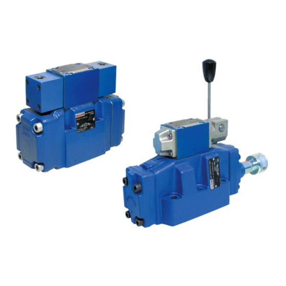
Product Picture
FigureCaption_Cover
tb0253+0254
H-4WPH10
.WPH10...QM
H-4WPH16
.WPH16...QM
H-4WPH22
.WPH22...QM
H-4WPH25
.WPH25...QM
H-4WPH32
.WPH32...QM
H-4WHH10
.WHH10...QM
H-4WHH16
.WHH16...QM
H-4WHH22
.WHH22...QM
H-4WHH25
.WHH25...QM
H-4WHH32
.WHH32...QM
H-4WM.H10
.WM.H10...QM
H-4WM.H16
.WM.H16...QM
H-4WM.H22
.WM.H22...QM
H-4WM.H25
.WM.H25...QM
H-4WM.H32
.WM.H32...QM
Product Picture
FigureCaption_Cover
Advertisement
Table of Contents

Related Manuals for Bosch WPH


Summary of Contents for Bosch WPH
- Page 1 3/2, 4/2 and 4/3 directional valves RE 24851-B/06.09 ProductName pilot operated English ProductDescription Type WPH, WHH, WMMH, WMDH, WMDAH, WMRH, and WMUH Operating instructions DocumentType Product Picture Product Picture Product Picture FigureCaption_Cover FigureCaption_Cover FigureCaption_Cover tb0253+0254 Applies to the following types:...
- Page 2 © This document, as well as the data, specifica- tions and other information set forth in it, are the exclusive property of Bosch Rexroth AG. It may not be reproduced or given to third parties without its consent.
-
Page 3: Table Of Contents
7 Commissioning ..................... 26 7.1 First commissioning; re-commissioning after extended standstill ... 26 8 Operation ....................... 27 8.1 Operating the manual override (only with valve types ...WPH...).... 27 8.2 Modifying the stroke ................28 9 Maintenance ....................29 9.1 Term definition ..................29 9.2 Cleaning and care ................... - Page 4 4/40 Bosch Rexroth AG W.H; WM.H | RE 24851-B/06.09 Contents 13 Extension and conversion ................36 13.1 Optional accessories................36 14 Troubleshooting .................... 37 14.1 How to proceed for troubleshooting ............37 15 Technical data ....................38 16 Appendix ......................39 16.1 Project/installation drawings ..............
-
Page 5: About This Document
RE 24851-B/06.09 | W.H; WM.H Bosch Rexroth AG 5/40 About this document 1 About this document These operating instructions are valid for Rexroth 3/2-, 4/2-, and 4/3 directional valves, pilot operated. These instructions contain important information on the safe and appropriate as- sembly, transport, commissioning, operation, maintenance, disassembly and simple troubleshooting of the valve. -
Page 6: Related Documents
6/40 Bosch Rexroth AG W.H; WM.H | RE 24851-B/06.09 General safety instructions About this document | General safety instructions Related documents The valve is a system component. Also observe the instructions for the other sys- tem components. Also observe the instructions in the following manuals: •... -
Page 7: Intended Use
Bosch Rexroth. After disassembly of the spool position monitoring, the complete valve may only be assembled and re-adjusted by authorized experts or by Bosch Rexroth. Improper use Any use of the valve other than described in section "2.1 Intended use" is consid- ered as improper. -
Page 8: Safety Instructions In This Document
8/40 Bosch Rexroth AG W.H; WM.H | RE 24851-B/06.09 General safety instructions Safety instructions in this document In these instructions, there are warnings before an instruction whenever there is a risk of personal injury or damage to property. The measures described for pre- venting these hazards must be observed. - Page 9 RE 24851-B/06.09 | W.H; WM.H Bosch Rexroth AG 9/40 General safety instructions • The valve is no safety device. The valve alone must not be assigned the hold- ing of a position; there must be another monitoring feature. • The valve could block in an undefined position due to internal pollution –...
-
Page 10: Obligations Of The Operator
Dispose of hydraulic fluid residues according to the applicable safety data sheets for hydraulic fluids. Obligations of the operator The operator of the valve from Bosch Rexroth is bound to provide for personnel training on a regular basis regarding the following subjects: •... -
Page 11: Safety Labels
The operator must provide personal protective equipment (e.g. gloves, safety shoes, safety goggles, overall, etc.). Touch guard As protection against the hot valve surfaces, Bosch Rexroth recommends the in- stallation of a touch guard so that unwanted contact with the hot surface can be avoided. -
Page 12: Product Description
12/40 Bosch Rexroth AG W.H; WM.H | RE 24851-B/06.09 Product description Product description Performance description See "Technical data sheet" The assignment of the valves to the technical data sheets is contained in table 2 on page 6. Device description See "Technical data sheet"... - Page 13 RE 24851-B/06.09 | W.H; WM.H Bosch Rexroth AG 13/40 Product description Fig. 2: Name plate size 16, 25, 32 Table 5: About the name plate Type of information Information or example Manufacturer's logo Rexroth R9012345678 Material no. of the valve (= order no.) e.g.:...
-
Page 14: Transport And Storage
The information on the weight of your valve is contained in the Technical data sheet. Transport damage must be reported within one week to Bosch Rexroth to the following address: Bosch Rexroth AG Service Industriehydraulik [Industrial hydraulics] Bürgermeister-Dr.-Nebel-Straße 8... -
Page 15: Transport By Hand
Type of attachment or pick-up of the load. Ensure that the lifting gear's lifting capacity is sufficient in order to transport the valve without risk. Use textile attachment devices - according to DIN EN 1492-2. More information regarding the transport is available from Bosch Rexroth. -
Page 16: Storage
Bran-O-Rost protective oil. • After opening the transport packaging, it must be closed properly again for the storage. In case of storage of more than six months or in case of sea transport, coordi- nation with Bosch Rexroth is required. -
Page 17: Assembly
RE 24851-B/06.09 | W.H; WM.H Bosch Rexroth AG 17/40 Assembly Assembly Unpacking Dispose of the packaging in accordance with the national regulations of your country. Risk of personal injuries and damage to property! In case of improper opening of the packaging, components of the valve may fall out and cause damage to the components or even injuries as the components may be sharp-edged, heavy, oily, unstable, loose and bulky. -
Page 18: Installation Conditions
18/40 Bosch Rexroth AG W.H; WM.H | RE 24851-B/06.09 Assembly Installation conditions For installing the product always observe the environmental conditions specified in the technical data (see "Technical data sheet"). Installation position See "Technical data sheet" The assignment of the valves to the technical data sheets is contained in ta- ble 2 on page 6. -
Page 19: Required Tools
In order to install the valve, you need standard tools only. Required accessories In order to assemble the valve, you need the following accessories, which are not included in the delivery and can be ordered from Bosch Rexroth. • Valve mounting screws Due to reasons of stability, only the following valve mounting screws have to be used. -
Page 20: Assembling The Valve
20/40 Bosch Rexroth AG W.H; WM.H | RE 24851-B/06.09 Assembly Assembling the valve Have sufficiently dimensioned collection containers, enough clean- ing cloths and medium-binding materials ready in order to collect or bind leaking medium. DANGER! Risk of personal injury and damage to property! Incorrectly assembled valves can cause substantial material damage and per- sonal injuries. - Page 21 WARNING! Risk of material damage and personal injuries due to improper installation! The use of mounting material not approved of by Bosch Rexroth and erroneous installation may result in damage to the valve, adjacent components, as well as personal injuries due to escaping pressurized hydraulic oil.
- Page 22 22/40 Bosch Rexroth AG W.H; WM.H | RE 24851-B/06.09 Assembly Hydraulic connection of the valve Depressurize the relevant part of the system. CAUTION! Risk of injury when assembling under pressure! If you fail to depressurize the product before starting the assembly, you may suf- fer injury and also damage the unit or system components.
-
Page 23: Connecting The Spool Position Monitoring
RE 24851-B/06.09 | W.H; WM.H Bosch Rexroth AG 23/40 Assembly Connecting the spool position monitoring The following description applies to the following valve types: ...QM..Also observe the information in the Technical data sheets. The assignment of the valves to the Technical data sheets is contained in table 2 on page 6. -
Page 24: Connecting The Pneumatic Control
24/40 Bosch Rexroth AG W.H; WM.H | RE 24851-B/06.09 Assembly Only the mating connectors specified in the "Technical data sheet" (RE 24830 and RE 08006) or mating connectors of the same type may be used. Observe the installation instructions printed on the packaging of the mating connector and the tightening torques specified there. -
Page 25: Connecting The Hydraulic Control
"Technical data sheet". The valve can be converted to other operating modes; this may, how- ever, only by done by the Bosch Rexroth Service or any other authorized Bosch Rexroth department. After a conversion of the pilot oil supply and/or return, the coded type designa- tion printed on the name plate of the valve does not specify the current status any more and must thus be corrected. -
Page 26: Commissioning
Check whether there is an internal leakage. This has to be done according to the possibilities offered by the hydraulic system. There may be an internal leakage due to the specific valve. This has, howev- er, no influence on the valve's functionality. For information regarding this topic, please contact Bosch Rexroth. -
Page 27: Operation
RE 24851-B/06.09 | W.H; WM.H Bosch Rexroth AG 27/40 Commissioning | Operation Operation Performing a functional test If possible, firstly check hydraulic functions in a controlled form and with low pressure; observe the operating instructions of the hydraulic system into which the valve has been installed. -
Page 28: Modifying The Stroke
28/40 Bosch Rexroth AG W.H; WM.H | RE 24851-B/06.09 Operation CAUTION! Risk of personal injury and damage to property! There is the risk of damaging the manual override. The manual override is only intended for short-term manual actuation and must not be brought into a certain spool position for a longer period or permanently us- ing mechanical equipment. -
Page 29: Maintenance
RE 24851-B/06.09 | W.H; WM.H Bosch Rexroth AG 29/40 Operation | Maintenance Maintenance Modify stroke by rotating the adjustment spindle ( – In order to reduce the stroke, turn the adjustment spindle ( to the right (clockwise). – In order to increase the stroke, turn the adjustment spindle ( to the left (counter-clockwise). -
Page 30: Cleaning And Care
30/40 Bosch Rexroth AG W.H; WM.H | RE 24851-B/06.09 Maintenance Cleaning and care CAUTION! Penetrating dirt and liquids will cause faults! Safe function of the valve is no longer ensured. Always provide for absolute cleanness when working on the valve. -
Page 31: Repair
Plug and subsequently screw the mating connector (on) to the connector of the spool position monitoring. Repair Bosch Rexroth offers a wide range of repair services for the valve. Only use genuine spare parts from Bosch Rexroth for repairing the Rexroth product. -
Page 32: Spare Parts
Please send your spare parts order to the Bosch Rexroth service next to you or directly to the headquarters (see section 16.2 "Address directory" on page 39). - Page 33 RE 24851-B/06.09 | W.H; WM.H Bosch Rexroth AG 33/40 Maintenance Table 13: NBR seal kits up to 350 bar Size Material no. Size 10 R961004011 Size 16 R961004014 Size 25 (7X) R961004016 Size 25 (6X) R961004018 Size 32 R961004020 Table 14:...
-
Page 34: Decommissioning
34/40 Bosch Rexroth AG W.H; WM.H | RE 24851-B/06.09 Decommissioning Decommissioning | Disassembly and replacement Decommissioning The valve is a component that does not require decommissioning. As a result, this chapter of the instructions does not contain any information. For details about how to disassemble or replace the valve, please refer to chapter "11 Disassembly and replacement". -
Page 35: Disposal
Please observe the following supplied notes for the environmentally-friendly disposal of the valve. 12.2 Return to Bosch Rexroth AG The products manufactured by us can be returned to us for disposal purposes at no costs. However, the precondition is that there are no spurious adherences or any other contamination. -
Page 36: Recycling
36/40 Bosch Rexroth AG W.H; WM.H | RE 24851-B/06.09 Extension and conversion Disposal | Extension and conversion 12.5 Recycling Due to the high share of metal, the products can mostly be recycled. In order to achieve an ideal metal recovery, disassembly into individual assemblies is re- quired. -
Page 37: Troubleshooting
RE 24851-B/06.09 | W.H; WM.H Bosch Rexroth AG 37/40 Extension and conversion | Troubleshooting Troubleshooting Special tool for the manual override with valve type ..WPH... Table 17: Special tool Valve type Material no. For all types with manual override R900024943... -
Page 38: Technical Data
"8.1 Operating the manual override (only with valve types ...WPH...)" on page 27. If the spool cannot be released, remove the valve and replace it by a new valve. -
Page 39: Appendix
RE 24851-B/06.09 | W.H; WM.H Bosch Rexroth AG 39/40 Appendix Appendix 16.1 Project/installation drawings See "Technical data sheet". The assignment of the valves to the Technical data sheets is contained in table 2 on page 6. 16.2 Address directory Please refer to http://www.boschrexroth.com. for addresses of foreign subsidiaries. - Page 40 Bosch Rexroth AG Industrial Hydraulics Zum Eisengießer 1 97816 Lohr am Main Germany Phone +49 (93 52) 18-0 +49 (93 52) 18-40 documentation@boschrexroth.de www.boschrexroth.de Printed in Germany RE 24851-B/2009-06...