Table of Contents
Advertisement
Quick Links
Specifications
Power Source
Power Consumption
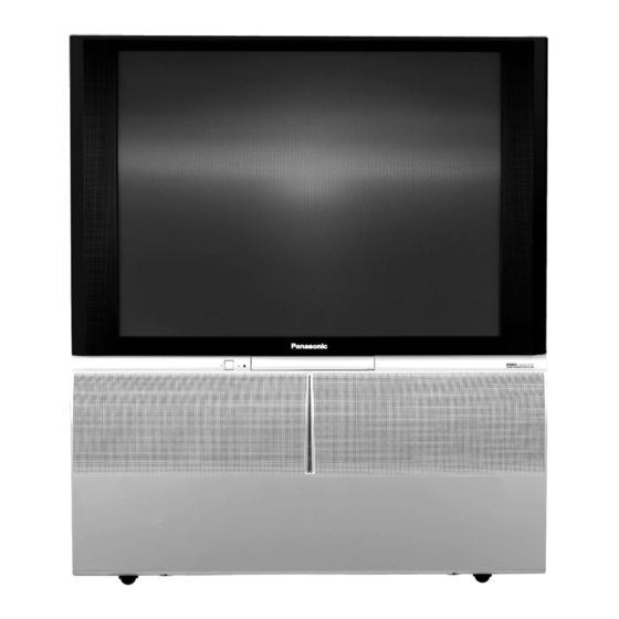
Dimensions (W × H × D)
Mass (Weight)
Remote control Transmitter
Receiving System
TX-43P950M / TX-51P950M
AC 220 - 240 V, 50 / 60 Hz
Stand-by condition: less than 1W
Normal viewing: 165 W(43"),170W (51")
TX-43P950M / X
1095 mm × 1267.5 mm × 518 mm
58 kg (Net)
N2QAJB000109
R6 (AA) Battery × 2
Projection Television
TX-51P950M
TX-51P950X
TX-43P950M
TX-43P950X
GP11N-VP
TX-43P950X/TX-51P950X
AC 220 - 240 V, 50 / 60 Hz
Stand-by condition: 0.5 W
Normal viewing : 165W(43"),170W(51")
TX-51P950M/X
1298 mm × 1394 mm × 518 mm
68 kg (Net)
© 2005 Matsushita Electric Industrial Co., Ltd. All
rights
reserved.
distribution is a violation of law.
ORDER NO.PAVCSH200507005C3
Unauthorized
copying
and
Advertisement
Table of Contents

Related Manuals for Panasonic TX-51P950M


Summary of Contents for Panasonic TX-51P950M
- Page 1 Projection Television TX-51P950M TX-51P950X TX-43P950M TX-43P950X GP11N-VP Specifications TX-43P950M / TX-51P950M TX-43P950X/TX-51P950X Power Source AC 220 - 240 V, 50 / 60 Hz AC 220 - 240 V, 50 / 60 Hz Power Consumption Stand-by condition: less than 1W Stand-by condition: 0.5 W Normal viewing: 165 W(43"),170W (51")
- Page 2 TX-51P950M / TX-51P950X / TX-43P950M / TX-43P950X Receiving Channels Regular TV VHF BAND 2-12 (PAL/SECAM B, K1) 0-12 (PAL B AUST.) 1-9 (PAL B N.Z) 1-12 (PAL/SECAM D) 1-12 (NTSC M Japan) 2-13 (NTSC M U.S.A) UHF BAND 21-69 (PAL G, H, I/SECAM G, K, K1) 28-69 (PAL AUST.)
-
Page 3: Table Of Contents
TX-51P950M / TX-51P950X / TX-43P950M / TX-43P950X AV1 IN (Rear): S Video, Video, Audio L/R terminals AV2 IN (Rear): Video or Y/ P , Audio L/R terminals AV3 IN (Front): S Video, Video, Audio L/R terminals AV4 IN (Rear): Video or Y/ P... - Page 4 TX-51P950M / TX-51P950X / TX-43P950M / TX-43P950X 13.9. DG-Board (1 of 6) Schematic Diagram 13.18. LG-Board Schematic Diagram 13.10. DG-Board (2 of 6) Schematic Diagram 13.19. LR-Board Schematic Diagram 13.11. DG-Board (3 of 6) Schematic Diagram 14 Parts Location 13.12. DG-Board (4 of 6) Schematic Diagram 15 Packing Exploded View 13.13.
-
Page 5: Safety Precautions
TX-51P950M / TX-51P950X / TX-43P950M / TX-43P950X 1 Safety Precautions 1.1. General Guide Lines 1. It is advisable to insert an isolation transformer in the AC supply before servicing a hot chassis. 2. When servicing, observe the original lead dress, especially the lead dress in the high voltage circuits. -
Page 6: Chassis Board Layout
TX-51P950M / TX-51P950X / TX-43P950M / TX-43P950X 2 Chassis Board Layout Board-Name Function A-Board Main Signal, Digital Converter,Line Filter D-Board Deflection, High Voltage LR-Board CRT Drive (R) LG-Board CRT Drive (G) LB-Board CRT Drive (B) H-Board Rear terminal DG-Board Digital Core,MPU,AV Switch... -
Page 7: Disassembly For Service
TX-51P950M / TX-51P950X / TX-43P950M / TX-43P950X 3 Disassembly for Service This flowchart indicates disassembly items of the cabinet parts and circuit boards in order to find the items necessary for servicing, when reassembling, perform the procedures in the reverse order. -
Page 8: Cabinet Side (L, R)
TX-51P950M / TX-51P950X / TX-43P950M / TX-43P950X Note: Board ground wires may have to be disconnected to disassemble some boards. All ground wires must be reconnected using jumper leads if necessary before power is applied to Receiver for service. 3.2. -
Page 9: Cabinet (Top)
TX-51P950M / TX-51P950X / TX-43P950M / TX-43P950X 3.6. Speaker (Top Cabinet) 3.5. Cabinet (Top) 1. Remove (12) Screws. 3.7. Screen 1. Remove (20) nails, and remove (2) Screen Holders (vertical side) and (4) Screen Holders (horizontal side). -
Page 10: Mirror
TX-51P950M / TX-51P950X / TX-43P950M / TX-43P950X 3.8. Mirror 3.10. Rear Cover (Bottom) 1. Remove (3) screws. 1. Remove (15) screws. 2. Remove (1) screw. 3.9. Rear Cover (Top) 1. Remove the Top Cabinet. 2. Remove (2) screws. -
Page 11: Disassembly For Crt Removal
TX-51P950M / TX-51P950X / TX-43P950M / TX-43P950X 3.11. Disassembly For CRT Removal To facilitate CRT replacement, the complete CRT mounting chassis does not need to be removed. 1. Remove the Screen Frame Ass´y, Decorative Panel and the Bottom Rear Cover Ass´y. ( See Disassemble for Service ). -
Page 12: Service Hints
TX-51P950M / TX-51P950X / TX-43P950M / TX-43P950X 4 Service Hints 4.1. Service position for Main PART No. :GP11(N)-2 chassis 1. Remove the Rear Cover (Bottom) by removing (15) screws and (1) screws around its perimeter. 2. Remove lead wires and bundles from holders as necessary. -
Page 13: Service Position For Ka-Board
TX-51P950M / TX-51P950X / TX-43P950M / TX-43P950X 4.4. Service Position for KA-Board 4.5. VOLTAGE CHART 1. Remove the Speaker Grille. D-BOARD 2. Remove the Terminal Door by (4) screws. A-BOARD SUPPLY TEST POINT VOLTAGE 12V ~ GND A5 PIN9 11.9 ± 0.45V... -
Page 14: Self Check
TX-51P950M / TX-51P950X / TX-43P950M / TX-43P950X 5 Self Check 1. Self-Check is used to automatically check the bus lines and hexadecimal code of the TV set. 2. To get into the Self -Check mode press the down ( ) button on the customer controls at the front of the set, at the same time pressing the OFF Timer button on the remote control, and the screen will show : If the CCU ports have been checked and found to be incorrect or not located then “--”... -
Page 15: Service Mode Function
TX-51P950M / TX-51P950X / TX-43P950M / TX-43P950X 6 Service Mode Function MPU controls the functions switching for each IICs through IIC bus in this chassis. The following setting and adjustment can be adjusted by remote control in Service Mode. 6.1. - Page 16 TX-51P950M / TX-51P950X / TX-43P950M / TX-43P950X...
-
Page 17: Option Descrition
TX-51P950M / TX-51P950X / TX-43P950M / TX-43P950X 6.3. Option Descrition... - Page 18 TX-51P950M / TX-51P950X / TX-43P950M / TX-43P950X...
- Page 19 TX-51P950M / TX-51P950X / TX-43P950M / TX-43P950X...
-
Page 20: Crt Set Up
TX-51P950M / TX-51P950X / TX-43P950M / TX-43P950X 7 CRT Set Up Caution: 7.2. Electrical Focus Adjustment Insure yoke plugs on the A-Board are reconnected before 1. Receive a monoscope pattern. turning the Receiver ON to prevent damage to the horizontal output transistor and/or CRTs. -
Page 21: Centering Magnet Adjustment
TX-51P950M / TX-51P950X / TX-43P950M / TX-43P950X 7.4. Centering Magnet Adjustment 1. Receive a monoscope pattern. 2. Set that Fine convergence data (Service mode1) is clear (no correction). 3. Set that V-Pos data (Service mode1) is [130]. 4. Set that H-Pos data (Service mode1) is [954]. -
Page 22: Alignment Magnet Adjustment
TX-51P950M / TX-51P950X / TX-43P950M / TX-43P950X 7.5. Alignment magnet Adjustment Preparation: 1. Receive an cross hatch pattern with dots (pincushion). 2. Loosen the centering magnets screws. 3. Position the longer tab of the four-pole magnet to 90 degrees (uncorrected position). -
Page 23: Deflection Adjustment
TX-51P950M / TX-51P950X / TX-43P950M / TX-43P950X 8 Deflection Adjustment 8.1.3. V-Amp, V-Linear and V-Pos Caution 1. The following adjustment have to be carried out one Adjustment with PAL signal (100i/50p) and with NTSC signal 1. Adjust Vertical amplitude for 2.3 ± 0.1 division of a scale by (60p/120i). -
Page 24: Pal 100Hz V Comp Mode (100I)
TX-51P950M / TX-51P950X / TX-43P950M / TX-43P950X 8.2. PAL 100Hz V Comp mode 8.2.3. V-Amp, V-Linear and V-Pos Adjustment (100i) 1. Adjust Vertical amplitude for 2.0 ± 0.1 division of a scale by 8.2.1. Preparation V-Amp control. 1. Receive PAL monoscope pattern. -
Page 25: Pal Progressive Mode (50P)
TX-51P950M / TX-51P950X / TX-43P950M / TX-43P950X 8.3. PAL Progressive mode (50p) 8.4. NTSC Progressive mode (60p) 8.3.1. Preparation 8.4.1. Preparation 1. Receive PAL monoscope pattern. 1. Receive NTSC monoscope pattern. 2. Set scan mode to progressive. 2. Set scan mode to Progressive. -
Page 26: 525I/525P Deflection Adjustment / Confirmation
TX-51P950M / TX-51P950X / TX-43P950M / TX-43P950X 8.4.3. V-Amp, V-Linear and V-Pos 8.5. 525i/525p Deflection Adjustment Adjustment / Confirmation 1. Adjust Vertical amplitude for 2.3 ± 0.1 division of a scale by 8.5.1. V / H-Deflection confirmation V-Amp control. 1. Receive 525i or 525p signal. -
Page 27: Adjustment Procedure
TX-51P950M / TX-51P950X / TX-43P950M / TX-43P950X 9 Adjustment Procedure 9.1. Cut off Adjustment Preparation Picture Menu : Dynamic WB-B-G-ST1 : 255 C Temp : Standard High-R/B : 128 AI : ON Low-RGB : 640 P-NR : AUTO Scan Mode : 100Hz (PAL) -
Page 28: Sub Contrast Adjustment
TX-51P950M / TX-51P950X / TX-43P950M / TX-43P950X 9.2. Sub Contrast Adjustment Preparation Picture Menu : Dynamic C Temp : Standard High-R/B : 128 AI : ON Low-G : 640 P-NR : AUTO Low-R/B :***(Adjustment value) Scan Mode : 100Hz (PAL) -
Page 29: Blue Focus / Gamma Adjustment
TX-51P950M / TX-51P950X / TX-43P950M / TX-43P950X 9.4. Blue Focus / Gamma Adjustment Preparation Picture Menu : Dynamic WB-B-G-ST1 : 100 C Temp : Standard B-Limit : 255 AI : ON P-NR : AUTO Scan Mode : 100Hz (PAL) Adjustment 1. -
Page 30: Sub Bright Adjustment
TX-51P950M / TX-51P950X / TX-43P950M / TX-43P950X 43 inch model 9.6. Sub Bright Adjustment Preparation Picture Menu : Dynamic P-NR : AUTO C Temp : Dynamic Scan Mode : 100Hz (PAL) AI : ON Cut off and White Balance Adjustment has been adjusted Adjustment 1. -
Page 31: Convergence Adjustment
TX-51P950M / TX-51P950X / TX-43P950M / TX-43P950X 10 Convergence Adjustment The convergence adjustment is set separately for each Adjust the convergence for each of the 50/100Hz and 50/100Hz/ 60/100Hz input (NTSC, PAL/ SECAM). The 60/120Hz inputs so that they are aligned with the other colours. -
Page 32: Convergence Adjustment Procedure
TX-51P950M / TX-51P950X / TX-43P950M / TX-43P950X 10.2. Convergence Adjustment Procedure 1. Input a monoscope pattern of PAL. 2. Enter the Service Mode1. 3. Select the Coarse Convergence by pushing "RED" or "GREEN" buttons. Then push "YELLOW" button, and push Position and [N] buttons to set the data to zero. -
Page 33: Coarse Convergence Adjustment Mode
TX-51P950M / TX-51P950X / TX-43P950M / TX-43P950X 10.3. Coarse Convergence Adjustment mode 10.3.1. Green Coarse Convergence Adjustment 10.3.1.1. Reparation Push the "SURROUND" button, and select the Green Adjustment mode.Push the "2" button, and select the "Border and Cross" pattern.Push the "R-TUNE" button, and select the "Green" colour. - Page 34 TX-51P950M / TX-51P950X / TX-43P950M / TX-43P950X 10.3.1.3. "G-SIZE (H)" adjustment Push the "TV/AV" buttons, and select the "G-SIZE (H)".Push the "Volume up/down" buttons, and adjust the boarder line on either side of test pattern is aligned with the edge of the screen frame.
- Page 35 TX-51P950M / TX-51P950X / TX-43P950M / TX-43P950X 10.3.1.7. "G-CORNER" adjustment Push the "TV/AV" buttons, and select the "G-CORNER".Push the "Volume up/down" buttons, and adjust the "G-CORNER" to become the following figure. 10.3.1.8. "G-KEY" adjustment Push the "TV/AV" buttons, and select the "G-KEY".Push the "Channel up/down" buttons, and adjust the "G-KEY" refer to following figure.
- Page 36 TX-51P950M / TX-51P950X / TX-43P950M / TX-43P950X 10.3.2. Red Coarse Convergence Adjustment 10.3.2.1. Reparation Push the "SURROUND" button, and select the Red Adjustment mode.Push the "2" button, and select the "Border and Cross" pattern.Push the "R-TUNE" button, and select the "Yellow" colour.Push the "POSITION" button, and adjust the "R-STATIC" so that the Red color of pattern is aligned with Green colour of pattern.
- Page 37 TX-51P950M / TX-51P950X / TX-43P950M / TX-43P950X 10.3.2.6. "R-LINEAR" adjustment Push the "TV/AV" buttons, and select the "R-LINEAR".Push the "Volume up/down" buttons, and adjust the "R-LINEAR". (Refer to Fig. C.) 10.3.2.7. "R-PIN (V)" adjustment Push the "TV/AV" buttons, and select the "R-PIN".Push the "Channel up/down" buttons, and adjust the "R-PIN (V)". (Refer to Fig.
- Page 38 TX-51P950M / TX-51P950X / TX-43P950M / TX-43P950X 10.3.3.6. "B-LINEAR" adjustment Push the "TV/AV" buttons, and select the "B-LINEAR".Push the "Volume up/down" buttons, and adjust the "B-LINEAR". (Refer to Fig. C.) 10.3.3.7. "B-PIN (V)" adjustment Push the "TV/AV" buttons, and select the "B-PIN".Push the "Channel up/down" buttons, and adjust the "B-PIN (V)" (Refer to Fig.
-
Page 39: Fine Convergence Adjustment
TX-51P950M / TX-51P950X / TX-43P950M / TX-43P950X 10.4. Fine Convergence Adjustment 10.4.1. Green Convergence Adjustment 8. Use the Position Buttons to adjust each point so that the Green Crosshatch Pattern is aligned with the vertical and 1. Select the "G-LINE CURSOR" mode by pushing "TV/AV"... - Page 40 TX-51P950M / TX-51P950X / TX-43P950M / TX-43P950X 10.4.3. Blue Convergence Adjustment 1. Push the "R-TUNE" button twice and change to the Blue Adjustment of cyan Colour. 2. Repeat the same steps described for the Green Conv.Adj. in 1~16 to perform the Blue Convergence Adjustment.
- Page 41 TX-51P950M / TX-51P950X / TX-43P950M / TX-43P950X Fine Convergence Control Chart...
- Page 42 TX-51P950M / TX-51P950X / TX-43P950M / TX-43P950X...
-
Page 43: Location Of Lead Wiring
TX-51P950M / TX-51P950X / TX-43P950M / TX-43P950X 11 Location of Lead Wiring 11.1. Location of Lead Wiring (1) - Page 44 TX-51P950M / TX-51P950X / TX-43P950M / TX-43P950X INSERTION OF CONNECTOR LR1, LR2, LG1, LG2, LG3, LG4, LG5, LG6, LG7, LB1, LB2, LR20, LG20, LB20 NOTICE FOR WORE DRESSING 1. Confirm that the lead line isn’t hitting the metallic part of the neck print after CRT neck print (R, G, B) insertion.
- Page 45 TX-51P950M / TX-51P950X / TX-43P950M / TX-43P950X 11.2. Location of Lead Wiring (2) The Anode Lead 1. It inserts Anode lead tip in the back to FBT (the fly background transformer), and it makes turn on the right and it locks it.
- Page 46 TX-51P950M / TX-51P950X / TX-43P950M / TX-43P950X INSERTION OF CONNECTOR A6, A7, A21, A22, A23, A49, Anode distributor (R, G, B, FBT), D8, D5, DY (R, G, B), CY (R, G, B), D30, P1, P2, P4, Focus Pack (R) NOTICE FOR WIRE DRESSING...
-
Page 47: Conductor Views
TX-51P950M / TX-51P950X / TX-43P950M / TX-43P950X 12 Conductor Views 12.1. A-Board... - Page 48 TX-51P950M / TX-51P950X / TX-43P950M / TX-43P950X A-Board(FOIL SIDE) TNPH0625 TX-43P950M/X TX-51P950M/X TX-43P950M/X TX-51P950M/X A-Board TNPH0625 A-Board TNPH0625...
-
Page 81: Packing Exploded View
TX-51P950M / TX-51P950X / TX-43P950M / TX-43P950X 15 Packing Exploded View... - Page 82 TX-51P950M / TX-51P950X / TX-43P950M / TX-43P950X...
-
Page 83: Mechanical Replacement Parts List
TX-51P950M / TX-51P950X / TX-43P950M / TX-43P950X 16 Mechanical Replacement Parts List 51" mechanical replacement parts list Ref. No. Part No. Part Name & Description Remarks TPC0A48703 CARTON BOX(TX-51P950XA) Ref. No. Part No. Part Name & Description Remarks TPC0A48704 CARTON BOX(TX-51P950XB) - Page 84 TX-51P950M / TX-51P950X / TX-43P950M / TX-43P950X Ref. No. ITEM ITEM DESCRIPTION Remarks TKK0A8527 REAR COVER TKK0A8531 LED PANEL TKP0AB1604 REAR AV BRACKET TKP0AB2201 TKP0AB2301 DOOR TKU0A2404A BACK COVER (BOTTOM) TKU0A3701 BACK COVER TKX0A1701-1 CABINET(LEFT) TKX0A1801-1 CABINET(RIGHT) TKZ0A8808 SOLEPLATE TKZ0A8813...
-
Page 85: Electrical Replacement Parts List
TX-51P950M / TX-51P950X / TX-43P950M / TX-43P950X 17 Electrical Replacement Parts List 17.1. Replacement Parts List Notes... -
Page 86: Electrical Replacement Parts List
TX-51P950M / TX-51P950X / TX-43P950M / TX-43P950X 17.2. Electrical Replacement Parts List Ref. No. Part No. Part Name & Remarks Ref. No. Part No. Part Name & Remarks Description Description IC001 AN78M05LB D357 MA2C165001VT DIODE IC054 C0DAAZG00014 IC D360 MA2C18800E... - Page 87 TX-51P950M / TX-51P950X / TX-43P950M / TX-43P950X Ref. No. Part No. Part Name & Remarks Ref. No. Part No. Part Name & Remarks Description Description D834 B0EAEV000001 DIODE Q401 2SD0601A0L TRANSISTOR D835 B0JANG000003 DIODE Q402 2SB0709A0L TRANSISTOR D837 B0JAMG000025 DIODE...
- Page 88 TX-51P950M / TX-51P950X / TX-43P950M / TX-43P950X Ref. No. Part No. Part Name & Remarks Ref. No. Part No. Part Name & Remarks Description Description Q4416 XN0560100L TRANSISTOR L705 G0C101K00023 COIL Q4417 XN0560100L TRANSISTOR L706 G0A222DA0017 COIL Q4418 XN0560100L TRANSISTOR...
- Page 89 TX-51P950M / TX-51P950X / TX-43P950M / TX-43P950X Ref. No. Part No. Part Name & Remarks Ref. No. Part No. Part Name & Remarks Description Description L4016 EXC3BB221H COIL R358 RD16ST473J C 47K OHM J 1/4W L4205 J0JCC0000241 COIL R359 RD16ST563J...
- Page 90 TX-51P950M / TX-51P950X / TX-43P950M / TX-43P950X Ref. No. Part No. Part Name & Remarks Ref. No. Part No. Part Name & Remarks Description Description R513 RD16ST203J C 20K OHM J 1/4W R914 RD16ST562J C 5.6K OHM J 1/4W R514...
- Page 91 TX-51P950M / TX-51P950X / TX-43P950M / TX-43P950X Ref. No. Part No. Part Name & Remarks Ref. No. Part No. Part Name & Remarks Description Description R1152 ERJ3GEYJ103V M 10K OHM J 1/16W R2026 ERJ3GEYJ221V M 220 OHM J 1/16W R1153...
- Page 92 TX-51P950M / TX-51P950X / TX-43P950M / TX-43P950X Ref. No. Part No. Part Name & Remarks Ref. No. Part No. Part Name & Remarks Description Description R3071 ERJ3GEYJ221V M 220 OHM J 1/16W R4080 ERJ3EKF4700V M 470 OHM F 1/16W R3072...
- Page 93 TX-51P950M / TX-51P950X / TX-43P950M / TX-43P950X Ref. No. Part No. Part Name & Remarks Ref. No. Part No. Part Name & Remarks Description Description R4429 ERJ3GEYJ472V M 4.7K OHM J 1/16W R4535 ERJ3EKF75R0V M 75 OHM F 1/16W R4430 ERJ3EKF6341V M 6.34 OHM F 1/16W...
- Page 94 TX-51P950M / TX-51P950X / TX-43P950M / TX-43P950X Ref. No. Part No. Part Name & Remarks Ref. No. Part No. Part Name & Remarks Description Description R7038 RSS2GT121J M 120 OHM J 2W R7703 ERJ6ENF3300V M 330 OHM 1/10W R7039 RSS2GT121J...
- Page 95 TX-51P950M / TX-51P950X / TX-43P950M / TX-43P950X Ref. No. Part No. Part Name & Remarks Ref. No. Part No. Part Name & Remarks Description Description R7797 RD16ST333J C 33K OHM J 1/4W JA25 ERJ8GEY0R00V M 0 0HM 1/10W R7798 RD16ST472J C 4.7K OHM J 1/4W...
- Page 96 TX-51P950M / TX-51P950X / TX-43P950M / TX-43P950X Ref. No. Part No. Part Name & Remarks Ref. No. Part No. Part Name & Remarks Description Description JS4424 ERJ3GEY0R00V M 0 OHM J 1/16W R4408 ERJ3GEY0R00V M 0 OHM J 1/16W JS4425...
- Page 97 TX-51P950M / TX-51P950X / TX-43P950M / TX-43P950X Ref. No. Part No. Part Name & Remarks Ref. No. Part No. Part Name & Remarks Description Description C141 MCJ2VB1H103K C 0.01UF K 50V C806 ECQU2A224MNB P 0.22UF M 250V C142 SKP471M1CF11 E 470UF 16V...
- Page 98 TX-51P950M / TX-51P950X / TX-43P950M / TX-43P950X Ref. No. Part No. Part Name & Remarks Ref. No. Part No. Part Name & Remarks Description Description C1109 ECJ1VB1C104K C 0.1UF K 16V C2025 ECJ2VF1C104Z C 0.1UF Z 16V C1111 ECJ1VC1H151J C 150PF J 50V...
- Page 99 TX-51P950M / TX-51P950X / TX-43P950M / TX-43P950X Ref. No. Part No. Part Name & Remarks Ref. No. Part No. Part Name & Remarks Description Description C3053 MCJ2VB1H562K C 5600PF K 50V C4069 ECJ1VF1C104Z C 0.1UF Z 16V C3106 MCJ2VB1H562K C 5600PF K 50V C4070 ECJ1VF1C104Z C 0.1UF Z 16V...
- Page 100 TX-51P950M / TX-51P950X / TX-43P950M / TX-43P950X Ref. No. Part No. Part Name & Remarks Ref. No. Part No. Part Name & Remarks Description Description C4425 ECJ1VF1H104Z C 0.1UF Z 50V C4534 ECJ1VF1C104Z C 0.1UF Z 16V C4426 ECJ1VB1C104K C 0.1UF K 16V...
- Page 101 TX-51P950M / TX-51P950X / TX-43P950M / TX-43P950X Ref. No. Part No. Part Name & Remarks Ref. No. Part No. Part Name & Remarks Description Description C7009 TKP101M1VE11 E 100UF 35V C7161 ECJ1VF1H104Z C 0.1UF Z 50V C7010 TKP101M1VE11 E 100UF 35V C7162 ECJ1VF1H104Z C 0.1UF Z 50V...
- Page 102 TX-51P950M / TX-51P950X / TX-43P950M / TX-43P950X Ref. No. Part No. Part Name & Remarks Ref. No. Part No. Part Name & Remarks Description Description LF801 ELF24V018A FILTER K1KA03AA0334 CONNECTOR LF870 ELF24V018A FILTER or LCL-35-001 LF872 ELF24V018A FILTER or LCL-35-001...