
Related Manuals for LG MASTER-K200S Series


Summary of Contents for LG MASTER-K200S Series
- Page 1 User’s Manual LG Programmable Logic Controller G3F-DA3V GLOFA G3F-DA3I MASTER-K G4F-DA3V G4F-DA3I G4F-DA2V G4F-DA2I G6F-DA2V G6F-DA2I LG Industrial Systems...
- Page 2 SAFETY PRECAUTIONS Be sure to read carefully the safety precautions given in data sheet and user’s manual before operating the module and follow them. The precautions explained here only apply to the G3F-DA3V/G3F-DA3I, G4F-DA3V/G4F-DA2V, G4F-DA3I/G4F- DA2I, G6F-DA2V/G6F-DA2I (hereafter, called D/A conversion module) For safety precautions on the PLC system, see the GLOFA GM3, GM4, GM6 User ’...
- Page 3 Installation Precautions Wiring Precautions CAUTION CAUTION ▶ Operate the PLC in the environ- ▶ When grounding a FG terminal, ment conditions given in the be sure to provide class 3 general specifications. grounding which is dedicated to ▶ If operated in other environment the PLC.
-
Page 4: Table Of Contents
◎ CONTENTS ◎ Chapter 1. INTRODUCTION 1.1 Features · · · · · · · · · · · · · · · · · · · · · · · · · · · · · · · · · · · · · · · · · · · · · · · · · · · · · · · · · · · · · · · · · · · · · · · · · · · · · · · · · · · · · · · · · · · · · · · · · · · · · · · · · · · · · · · · · · · · · · · · · · · · · · · · · · · · · · · · · · · · · · · · · · · · · · · · · · · · · · · · ·1-1 Glossary·... - Page 5 4.2.2 Module Write_Single Type (G3F-DA3V,G3F -DA3I,G4F-DA3V,G4F-DA3I : DA3WR, G4F-DA2V,G4F-DA2I,G6F-DA2V,G6F-DA2I : DA2WR) · · · · · · · · · · · · · · · · · · · · · · · · · · · · · · · · · · · · · · · · · · · · · · · · · · · · · · · · · · · · · · · · · · · · · · · · · · · · · · · · ·4-3 Remote Function Block ·...
-
Page 6: Chapter 1. Introduction
Chapter 1. INTRODUCION Chapter 1. INTRODUCTION The G3F-DA3V/G3F-DA3I, G4F-DA3V/G4F-DA3I, the G4F-DA2V/G4F-DA2I and G6F-DA2V/G6F-DA2I are digital/analog conversion modules for use with the GLOFA PLC GM1/2/3/4/6 series CPU module and the MASTER-K200S/300S/1000S series CPU module. (Hereafter the G3F-DA3V/G3F-DA3I, G4F-DA3V/G4F-DA3I, G4F-DA2V/G4F-DA2I and G6F-DA2V/G6F-DA2I are called the D/A conversion module) The D/A conversion module is to convert a 16-bit, signed BIN digital value into an analog output signal (voltage or current). -
Page 7: D-Digital Value
Chapter 1. INTRODUCION Analog value is a sequentially changing value such as voltage, current, temperature, speed, pressure, flux, etc. Temperature, for example, is sequentially changing according to the time. Because this temperature is not inputted on the PLC directly, the same analog value of DC voltage (0 to 10V) or current (4 to 20mA) in accordance with the temperature should be input on the PLC through transducer. - Page 8 Chapter 1. INTRODUCION Digital/analog conversion module allows digital value of the CPU to be converted into an analog value and to be output externally. Digital input value of 0 leads to analog output value of 0V and 4000 leads to 10V. Digital input value of 1 is equal to 2.5mV. 2) Voltage output - G4F-DA3V/G4F-DA2V/G6F-DA2V 5 ㎷...
-
Page 9: Chapter 2. Specifications
Chapter 2. SPECIFICATIONS Chapter 2. SPECIFICATIONS 2.1 General Specifications Table 2.1 shows the common specifications of the GLOFA GM series and the MASTER -K series. Reference Items Specifications Specification Operating ambient 0 ~ 55℃ temperature Storage ambient -25 ~ 70℃ temperature Operating ambient 5 ~ 95%RH, non-condensing... -
Page 10: Performance Specifications
Chapter 2. SPECIFICATIONS 2.2 Performance Specifications Table 2..2 and table 2.3 shows performance specification of D/A conversion module. Specifications Items G4F-DA3I G4F-DA2I G4F-DA3V G4F-DA2V I/O points 16 points Digital input 16bit(data part :1 2bits)signed binary DC 4 ~ 20mA -10 ~ 10 VDC Analog output (External load resistance less than 510 Ω... - Page 11 Chapter 2. SPECIFICATIONS Specifications Items G3F-DA3I G6F-DA2I G3F-DA3V G6F-DA2V I/O points 16 points Digital input 16bit(data part :1 2bits)signed binary 0~10 VDC -10~10 VDC DC 4~20mA (External load (External load Analog output resistance : resistance : (External load resistance less than 510Ω) 2KΩ~1MΩ) 2KΩ~1MΩ) Max.
-
Page 12: Names Of Parts And Functions
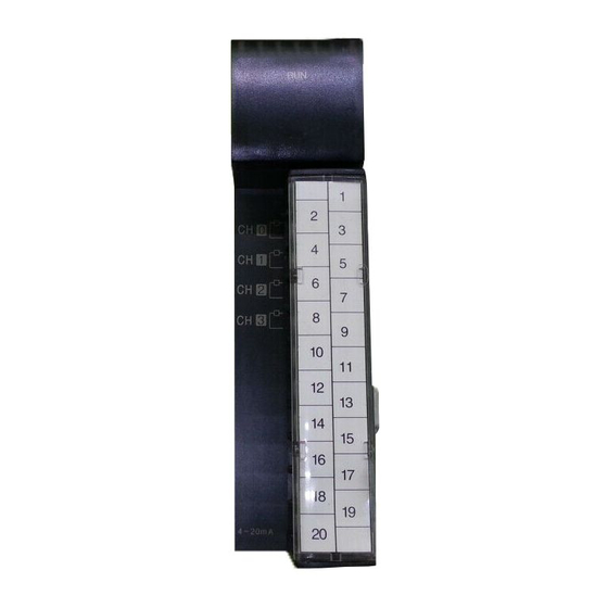
Chapter 2. SPECIFICATIONS 2.3 Names of Parts and Functions Names of parts and fu nctions are shown as below. 1) G4F-DA3V/G4F-DA2V/G4F-DA3I/G4F-DA2I G4F -DA3V G4F -DA2V G4F -DA3I G4F -DA2I G4F-DA3V G4F-DA2V G4F-DA3I G4F-DA2I ← ← ← ← ↑ ↑ ↑ ↑... - Page 13 Chapter 2. SPECIFICATIONS 2) G3F-DA3V/G3F-DA3I G3F-DA3V G3F-DA3I G3F-DA3V G3F-DA3I ② DC24V Descriptions RUN LED ① Indicates the operating condition of the D/A conversion module * On: Normal operation * Off : 5 VDC power off or D/A conversion module fault External input terminal block ②...
- Page 14 Chapter 2. SPECIFICATIONS 3) G6F-DA2V/G6F-DA2I G6F-DA2V G6F-DA2I ① G6F-DA2V G6F-DA2I G6F-DA2V G6F-DA2I ② ② -10~+ 1 0V 4 ~ 20 ㎃ Descriptions RUN LED ① Indicates the operating condition of the D/A conversion module * On: Normal operation * Off : 5 VDC power off or D/A conversion module fault External input terminal block ②...
-
Page 15: Input/Output Conversion Characteristics
Chapter 2. SPECIFICATIONS 2.4 Input/Output Conversion Characteristics I/O characteristics are displayed as a slant of the line connecting offset value and gain value in converting an digital signal from the external PLC into an analog signal(voltage or current). Offset value and Gain value of D/A converter are fixed and should not be modified. Input/ output conversion characteristic example is shown on Fig 2.1 20. -
Page 16: Chapter 3. Installation And Wiring
Chapter 3. INSTALLATION AND WIRING CHAPTER 3. INSTALLATION AND WIRING 3.1 Installation 3.1.1 Installation Environment This module has high reliability regardless of its installation ambience. But check the following for system in higher reliability and stability. 1) Ambience requirements Avoid installing this unit in locations which are subjected or exposed to : - Water leakage and a large amount of dust, power and other conductive powder, oil mist, salt, of organic solvent - Mechanical vibrations of impacts transmitted directly to the module body... -
Page 17: Wiring
Chapter 3. INSTALLATION AND WIRING 3.2 Wiring 3.2.1 Wiring Precautions 1) Separate AC and external input signal of D/A conversion module wiring not to be affected by surge or induced noise in the AC. 2) External wiring has to be at least AWG22(0.3 ㎟) and be selected in consideration of operating ambience and/or allowable current. - Page 18 Chapter 3. INSTALLATION AND WIRING 2) G3F-DA3I/G4F-DA3I/G4F-DA2I/G6F-DA2I Motor driving module etc. D/A Converter 510 Ω Circuit D/A Converter 510Ω Circuit *1 For the cable, use a two-core twisted shielded wire. Remark ▶ Current output module(G3F -DA3I, G4F-DA3I, G4F-DA2I, G6F-DA2I) cannot be connected with device which is grounded with common line.
-
Page 19: Chapter 4. Function Block
Chapter 4. FUNCITION BLOCK Chapter 4. FUNCTION BLOCK This chapter shows function block for the D/A conversion modul e on the GMWIN. A kind of function block is as follows G3F-DA3V,G3F-DA3I G4F-DA3V, G 4F-DA3I G4F-DA2V,G4F-DA2I G6F-DA2V,G6F-DA2I Function Local Remote Local Remote Local Remote... -
Page 20: Module Write_Array Type
Chapter 4. FUNCITION BLOCK 4.2 Function Blocks for Local 4.2.1 Module Write_ Array Type (G3F-DA3V,G3F-DA3I,G4F-DA3V,G4F-DA3I : DA3AWR, G4F-DA2V,G4F-DA2I,G6F-DA2V,G6F-DA2I : DA2AWR) Module write function block of the Array type is a program for the use in performing for every channel in block and setting a digital value to be converted into a D/A conversion. -
Page 21: Module Write_Single Type
Chapter 4. FUNCITION BLOCK 4.2.2 Module Write_Single Type( G3F-DA3V,G3F-DA3I,G4F-DA3V,G4F-DA3I : DA3WR, G4F-DA2V,G4F-DA2I,G6F-DA2V,G6F-DA2I : DA2WR) Module write function block of the Single type is a program for the use in performing for a channel of D/A conversion module and setting a digital value to be converted into a D/A conversion. Function Data Variable... -
Page 22: Remote Function Block
Chapter 4. FUNCITION BLOCK 4.3 Remote Function Block 4.3.1 Module write : (G3F-DA3V/G3F-DA3I : DAR33WR, G4F-DA3V/G4F-DA3I : DAR3WR, G4F-DA2V/G4F-DA2I : DAR2WR, G6F-DA2V/G6F-DA2I : DAR62WR) Module write function block of the Single type is a program for the use in performing for a channel of D/A conversion module and setting a digital value to be converted into a D/A conversion. -
Page 23: Errors On Function Block
Chapter 4. FUNCITION BLOCK 4.4 Errors on Function Block This shows the errors on the output variable “STAT” of variables and the resolutions in accordance with them. Function Block STAT Local/ Descriptions Resolutions Remote Array Single type type Operating with no fault The base location number is Correct the number in accordance exceeding the proper setting range... -
Page 24: Chapter 5. Gm Programming
Chapter 5. GM PROGRAMMING Chapter 5. GM PROGRAMMING 5.1 Programming for Controlling Inverter Speed with 5 Step Analog Output Voltage 1) System Configuration slot 1 GM4 – GM4 – G4I – G4F – PA1A CPUA D22A DA3V AC230V3Ô Initial Setting of D/A Conversion о... - Page 25 Chapter 5. GM PROGRAMMING 4) Program MOVE Set digital input value of channel 0 to 2000 %I0.0.1 ROW 0 Execution co ndition ROW 1 2000 CH0_DATA ROW 2 MOVE Set digital input value of channel 0 to 2500 %I0.0.2 ROW 3 Execution co ndition ROW 4 2500...
- Page 26 Chapter 5. GM PROGRAMMING 5) Digital value setting of I/O Variables Select this and this screen appears This denotes 8 channels Select this and this screen appears To Select previous Ch. To Select next Ch. Channel No. Digital Value Set digital data input 5 - 3...
-
Page 27: Programming For Displaying D/A Conversions Which Is Set By Digital Switch
Chapter 5. GM PROGRAMMING 5.2 Programming for Displaying D/A Conversions which is Set by Digital Switch 1) System Configuration GM4 – GM4 – G4I – G4I – G4F – PA1A CPUA D22A D22A DA3I Initial Setting of the D/A Conversion module о... - Page 28 Chapter 5. GM PROGRAMMING 4) Program BCD_TO_INT Programming for converting BCD into INT data to use as ROW 0 digital input value on channel 0 and channel 1 of D/A conversion module.(For BCD is set by BCD digital switch) ROW 1 %IW0.0.0 INPUT ROW 2...
- Page 29 Chapter 5. GM PROGRAMMING 5) I/O Variables on Program Var_Kind Data Type Variable name (AT Address) (Initial Value) INPUT : DINT OUTPUT : INT DA_WR : FB Instance WR_STAT : USINT DATA : ARRAY[0..7] OF INT : = {0,0,0,0,0,0,0,0} 5 - 6...
-
Page 30: Programming For Mounting D/A Conversion Module On Remote I/O Station
Chapter 5. GM PROGRAMMING 5.3 Programming for Mounting D/A Conversion Module on Remote I/O Station This is programming for output D/A conversion value set by digital switch. 1) System Configuration GM4- GM4- G4L- G4I - G4I - PA1A CPUA FUEA D22A D22A BCD digital switch... - Page 31 Chapter 5. GM PROGRAMMING 4) Program BCD_TO_INT ROW 0 Programming for converting BCD value by BCD switch into INT data to use as digital input value on channel 0 of D/A conversion module ROW 1 OUTPUT %IW0.1.0 ROW 2 MOVE %I0.2.1 ROW 3 Execution...
- Page 32 Chapter 5. GM PROGRAMMING 5) I/O Variables on Program Var_Kind Data Type Variable name (AT Address) (Initial Value) DATA : ARRAY[0..7] OF INT := {0,0,0,0,0,0,0,0} DAWR : FB Instance OUTPUT : INT READY : BOOL WR_ERR : BOOL WR_STAT : USINT 5 - 9...
- Page 33 Chapter 6. BUFFER MEMORY CONFIGURATION AND FUNCTIONS Chapter 6. BUFFER MEMORY CONFIGURATION AND FUNCTIONS The D/A conversion module has the buffer memory for communication of data with the PLC CPU. 6.1 Buffer Memory Configuration This shows buffer memory configuration. Address Detail G3F-DA3V G4F-DA2V...
-
Page 34: Chapter 7. Special Module Command(Buffer Memory Read/Write)
Chapter 7. SPECIAL MODULE COMMAND (BUFFER MEMORY READ/WRITE) Chapter 7. SPECIAL MODULE COMMAND(BUFFER MEMORY READ/WRITE) 7.1 LOCAL COMMAND Buffer Memory Write - PUT, PUTP Command Symbol Descriptions Device used Slot number assigned to special module Integer Head address of buffer memory of special module which stores Integer data to write. -
Page 35: Remote Command
Chapter 7. SPECIAL MODULE COMMAND (BUFFER MEMORY READ/WRITE) 7.2 REMOTE COMMAND Buffer Memory Write –RPUT RPUT command <Format> execution condition [ RPUT SI St S D n SS] Symbol Descriptions Device used Upper(AB) : the code value of D/A conversion Module G3F-DA3V:h42, G4F-DA3V:hC4, G4F-DA2V:hC3, G6F-DA2V:h0A, G3F-DA3I:h41, G4F-DA3I:hC2, G4F-DA2I:hC1, G6F-DA2I:h11... -
Page 36: Chapter 8. Mk Programming
Chapter 8. MK PROGRAMMING Chapter 8. MK PROGRAMMING 8.1 BASIC PROGRAMMING - This shows the method of operation condition setting for internal memory on the D/A conversion module. - The D/A conversion module is mount e d on the slot 2. - D/A conversion module occupies 16 I/O points. -
Page 37: Application Programming
Chapter 8. MK PROGRAMMING 8.2 Application Programming 8.2.1 Programming for Controlling Inverter Speed with 5-step Analog Output Voltage 1) System Configuration GM4- K4P - G4I- G4F- PA2A 15AS D22A DA3V Input digital value of “0” Initial (P0001) Input digital value of “1000” (P0002) Input digital value of “2000”... - Page 38 Chapter 8. MK PROGRAMMING 4) Program P0001 M0000 P0001 turning ON leads to output [ PUT 00001 00000 00000 0001] of -10 V. Execution condition P0002 P0002 turning ON leads to output [ PUT 00001 00000 01000 0001] of -5V . P0003 P0003 turning ON leads to output [ PUT 00001 00000 02000 0001]...
- Page 39 Chapter 8. MK PROGRAMMING 8.2.2 Programming for Displaying D/A Conversions which is Set by Digital Switch 1) System Configuration GM3- K7P - G3I- G3I- G3F- PA2A 30AS D22A D22A DA3V Input the digital value of channel 0 (P0011) Input the digital value of channel 1 (P0012) Input the digital value “0”...
- Page 40 Chapter 8. MK PROGRAMMING 4) Program M0000 Storing the value input by the BCD [ BIN P000 D0010 ] digital switch to D10. Executi o n condi t i o n M0001 If D10 is equal to or less than [ <= D0010 04000 ] 4000, M1 is set to ON.
- Page 41 Chapter 8. MK PROGRAMMING 6.2.3 Programming for Mounting D/A Conversion Module on Remote I/O Station This is programming for output D/A conversion value set by digital switch. 1) System Configuration GM4- K4P - G4L- G4I- G4I- PA1A 15AS FUEA D22A D22A (P0020) digital switch...
-
Page 42: Chapter 9. Dimensions
Chapter 9. DIMENSIONS Chapter 9. DIMENSIONS (Unit : mm) 9.1 G3F-DA3V/G3F -DA3I G3F-DA3V 0~10V 9 - 1... -
Page 43: G4F-Da3V/G4F-Da3I/G4F-Da2V/G4F-Da2I
Chapter 9. DIMENSIONS 9.2 G4F -DA3V/G4F -DA3I/G4F-DA2V/G4F -DA2I (Unit : mm) 9 - 2... -
Page 44: G6F-Da2V/G6F-Da2I
Chapter 9. DIMENSIONS 9.3 G6F-DA2V/G6F -DA2I (Unit : mm) G6F-DA2I G6F-DA2I 4 ~ 20 ㎃ 35.0 90.0 9 - 3...