Table of Contents
Advertisement
Quick Links
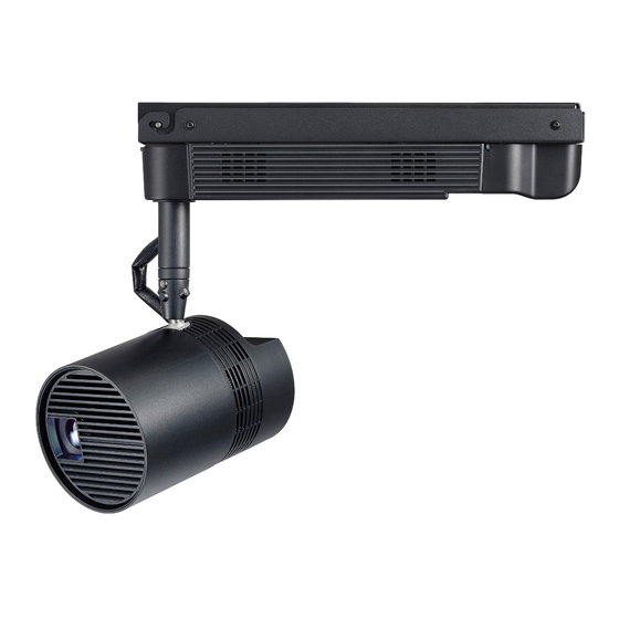
* Above illustration is shown in combination of this product and optional projector.
Thank you for purchasing this Panasonic product.
■ To customers
This manual is intended for use by installation personnel. Be sure to employ certified personnel to perform the installation.
After installation, have the installation personnel return this manual to you, and save it for future use.
When moving or removing the projector, give this manual to the certified personnel and have them perform the procedure.
■ To installation personnel
Read the instructions thoroughly and then perform the instaration correctly and safely.
Be sure to read through the section entitled "Read this first!" ( pages 2 to 3) before proceeding with the installation.
After installation, return this manual to the customer.
Installation Instructions
ET-JPC100BU
Model No.
ET-JPC100WU
Ceiling Kit
ENGLISH
FRANÇAIS
ESPAÑOL
ENGLISH
DPQX1104ZA
Advertisement
Table of Contents

Related Manuals for Panasonic et-jpc100bu

Summary of Contents for Panasonic et-jpc100bu
- Page 1 ESPAÑOL * Above illustration is shown in combination of this product and optional projector. Thank you for purchasing this Panasonic product. ■ To customers This manual is intended for use by installation personnel. Be sure to employ certified personnel to perform the installation.
-
Page 2: Read This Fi Rst
Read this fi rst! WARNING: THIS APPARATUS MUST BE EARTHED. Proper grounding is required to ensure personal safety. WARNING Ask a qualifi ed technician or your dealer to perform the installation work. Inadequate installation may result in fi re, electric shocks, or falling of the projector. ... - Page 3 If the power cord itself is pulled, the lead will become damaged, and fi re, short-circuits or serious electric shocks will result. Panasonic disclaims all liability for any accidents or any damage caused by the installation of the ceiling mount bracket using methods that are not described in these Installation Instructions or methods that do not use the parts specifi...
-
Page 4: Table Of Contents
Contents Read this fi rst! ....................2 Installation precautions ..................5 Product composition ..................6 Before installation ..................... 7 Items to prepare ......................... 7 Names of parts ........................8 Installation orientation ......................9 Installation position ......................10 Installation ......................13 Main procedures ....................... -
Page 5: Installation Precautions
Installation precautions Install this product in a place that is strong enough to withstand the weight of both the projector and product. Install this product in a place where the intake and exhaust of the projector will not be blocked. ... -
Page 6: Product Composition
This projector mount bracket is mounted to the projector and then attached to the ceiling mount bracket. Adapter cover <1> This adapter cover hides the <AC IN> socket part of the (ET-JPC100BU: TKFE28802) projector. (ET-JPC100WU: TKFE28801) String (6103430249) <1> This is to prevent the adapter cover from dropping. -
Page 7: Before Installation
Before installation Items to prepare The items that you need to provide in advance in addition to the supplied parts to mount this product to a ceiling are as follows. This product is a bracket for mounting the projector (separately sold product) to a ceiling. ... -
Page 8: Names Of Parts
Before installation (continued) Names of parts Ceiling mount bracket Ceiling mount bolt hole Power connector Power cord Fixer cable tie attachment holes Terminal block Ceiling mount bolt hole Shaft Indoor wiring hole Projector mount bracket Power cord hole Hook parts 8 - ENGLISH... -
Page 9: Installation Orientation
Before installation (continued) Installation orientation Mount this product in the specifi ed orientation to a fl at ceiling or a ceiling with a slope of up to 45°. Mounting this product to an inappropriate surface such as to a wall or fl oor or mounting it to a ceiling with a steep slope or in the wrong orientation may cause a fall or drop accident. -
Page 10: Installation Position
Before installation (continued) ■ When mounting this product to the ceiling, mount it so that the shaft side of the ceiling mount bracket is higher than the power supply cord side. Shaft side Ceiling Power cord side Can be installed Cannot be installed Note ... - Page 11 Before installation (continued) Projection distance (when aspect ratio 16:10) The following shows the dimensional relationship between the projector and projection surface. The dimensions included in the following table have a slight error. Also, when keystone correction is performed on the projector side, correction is made so that the projected image size becomes smaller than the specifi...
- Page 12 Before installation (continued) <Ceiling hole positions dimensions> Unit: mm Wood screw installation position (×4) Projector pole center position Wood screw installation Hole for indoor wiring position (×4) M10 bolt hole 77.5 (3-1/16") M10 bolt hole (for ceiling mount bolt) (for ceiling mount bolt) 87.5 (3-7/16") 360 (14-3/16") 370 (14-9/16")
-
Page 13: Installation
Installation Main procedures The main procedures for using this product to install a projector (separately sold product) on a ceiling are as fol- lows. Before performing the work, be sure to shut off the power supply to the room by, for example, turning off the wir- ing circuit breaker. - Page 14 Installation (continued) When the ceiling mount bolt installation location is concrete Anchor nut or Anchor nut or curled plug curled plug Concrete Hexagonal nut Hexagonal nut Flat washer Flat washer Ceiling mount bolt Ceiling mount bolt Spring washer Spring washer Hexagonal nut Hexagonal nut...
- Page 15 Installation (continued) When the ceiling mount bolt installation location is a wooden beam Spring washer Spring washer Flat washer Hexagonal nut Hexagonal nut Flat washer Beam Ceiling mount bolt Ceiling mount bolt Hexagonal nut Flat washer Flat washer Hole for indoor wiring Hexagonal nut Ceiling board...
- Page 16 Installation (continued) When mounting to a reinforced ceiling with wood screws Hole for indoor wiring Reinforcement Ceiling board Terminal block Indoor wiring hole (bracket side) Wood screw Wood screw Ceiling mount bracket Wood screw Wood screw installation holes installation holes Indoor wiring hole 1) Drill mounting holes in reference to “Mounting hole dimensions”...
-
Page 17: Connecting The Indoor Wiring For The Power Supply
Installation (continued) Connecting the indoor wiring for the power supply This section describes connecting the indoor wiring for the power supply to the terminal block of the ceiling mount bracket. Single copper wires with an AWG12 to AWG14 are supported for the wiring. 1) Strip the coating off the wires. -
Page 18: Changing The Orientation Of The Main Unit Of The Projector
Installation (continued) Changing the orientation of the main unit of the projector. This section describes changing the orientation of the main unit of the projector to make the mounting work of the projector mount bracket easier to do. 1) Place the projector on a cloth or the like that Rotating fi... -
Page 19: Mounting The Projector Mount Bracket To The Projector
Installation (continued) Mounting the projector mount bracket to the projector This section describes mounting the projector mount bracket to the projector. Power supply unit 1) Place the projector on the work bench. Place the power supply unit of the projector on a work bench that has a soft cloth or the like laid on it. - Page 20 Installation (continued) 4) Rotate the projector mount bracket. Orient the projector mount bracket to match the orientation of the power supply unit of the projector. 5) Slide the projector mount bracket. Slide the projector mount bracket so that it attaches to the <AC IN>...
-
Page 21: Mounting The Projector To The Ceiling Mount Bracket
Installation (continued) 6) Secure the projector mount bracket with the screws, captive washers. Firmly secure the projector mount bracket with the four supplied screws, captive washers (M4 x 8). Mounting the projector to the ceiling mount bracket Attach the projector that is mounted to the projector mount bracket to the ceiling mount bracket that is mounted to the ceiling. - Page 22 Installation (continued) 2) Lift up the projector mount bracket. Hook part While passing the power cord through the power cord hole of the projector mount bracket Power cord (i), lift up the projector mount bracket using the hook parts as the pivot point (ii). ⅱ...
-
Page 23: Connecting The Power Cord To The Projector
Installation (continued) Connecting the power cord to the projector This section describes connecting the power cord installed in the ceiling mount bracket to the projector. To prevent disconnection of the power cord, fi rmly insert the connector all the way into the <AC IN> sock- et of the projector and then secure it in place. - Page 24 Installation (continued) 4) Close the connector secure lock. While the string is hooked onto the cover, push until the tabs of the connector secure lock click into place. Take care not to trap the string with a tab. The string is for preventing the adapter cover from becoming detached and dropping Make sure that it is hooked onto the connector secure lock.
-
Page 25: Adjusting The Projection Position
Installation (continued) Adjusting the projection position This section describes determining the projection position by adjusting the orientation of the main unit of the pro- jector. 1) Loosen the fi xing screw of the projector. Loosen the rotating fi xing screw and the two ball joint fi... - Page 26 Installation (continued) When you loosen the two ball joint fi xing screws, the ball joint can move freely. This allows you to rotate the main unit 360° or tilt the main unit 90° with the ball joint moving part. Ball joint movement range: Approx.
-
Page 27: Specifi Cations
Depth: 439.5 mm (17-5/16ʺ) Weight 1.7 kg (3.75 lbs.) ET-JPC100BU: Black (for use in combination with PT-JW130FBU) Outer color ET-JPC100WU: White (for use in combination with PT-JW130FWU) *1: The dimensions are when just the product is in an assembled state and exclude the protrusions, power cord, and adapter cover. - Page 28 These symbols are only valid in the European Union. If you wish to discard this product, please contact your local authorities or dealer and ask for the correct method of disposal. Web Site : http://panasonic.net/avc/projector/ TI0716AM0 -PS © Panasonic Corporation 2016...