Table of Contents
Advertisement
Quick Links
TABLE OF CONTENTS
1 Safety Precautions----------------------------------------------- 3
2 Specifications ----------------------------------------------------- 5
2.1. CS-C18GKD CU-C18GKD ------------------------------ 5
2.2. CS-C24GKD CU-C24GKD ------------------------------ 7
3 Features ------------------------------------------------------------- 9
4 Location of Controls and Components ------------------10
4.1. Product Overview-----------------------------------------10
5 Dimensions--------------------------------------------------------11
CS-C18GKD CU-C18GKD
CS-C24GKD CU-C24GKD
PAGE
5.1. Indoor Unit & Remote Control ------------------------ 11
5.2. Outdoor Unit----------------------------------------------- 12
6 Refrigeration Cycle Diagram -------------------------------- 13
7 Block Diagram --------------------------------------------------- 14
8 Wiring Connection Diagram--------------------------------- 15
8.1. CS-C18GK CU-C18GK--------------------------------- 15
8.2. CS-C24GK CU-C24GK--------------------------------- 16
9 Electronic Circuit Diagram----------------------------------- 17
© 2006 Panasonic HA Air-Conditioning (M) Sdn.
Bhd. (11969-T). All rights reserved. Unauthorized
copying and distribution is a violation of law.
Order No. MAC0612072C8
Air Conditioner
PAGE
Advertisement
Table of Contents

Related Manuals for Panasonic CS-C18GKD


Summary of Contents for Panasonic CS-C18GKD
-
Page 1: Table Of Contents
4 Location of Controls and Components ------------------10 8.1. CS-C18GK CU-C18GK--------------------------------- 15 4.1. Product Overview-----------------------------------------10 8.2. CS-C24GK CU-C24GK--------------------------------- 16 5 Dimensions--------------------------------------------------------11 9 Electronic Circuit Diagram----------------------------------- 17 © 2006 Panasonic HA Air-Conditioning (M) Sdn. Bhd. (11969-T). All rights reserved. Unauthorized copying and distribution is a violation of law. - Page 2 10 Printed Circuit Board ------------------------------------------ 18 10.1. Indoor Unit ------------------------------------------------- 18 10.2. Indicator ---------------------------------------------------- 20 11 Installation Instruction ---------------------------------------- 21 11.1. Indoor Unit ------------------------------------------------- 22 11.2. Outdoor Unit ----------------------------------------------- 24 12 Operation and Control----------------------------------------- 27 12.1. Cooling Operation---------------------------------------- 27 12.2. Soft Dry Operation --------------------------------------- 28 12.3.
-
Page 3: Safety Precautions
1 Safety Precautions • Read the following “SAFETY PRECAUTIONS” carefully before perform any servicing. • Electrical work must be installed or serviced by a licensed electrician. Be sure to use the correct rating of the power plug and main circuit for the model installed. •... - Page 4 4. Pb free solder has a higher melting point than standard solder; typically the melting point is 50 - 70°F (30 - 40°C) higher. Please use a high temperature solder iron. In case of the soldering iron with temperature control, please set it to 700 ± 20°F (370 ± 10°C). Pb free solder will tend to splash when heated too high (about 1100°F / 600°C).
-
Page 5: Specifications
2 Specifications 2.1. CS-C18GKD CU-C18GKD Item Unit Indoor unit Outdoor unit Performance Test Condition NEW JIS Capacity 5.30 - 5.30 BTU/h 18100 - 18100 *kJ/h — 3.08 - 3.01 BTU/hW 10.52 - 10.28 Noise Level dB (A) High: 42 Low: 37... - Page 6 Item Unit Power Source (Phase, Voltage, Cycle) ø Single Single Input power 1.72k 1.76k Starting Current Running Current Cooling Power Factor Cooling Power factor means total figure of compressor, indoor fan motor and outdoor fan motor. Power Cord Number of core 3 (1.5mm) Length m (ft)
-
Page 7: Cs-C24Gkd Cu-C24Gkd
2.2. CS-C24GKD CU-C24GKD Item Unit Indoor unit Outdoor unit Performance Test Condition NEW JIS Capacity 7.03 - 7.03 BTU/h 24000 - 24000 *kJ/h — 2.99 - 2.92 BTU/hW 10.21 - 9.96 Noise Level dB (A) High: 46 Low: 40 High: 53 / 54 Power level dB —... - Page 8 Item Unit Power Source (Phase, Voltage, Cycle) ø Single Single Input power 2.35 2.41 Starting Current Running Current Cooling 11.5 11.6 Power Factor Cooling Power factor means total figure of compressor, indoor fan motor and outdoor fan motor. Power Cord Number of core 3 (2.5mm) Length...
-
Page 9: Features
3 Features • High Efficiency • Compact Design • Wider range of horizontal discharge air • Air Filter with function to reduce dust and smoke • Automatic air swing by Remote Control for vertical and horizontal airflow • Long Installation Piping - CS/CU-C18GK, CS/CU-C24GK, long piping up to 25 meter •... -
Page 10: Location Of Controls And Components
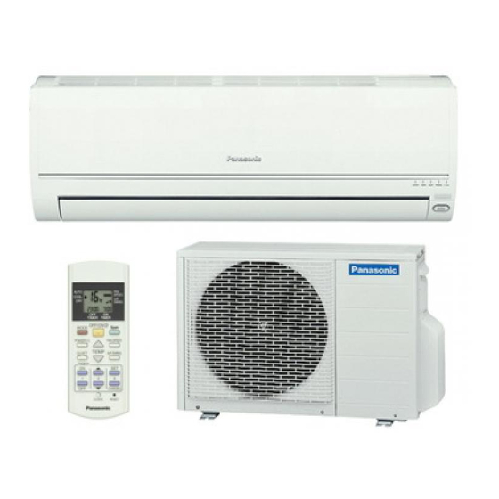
4 Location of Controls and Components 4.1. Product Overview 4.1.1. Indoor Unit 4.1.2. Outdoor Unit 4.1.3. Remote Control... -
Page 11: Dimensions
5 Dimensions 5.1. Indoor Unit & Remote Control 5.1.1. CS-C18GK CS-C24GK... -
Page 12: Outdoor Unit
5.2. Outdoor Unit 5.2.1. CU-C18GK 5.2.2. CU-C24GK... -
Page 13: Refrigeration Cycle Diagram
6 Refrigeration Cycle Diagram... -
Page 14: Block Diagram
7 Block Diagram... -
Page 15: Wiring Connection Diagram
8 Wiring Connection Diagram 8.1. CS-C18GK CU-C18GK Resistance of Outdoor Fan Motor Windings Resistance of Compressor Windings MODEL CU-C18GK MODEL CU-C18GK CONNECTION CWA951264J CONNECTION 2KS314D5AA02 217 Ω 1.487 Ω BLUE-GRAY C - R 217 Ω 3.530 Ω GRAY-RED C - S Note: Resistance at 25°C of ambient temperature. -
Page 16: Cs-C24Gk Cu-C24Gk
8.2. CS-C24GK CU-C24GK Resistance of Outdoor Fan Motor Windings Resistance of Compressor Windings MODEL CU-C24GK MODEL CU-C24GK CONNECTION CWA951352J CONNECTION 2JS438D3GA02 99.6 Ω 0.830 Ω BLUE-YELLOW C - R 126.8 Ω 2.257 Ω YELLOW-RED C - S 158.7 Ω YELLOW-ORANGE Note: Resistance at 20°C of ambient temperature. -
Page 17: Electronic Circuit Diagram
9 Electronic Circuit Diagram... -
Page 18: Printed Circuit Board
10 Printed Circuit Board 10.1. Indoor Unit TOP VIEW... - Page 19 BOTTOM VIEW...
-
Page 20: Indicator
10.2. Indicator TOP VIEW BOTTOM VIEW... -
Page 21: Installation Instruction
11 Installation Instruction Indoor/Outdoor Unit Installation Diagram SELECT THE BEST LOCATION INDOOR UNIT • There should not be any heat source or steam near the unit. • There should not be any obstacles blocking the air circulation. • A place where air circulation in the room is good. •... -
Page 22: Indoor Unit
11.1. Indoor Unit 11.1.1. HOW TO FIX INSTALLATION PLATE 11.1.2. TO DRILL A HOLE IN THE WALL The mounting wall is strong and solid enough to prevent it from INSTALL SLEEVE the vibration. PIPING 1. Insert the piping sleeve to the hole. 2. - Page 23 3. For the embedded piping (This can be used for left rear piping and left bottom piping also.)
-
Page 24: Outdoor Unit
11.1.4. CONNECT THE CABLE TO THE INDOOR UNIT 1. The inside and outside connecting cable can be connected without removing the front grille. 2. Connecting cable between indoor unit and outdoor unit shall be approved polychloroprene sheathed 3 × 2.5 mm flexible cord, type designation 245 IEC 57 or heavier cord. - Page 25 11.2.2. CONNECTING THE PIPING Connecting The Piping To Indoor Unit Please make flare after inserting flare nut (locate at joint portion of tube assembly) onto the copper pipe. (In case of using long piping) Connect the piping • Align the center of piping and sufficiently tighten the flare nut with fingers.
- Page 26 4. Close the Low side valve of the charging set and turn off the vacuum pump. Make sure that the needle in the gauge does not move after approximately five minutes. Note: BE SURE TO FOLLOW THIS PROCEDURE IN ORDER TO AVOID REFRIGERANT GAS LEAKAGE. 5.
-
Page 27: Operation And Control
12 Operation and Control 12.1. Cooling Operation • Cooling operation can be set using remote control. • This operation is applied to cool down the room temperature reaches the setting temperature set on the remote control. • The remote control setting temperature, which takes the reading of intake air temperature sensor, can be adjusted from 16°C to 30°C. -
Page 28: Soft Dry Operation
12.2. Soft Dry Operation • Soft Dry operation can be set using remote control. • Soft Dry operation is applied to dehumidify and to perform a gentle cooling to the room. • This operation starts when the intake air temperature sensor reaches the setting temperature on the remote control. •... -
Page 29: Automatic Operation
12.3. Automatic Operation • Automatic operation can be set using remote control. • This operation starts to operate with indoor fan at SLo speed for 25 seconds to judge the intake air temperature. • After judged the temperature, the operation mode is determined by referring to the below standard. •... -
Page 30: Operation Control
12.4. Operation Control 12.4.1. Restart Control (Time Delay Safety Control) • When the thermo-off temperature (temperature which compressor stops to operate) is reached during:- - Cooling operation - the compressor stops for 3 minutes (minimum) before resume operation. - Soft Dry operation - the compressor stops for 6 minutes (minimum) before resume operation. •... - Page 31 12.4.5. Compressor Reverse Rotation Protection Control • If the compressor is operating continuously for 5 minutes or longer and the temperature difference between intake air and indoor heat exchanger is 2.5°C or less for continuous 2 minutes, compressor will stop and restart automatically. •...
- Page 32 2. Norrowing Vertical Airflow Direction – During dew prevention control, Airflow Direction Auto-control angle change from 10° - 38° to 10° - 27° under Cooling and Soft Dry operation mode. – During dew prevention control, Airflow Direction Manual control angle change from 10°, 14°, 18°, 22°, 27° to 10°, 13°, 16°, 19°, 22°...
-
Page 33: Indoor Fan Speed Control
12.5. Indoor Fan Speed Control • Indoor Fan Speed can be set using remote control. 12.5.1. Fan Speed Rotation Chart COOL/DRY CS-C24GKD CS-C18GKD S Hi 1590 1460 1500 1400 1390 1250 H Lo 1330 1220 C Lo 1240 1150 1100... -
Page 34: Outdoor Fan Speed Control
• Auto Fan Speed during Soft Dry operation: 1. Indoor fan will rotate alternately between off and Lo-. 2. At the beginning of each compressor start operation, indoor fan will increase fan speed gradually for deodorizing purpose. 3. When compressor at turn off condition for 6 minutes, indoor fan will start fan speed at Lo- to circulate the air in the room. This is to obtain the actual reading of intake air temperature. -
Page 35: Vertical Airflow Direction Control
12.7. Vertical Airflow Direction Control 12.7.1. Auto Control • When the vertical airflow direction is set to Auto using the remote control, the louver swings up and down as shown in the diagram. • When stopped with remote control, the discharge vent is reset, and stop at the closing position. •... -
Page 36: Powerful Operation
12.8.2. Manual Control • When the horizontal airflow direction is set to Manual using the remote control, the automatic airflow is released and the airflow direction vane move left and right in the range shown in the diagram. The louver can be adjusted by pressing the button to the desired vane position. •... -
Page 37: Quiet Operation
12.10. Quiet Operation (For Cooling Operation or cooling region of Soft Dry Operation) • The Quiet operation is to provide quiet/cooling operation condition compare to normal operation. • Once the Quiet Mode is set at the remote control, the Quiet Mode LED illuminated. The sound level will reduce around 2 dB (A) for Lo fan speed or 3 dB(A) for Hi/Me fan speed against the present operation sound level. -
Page 38: Random Auto Restart Control
12.11.2. OFF Timer • When the OFF Timer is set by using the remote control, the unit will stop operate according to the desired setting. Notes 1. By pressing ON/OFF operation button, the ON Timer or OFF Timer setting will not be cancelled. 2. -
Page 39: Patrol Operation
12.14. Patrol Operation 1. Purpose To monitor air dirtiness level by using gas sensor and activates e-ion operation whenever air is dirty. 2. Control Condition a. Patrol operation start condition • When the unit operation is started with “OFF/ON” button. •... - Page 40 3. Control Content a. Gas Sensor Control • First 2 minutes from Patrol function activates is stabilization time, during stabilization time, no air dirtiness level is monitored. The Air Dirtiness level is set to level 2. • After that, gas sensor starts to record the resistance value at fixed interval. Higher resistance value indicates cleaner air. •...
- Page 41 c. Indoor Fan Control • During any operation mode combines with Patrol operation, fan speed follows respective operation mode. • During Patrol individual operation if e-ion starts, only Auto Fan Speed and no Powerful operation is allowed. Even if “Fan Speed”...
-
Page 42: E-Ion Operation
12.15. e-ion Operation 1. Purpose This operation provides clean air by producing negative ions to attract dust captured at the positively charged e-ion filters. 2. Control Condition a. e-ion operation start condition • During unit running at any operation mode, if “e-ion” button is pressed, combination operation (operation mode + e-ion operation) starts. - Page 43 3. Control Content a. Indoor fan control • During any operation mode combines with e-ion operation, fan speed follows respective operation mode. • During e-ion individual operation - only Auto Fan Speed and no Powerful operation is allowed. Even if Fan Speed button is pressed, no signal is sent to air conditioner, and no change on LCD display.
- Page 44 g. Error Detection Control When e-ion indicator blink, it indicates error listed below: a. e-ion AIR PURIFYING SYSTEM main connector to PCB is open: Judgment Method • During e-ion operation (include during Patrol operation), e-ion AIR PURIFYING SYSTEM main connector to PCB is opened.
-
Page 45: Servicing Mode
13 Servicing Mode 13.1. Auto OFF/ON Button 1. AUTO OPERATION MODE The Auto operation will be activated immediately once the Auto OFF/ON button is pressed. This operation can be use to operate air conditioner with limited function if remote control is misplaced or malfunction. 2. -
Page 46: Remote Control Button
13.3. Remote Control Button 13.3.1. SET BUTTON • To check current remote control transmission code. - Press for more than 10 seconds. • To change the air quality sensor sensitivity: - Press and release with pointer. - Press the Timer Decrement button to select sensitivity: 1. -
Page 47: Troubleshooting Guide
14 Troubleshooting Guide 14.1. Refrigeration cycle system In order to diagnose malfunctions, make sure that there are no electrical problems before inspecting the refrigeration cycle. Such problems include insufficient insulation, problem with the power source, malfunction of a compressor and a fan. The normal outlet air temperature and pressure of the refrigeration cycle depends on various conditions, the standard values for them are shown in the table to the right. - Page 48 14.1.1. Relationship between the condition of the air conditioner and pressure and electric current Cooling Mode Condition of the air conditioner Low Pressure High Pressure Electric current during operation Insufficient refrigerant (gas leakage) Clogged capillary tube or Strainer Short circuit in the indoor unit Heat radiation deficiency of the outdoor unit Inefficient compression...
-
Page 49: Disassembly And Assembly Instructions
15 Disassembly and Assembly Instructions WARNING • Cautions! When handling electronic controller, be careful of electrostatic discharge. • Be sure to return the wiring to its original position. • There are many high voltage components within the heat sink cover so never touch the interior during operation. Wait at least two minutes after power has been turned off. -
Page 52: Indoor Fan Motor And Cross Flow Fan Removal Procedures
15.2. Indoor Fan Motor and Cross Flow Fan Removal Procedures... -
Page 54: Technical Data
16 Technical Data 16.1. Thermostat Characteristics Cooling Soft Dry... -
Page 55: Operation Characteristics
16.2. Operation Characteristics 16.2.1. CS-C18GK CU-C18GK... - Page 57 16.2.2. CS-C24GK CU-C24GK...