
Related Manuals for Electrolux EHT8


Summary of Contents for Electrolux EHT8
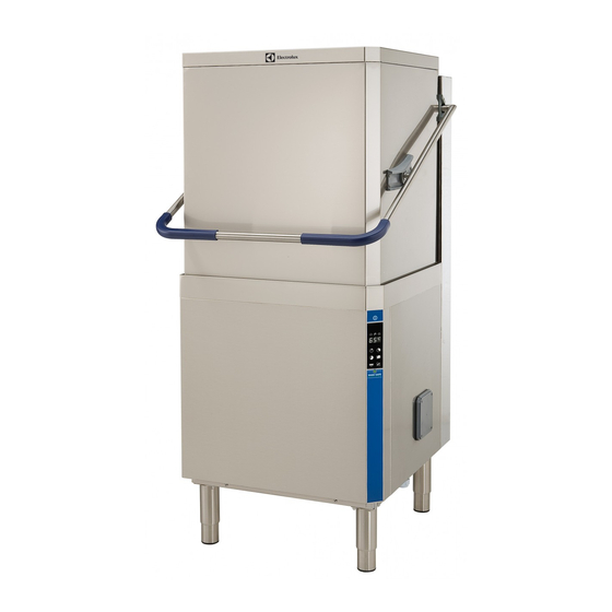
- Page 1 Hood Dishwasher EHT8/HHT8/KHT8/NHT8/XHT8/VHT7/ ZHT8/AHT8I/EHT8I/HHT8I/XHT8I/VHT7I/ ZHT8I/ZHT8TI/EHT8TI Installation and operating manual * 59566NR01- 2019.10 *Original instructions...
- Page 2 Installation diagram Manual hood type (single skin) without drain pump and without Energy Saving Device (ESD)
- Page 3 Installation diagram Manual hood type (single skin) without drain pump and with Energy Saving Device (ESD)
- Page 4 Installation diagram Manual hood type (single skin) with drain pump and without Energy Saving Device (ESD)
- Page 5 Installation diagram Manual hood type (single skin) with drain pump and with Energy Saving Device (ESD)
- Page 6 Installation diagram Manual hood type (double skin) with drain pump and without Energy Saving Device (ESD)
- Page 7 Installation diagram Manual hood type (double skin) with drain pump and with Energy Saving Device (ESD)
- Page 8 Installation diagram Automatic hood type with drain pump and without Energy Saving Device (ESD)
- Page 9 Installation diagram Automatic hood type with drain pump and with En- ergy Saving Device (ESD)
- Page 10 CWI = Cold water Inlet pipe ⌀=3/4″ G EI = Electrical Inlet WI = Water Inlet pipe ⌀=3/4″ G EQ = Equipotential screw D = Drain pipe internal ⌀=40 mm(ʌ) - 20 mm(*) XD = Inlet pipe for detergents (ʌ) Only for model with free-fall drainage XR = Inlet pipe for rinse-aid (*) Only for model with drain pump XI = Inlet pipe for delime...
- Page 11 Foreword The installation, use and maintenance manual (hereinafter Manual) provides the user with information necessary for correct and safe use of the machine (or “appliance“). The following must not be considered a long and exacting list of warnings, but rather a set of instructions suitable for improving machine performance in every respect and, above all, preventing injury to persons and animals and damage to property due to im- proper operating procedures.
-
Page 12: Table Of Contents
Contents A SAFETY INSTRUCTIONS ........................14 General safety ........................... 14 B GENERAL INFORMATION ........................14 Introduction ..........................14 General safety instructions ......................14 Additional indications........................14 Definitions..........................14 Machine and Manufacturer‘s identification data ................. 15 Appliance identification ........................ 15 B.6.1 How to identify the technical data..................15 B.6.2 How to interpret the factory description .................. - Page 13 End of service and daily internal cleaning..................35 K.2.1 Cleaning the nozzle jets...................... 36 Maintenance ..........................36 K.3.1 Repair and extraordinary maintenance .................. 36 K.3.2 Parts and accessories ......................36 K.3.3 Prolonged period of inactivity ....................36 Boiler drainage........................... 36 Preventive maintenance.......................
-
Page 14: Asafety Instructions
The following symbols are Manufacturer Electrolux Professional SpA or any other used in the manual to indicate and identify service centre authorised by Electrolux Professional SpA. the various types of hazards:... -
Page 15: Machine And Manufacturer's Identification Data
Type ref. 6.9 kW Electrolux Professional spa - Viale Treviso, 15 Electrolux Professional spa - Viale Treviso, 15 - 33170 Pordenone (Italy) The dataplate gives the product identification and technical data; listed below is the meaning of the various information given on it. -
Page 16: Copyright
(the fitting and use of non-original Electrolux Professional spa - Viale Treviso, 15 - 33170 Pordenone (Italy) spare parts and accessories can negatively affect machine operation and invalidates the warranty);... -
Page 17: Ctechnical Data
PPE). Failure to use the personal protection equipment by operators, specialized personnel or users can involve exposure to chemical risk and cause possible damage to health (depending on the model). TECHNICAL DATA Main technical characteristics Model NHT8/EHT8/ ZHT8I/AHT8I/ KHT8/HHT8/ EHT8I/NHT8I/ EHT8M/... -
Page 18: Characteristics Of Power Supply
Model NHT8/EHT8/ ZHT8I/AHT8I/ KHT8/HHT8/ EHT8I/NHT8I/ EHT8M/ EHT8M6/ EHT8TIL/ XHT8/ZHT8/ HHT8I/XHT8I/ EHT8IUSPH5 EHT8IUSPH6 ZHT8TIL VHT7/ VHT7I/ Cycle duration in “High 45-84-150 45-84-150 Productivity“ mode sec. 50-84-150 50-84-150 45-84-150 45-84-150 45-84-150 (VHT7G) (VHT7IG) Cycle duration in “NSF/ sec. 57-84-150 57-84-150 57-84-150 57-84-150 57-84-150 ANSI3“... -
Page 19: Dtransport, Handling And Storage
WARNING For protection against indirect contacts (depending on the type of supply provided for and connection of earths to the equipotential protection circuit) refer to point 6.3.3 of EN 60204-1 (IEC 60204-1) with the use of protection devices that ensure automatic cut-off of the supply in case of isolation fault in the TN or TT systems or, for IT systems, the use of isolation controllers or differential current protection devices to activate automatic power disconnec- tion (an isolation controller must be provided for indicating a possible first... -
Page 20: Storage
CAUTION Storage Do not make modifications to the parts The machine and/or its parts must be stored and protected supplied with the appliance. Any missing from damp, in a non-aggressive place, free of vibrations and or faulty parts must be replaced with with room temperatures between -10℃... -
Page 21: Extraction Hood
Disposal of packing • Carefully remove the protective film from the outer panels without tearing it, to avoid leaving traces of glue. The packing must be disposed of in compliance with the current regulations in the country where the appliance is used. All the packing materials are environmentally friendly. -
Page 22: Plumbing Circuits
Plumbing circuits Hood dishwasher with drain pump and Energy Saving Device (ESD) Hood dishwasher without drain pump • M3 = Rinse pump LEGEND • AG = Air Gap • WI = Water inlet YV1 = Filling solenoid • D = Drain valve •... -
Page 23: Electrical Connections
E.10 Electrical connections Power supply 220 - 230V 3 Open the power supply terminal board and insert the jumpers WARNING provided as follows: one jumper between terminals 1 and 2, Work on the electrical systems one between terminals 3 and 4 and another between terminals 5 and 6. -
Page 24: Haccp" Arrangement
• If the water level in the tank is too high, the drain pump (if present) automatically activates to empty out the excess water. IMPORTANT The Manufacturer declines any liability if the accident-prevention regulations are not respected. E.12 “HACCP“ arrangement In some models the machine is not arranged for the “HACCP“... -
Page 25: Basic Controls
IMPORTANT The GUARANTEED RINSE SYSTEM (GRS) is incorporated in the ACTIVE/ WASH SAFE CONTROL models (see led “P”). The GRS is an automatic rinse time/temperature control system. Operation is as follows: • during the wash cycle the indicator light is OFF; •... -
Page 26: Detergent/Rinse Aid Dispensers And Prearrangements
flat filter “3“ and the basket filter “4“ are correctly fitted (see this value, access the parameter dIn (refer to H.2 Setting detail “A“). the dispensers). • In versions without supplementary Filtering System (FS) At each cycle, pump “R“ dispenses a detergent quantity in and without drain pump, make sure the filter “1“, the the tank providing a concentration of 2 g/l. -
Page 27: Hbefore First Use
To obtain excellence washing performance, use detergent, rinse aid and descaling agent sug- gested by Electrolux Professional. In the Electrolux Professional web site, open the “Accessories and Consumables“ web page and navigate into the dishwashing equipment tab to order most suitable detergents and accessories. -
Page 28: Note For External Dispenser
For example, to adjust the parameter dIn, proceed as 4. modify the parameter value and press the button “L“ to follows: store the set value; 1. access the programming mode; 5. to exit the programming mode, press the “Wash cycle 3“ button. -
Page 29: Igeneral Safety Rules
NOTE! CAUTION If changing to a different detergent/rinse- For electrical connections, see the wiring diagram. aid type (even one by the same manufac- turer), you must rinse the suction and pressure hoses with fresh water before connecting the new detergent/rinse-aid container. -
Page 30: Reasonably Foreseeable Improper Use
WARNING preserve these conditions, the areas around the machine must always be: Extraordinary machine mainte- • kept free of obstacles (e.g. ladders, tools, containers, boxes, nance operations must only be etc.); carried out by specialised per- • clean and dry; •... -
Page 31: Jnormal Machine Use
IMPORTANT Residual risk Description of hazardous In case of a significant anomaly (e.g. short circuits, situation wires coming out of the terminal block, motor Tipping of loads When handling the machine or the breakdowns, worn electrical cable sheathing, etc.) packing containing it, using unsuit- the operator must immediately deactivate the able lifting systems or accessories machine. -
Page 32: Operation
Table of times — Standard cycle time in “NSF/ANSI 3 • Cycle 3 compliant“ mode (factory default setting) For very dirty dishes: press button Wash cycle 3 (see table of times). With supply water temperature at 65°C [149°F]. • High Productivity or NSF/ANSI 3 compliant mode NOTE! Press and hold down (5 sec.) this button to switch the In models with Energy Saving Device (ESD) cycle... -
Page 33: Type Of Racks And Loading
Type of racks and loading Proceed as follows: • Insert the Delime hose present in the machine, identified by • YELLOW rack: for 18 plates with maximum diameter of 240 an appropriate label, in a container with at least 2l of wine vinegar 6% (2l is the minimum amount of vinegar needed for a correct Delime cycle). -
Page 34: Salt Container
Autonomy of the full salt container according to the • Pour approx. 2 kg of coarse salt [NaCl] in container “A“ (an change in inlet water hardness amount sufficient to fill the salt container up to the rim) using the special funnel supplied. Using cycle 2 The salt con- for 30 cycles/... -
Page 35: Kmachine Cleaning And Maintenance
MACHINE CLEANING AND MAINTENANCE Machine cleaning In versions with automatic hood and supplementary filtering system Cleaning must be carried out after every day of use. Use hot (see below picture, detail “A“) water, a neutral detergent/cleaner if necessary, and a soft brush or sponge. -
Page 36: Cleaning The Nozzle Jets
• Replace the filter and the overflow. intervention of an unauthorized technician by the Manufacturer and the original manufacturer warranty will be invalidated. K.3.2 Parts and accessories Use only original accessories and/or spare parts. Failure to use original accessories and/or spare parts will invalidate the original manufacturer warranty and may render the machine not compliant with the safety standard. -
Page 37: Waste Storage
WARNING general, the appliance must be taken to a specialised collection/ scrapping centre. Work on the electrical equipment must only be carried out by The symbol on the product indicates that this product should not be treated as domestic specialised personnel, with the waste, but must be correctly disposed of in power supply disconnected. -
Page 38: Alarms
Alarms NO WATER • Check that the tap is open. • Check that the water inlet filter is clean. • Check the minimum mains pressure. • Check that the overflow pipe is inserted (only for appliances without drain pump). INEFFICIENT DRAINAGE •... - Page 40 Electrolux Professional SPA Viale Treviso 15 33170 Pordenone www.electrolux-professional.com...