Table of Contents
Advertisement
Quick Links
Advertisement
Table of Contents

Summary of Contents for Panasonic VIEW 3
- Page 1 View Tag Product Family Specification & User Information Guide VT03-G3 VT03-G3C VT03-G3BKT VT04-G3 VT04-G3C VT04-G3BKT VT07-G3 VT07-G3BKT Attention Please read entire guide before product use IIoT Solutions Document: SPC-ENG-0000004-03 2021-02-02...
-
Page 2: Table Of Contents
Contents Introduction ..........................................3 Model Overview ........................................4 Model Delineation ......................................4 VIEW 3 ..........................................4 VIEW 3 Bracket ....................................... 4 VIEW 4 ..........................................4 VIEW 4 Bracket ....................................... 4 VIEW 7 ..........................................5 VIEW 7 Bracket ....................................... 5 View Tag Specifications ....................................6 Physical .......................................... - Page 3 Disposal of VIEW Tags and Batteries ............................... 16 For European Union and countries with recycling systems ...................... 16 Consideration for Battery Recycling ..............................16 Battery Removal ....................................... 16 VIEW 3 and VIEW 4 ....................................16 VIEW 7 ..........................................18 2.2.2021 Document:...
-
Page 4: Introduction
In this guide you will find an overview of the Panasonic View Tag family of products, as well as a starter guide on usage and installation. -
Page 5: Model Overview
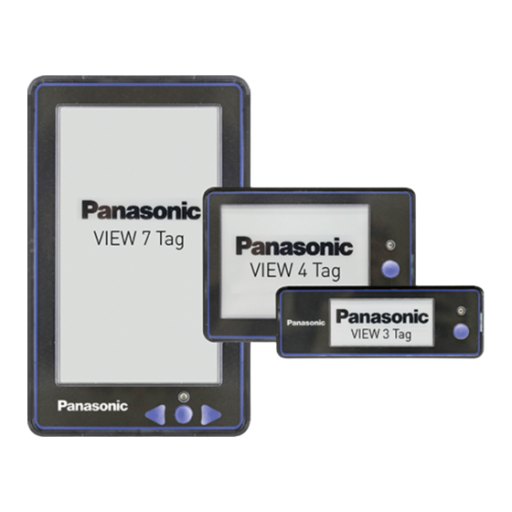
View Tag Product Family User Information Guide Model Overview Model Delineation VIEW 3 VIEW 3 Bracket Model Numbers(s) Model Numbers(s) VT03-G3 & VT03-G3C VT03-G3BKT Features ePaper Screen LED Light Button GPIO Port Figure 1 Figure 2 Figure 3 Figure 4... -
Page 6: View 7
View Tag Product Family User Information Guide VIEW 7 VIEW 7 Bracket Model Numbers(s) Model Numbers(s) VT07-G3 VT07-G3BKT Features ePaper Screen LED Light Buttons GPIO Port Figure 9 Figure 10 Figure 11 Figure 12 Tolerance Table (mm) 6 or Less +/- 0.3 Over 6 to 30 incl. -
Page 7: View Tag Specifications
(dBm) Modulation 2-GFSK Standard EPC Gen 2 Device Impinj MonzaX-2K VIEW 3 CM and VIEW 4 CM can operate in Gen2 compatible mode. Typical battery life under normal operating conditions; results will vary based on usage. 2.2.2021 Document: SPC-ENG-0000004-03 page... -
Page 8: Environment & Testing
Vibration MIL-STD-810G method 514.6 Cat. 24 Ingress Protection IP 50 Shock Survives 1-meter drop to concrete Button Actuation 5 million Bracket VIEW 3 Bracket VIEW 4 Bracket VIEW 7 Bracket Model number VT03-G3BKT VT04-G3BKT VT07-G3BKT Height 52.8 94.7 212.7 (mm) Width 170.0... -
Page 9: Using Panasonic View Tags
➢ Blink until Tag user presses button Button(s) The VIEW 3, VIEW 4, and VIEW 7 feature a single, round button for the user to interact with the tag, locally and system via designated communication channels. The following functions are supported: ➢... -
Page 10: Gpio Port
System/View Tag Interaction The Panasonic View Tag product line has embedded firmware allowing interaction with two separate administrative software packages. Utilizing the features in these applications, an administrator can interact with any specific tag or several at once depending on intent. Some of the most used features include: ➢... -
Page 11: Bracket Mounting
View Tag Product Family User Information Guide Bracket Mounting Mounting Position The features of the View Tag product line are designed with human interaction in mind. To maximize ease of use, and minimize fatigue and/or strain, the following mounting instructions are recommended for standard use: (shown in Figure 15) ➢... -
Page 12: Contact Us
Economic operators’ information in EU Manufacturer Panasonic Corporation 7-1-1, Morofuku, Daito-shi, Osaka 574-0044, Japan Importer Panasonic Electric Works Europe AG Caroline-Herschel-Straße 100, 85521 Ottobrunn, Germany Contact for CE Panasonic Marketing Europe GmbH Panasonic Testing Center Winsbergring 15, 22525 Hamburg, Germany 2.2.2021... -
Page 13: Safety& Legal Information
See: www.dtsc.ca.gov/hazardouswaste/perchlorate Safety Considerations Panasonic Corporation is consistently striving to improve quality and reliability. However, the fact remains that electrical components and devices generally cause failures at a given statistical probability. Furthermore, their durability varies with use environments or use conditions. -
Page 14: General Disclaimer
Scope In the event that Panasonic Corporation confirms any failures or defects of the Products by reasons solely attributable to Panasonic Corporation during the warranty period, Panasonic Corporation shall supply the replacements of the Products, parts or replace and/or repair the defective portion by free of charge at the location where the Products were purchased or delivered to your premises as soon as possible. -
Page 15: Information On The Batteries That Are Installed In This Product
View Tag Product Family User Information Guide Information on the batteries that are installed in this product The following separate collection symbol (crossed-out wheeled bin) is applied to the batteries that are installed in this product in accordance with the EU Battery Directive (2006/66/EC). -
Page 16: Regulatory Certifications
Safety IEC/EN 62368-1 Contact for CE: Panasonic Marketing Europe GmbH, Panasonic Testing Center, Winsbergring 15, 22525 Hamburg, Germany FCC Interface Statement This equipment has been tested and found to comply with the limits for a Class B digital device, pursuant to Part 15 of the FCC Rules. -
Page 17: Disposal Of View Tags And Batteries
Batteries should only be removed by qualified personnel wearing protective goggles and gloves. When removing the battery, care should be taken to avoid puncturing or otherwise damaging the battery body. VIEW 3 and VIEW 4 Structural Overview The upper and lower cases are The battery is glued to the back of the welded at the dotted line. - Page 18 View Tag Product Family User Information Guide Step 2 Remove the circuit board FOR VIEW 4 ONLY: The circuit board is held in place with heat-staked posts at 7 locations. Scrape or snip these off to release the board. Step 3 Disconnect the battery terminals CAUTION: •...
-
Page 19: View 7
View Tag Product Family User Information Guide VIEW 7 Step 1 Remove the outer window Outer Window is adhered to plastic case with adhesive. Pry up at edges of window using a flat blade. Step 2 Remove the screws Remove the 6 screws as shown using a T8 Torx screwdriver. Step 3 Remove the case top The case is held in place using snap features in the plastic part. - Page 20 View Tag Product Family User Information Guide Circuit board is not held in place with any features/adhesives and will come out easily. The Button and Light Pipe parts will come loose from circuit board. Step 5 Disconnect the battery terminals Cut the battery terminals where shown with diagonal pliers.