
Related Manuals for ABB ACQ810-04


Summary of Contents for ABB ACQ810-04
- Page 1 ABB industrial drives Hardware manual ACQ810-04 drive modules (1.1…45 kW, 1…60 hp)
-
Page 2: List Of Related Manuals
List of related manuals Drive hardware manuals and guides Code (English) ACQ810-04 drive modules (1.1…45 kW, 1…60 hp) 3AUA0000055160 hardware manual Drive firmware manuals and guides ACQ810-04 drive modules start-up guide 3AUA0000055159 ACQ810 standard pump control program 3AUA0000055144 firmware manual... - Page 3 Hardware manual ACQ810-04 drive modules (1.1…45 kW, 1…60 hp) Table of contents 1. Safety instructions 5. Mechanical installation 7. Electrical installation © 2009 ABB Oy. All Rights Reserved. 3AUA0000055160 Rev A EFFECTIVE: 2009-09-18...
-
Page 5: What This Chapter Contains
Safety instructions 5 Safety instructions What this chapter contains This chapter contains the safety instructions which you must follow when installing, operating and servicing the drive. If ignored, physical injury or death may follow, or damage may occur to the drive, the motor, or driven equipment. Read the safety instructions before you work on the unit. -
Page 6: Installation And Maintenance Work
• The drive is not field repairable. Never attempt to repair a malfunctioning drive; contact your local ABB representative or Authorized Service Center. • Make sure that dust from drilling does not enter the drive during the installation. -
Page 7: Start-Up And Operation
Safety instructions 7 • Ensure sufficient cooling. WARNING! The printed circuit boards contain components sensitive to electrostatic discharge. Wear a grounding wrist band when handling the boards. Do not touch the boards unnecessarily. Start-up and operation These warnings are intended for all who plan the operation of the drive, start up or operate the drive. - Page 8 8 Safety instructions...
-
Page 9: Table Of Contents
The ACQ810-04 ........ - Page 10 10 Table of contents Installation procedure ............36 Direct wall mounting .
- Page 11 Table of contents 11 Electrical installation ........... . . 61 Connecting the control cables .
- Page 12 12 Table of contents Patent protection in the US ..........93 11.
- Page 13 Providing feedback on ABB Drives manuals ........
- Page 14 14 Table of contents...
-
Page 15: About This Manual
The flowchart refers to chapters/sections in this manual and other manuals. Compatibility The manual is compatible with ACQ810-04 drive modules of frame sizes A to D. Intended audience This manual is intended for people who plan the installation, install, commission, use and service the drive. -
Page 16: Categorization According To The + Code
16 About this manual Categorization according to the + code The instructions, technical data and dimensional drawings which concern only certain optional selections are marked with + codes, e.g. +L500. The options included in the drive can be identified from the + codes visible on the type designation label of the drive. -
Page 17: Installation And Commissioning Flowchart
If the converter has been non-operational for more than one year, the converter DC Only intact units may be started up. link capacitors need to be reformed. Ask ABB for more information. Check the installation site. Mechanical installation: Before installation... - Page 18 18 About this manual Task If the drive is about to be connected to an IT Safety instructions: Installation and (ungrounded) system, disconnect the internal maintenance work (page 6) varistors and EMC filters. Also note that using an Electrical installation: Power cable EMC filter is not allowed in an IT (ungrounded) connection...
-
Page 19: Terms And Abbreviations
Optional PROFIBUS DP adapter for the ACQ810. Frame (size) Size of the drive module. This manual deals with ACQ810-04 frames A, B, C and D. To determine the frame size of a drive module, refer to the drive designation label attached to the drive,... - Page 20 20 About this manual...
-
Page 21: Operation Principle And Hardware Description
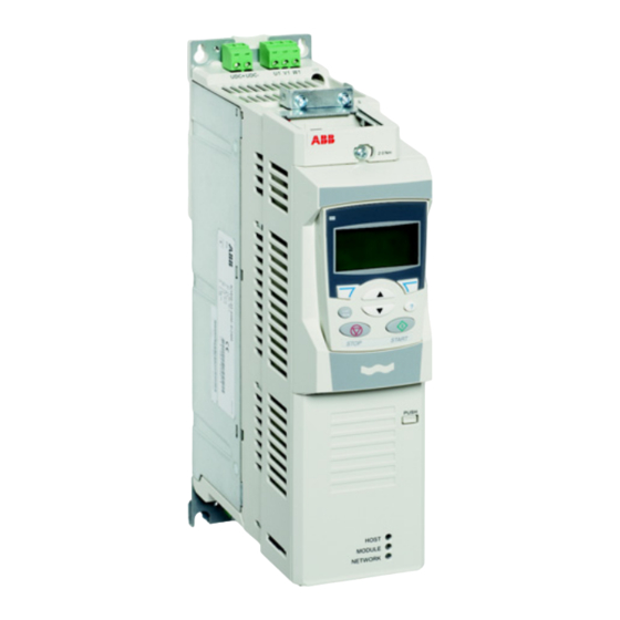
The ACQ810-04 The ACQ810-04 is an air-cooled IP20 drive module for controlling AC motors for water and waste water applications. It is to be installed into a cabinet by the customer. It is available in several frame sizes depending on output power. All frame sizes use... -
Page 22: Layout
22 Operation principle and hardware description Layout Drive module, frame size A JCU Control Unit with cover assembly removed DC connection AC supply External 24 V connection power input JCU Control Unit Relay outputs +24 V output Digital inputs Digital inputs/ outputs Slot 1 for optional Reference voltage... -
Page 23: Operation Principle
AC supply CHK-xx mains choke (see chapter Mains chokes on page 95) JFI-xx EMC filter (see chapter UDC+ UDC- V1 W1 EMC filters on page 99) ACQ810-04 Rectifier – Capacitor bank Inverter V2 W2 NOCHxxxx-xx du/dt filter (see chapter Motor output... -
Page 24: Power Connections And Control Interfaces
24 Operation principle and hardware description Power connections and control interfaces The diagram shows the power connections and control interfaces of the drive. Slot 1 Control unit (JCU) (I/O extension or fieldbus adapter) Slot 1 FIO-11 (Analog I/O extension) FIO-21 (Digital/Analog I/O Control panel or PC extension) FIO-31 (Digital I/O... -
Page 25: Type Designation
Type designation The type designation contains information on the specifications and configuration of the drive. The first digits from left express the basic configuration (e.g. ACQ810-04- 14A4-4). The optional selections are given thereafter, preceded by + signs (e.g. +L500). The main selections are described below. Not all selections are necessarily available for all types;... - Page 26 26 Operation principle and hardware description...
-
Page 27: Planning The Cabinet Assembly
Please note that the installation must, however, always be designed and made according to applicable local laws and regulations. ABB does not assume any liability whatsoever for any installation which breaches the local laws and/or other regulations. -
Page 28: Grounding Of Mounting Structures
Planning the fastening of the cabinet WARNING! Do not fasten the cabinet by electric welding. ABB does not assume any liability for damages caused by electric welding as the welding circuit may damage electronic circuits in the cabinet. -
Page 29: Main Dimensions And Free Space Requirements
Planning the cabinet assembly 29 Main dimensions and free space requirements The modules can be installed side by side. The dimensions of the drive modules as well as free space requirements are presented below. For more details, refer to chapter Dimension drawings. -
Page 30: Cooling And Degrees Of Protection
30 Planning the cabinet assembly Note: EMC filters of type JFI-x1 mounted directly above the drive module do not increase the free space requirements. (For EMC filters of type JFI-0x, see the dimension drawing of the filters on page 119.) 200 mm [7.9”] 300 mm [12”] The temperature of the cooling air entering the unit must not exceed the maximum... - Page 31 Planning the cabinet assembly 31 Air outlet Air inlet Arrange the cooling of the modules so that the requirements given in chapter Technical data are met: • cooling air flow Note: The values in Technical data apply to continuous nominal load. If the load is less than nominal, less cooling air is required.
-
Page 32: Preventing The Recirculation Of Hot Air
32 Planning the cabinet assembly Preventing the recirculation of hot air Cabinet (side view) AREA Main airflow out Air baffle plates COOL AREA Main airflow in Outside the cabinet Prevent hot air circulation outside the cabinet by leading the outcoming hot air away from the area where the inlet air to the cabinet is taken. -
Page 33: Mechanical Installation
Mechanical installation 33 Mechanical installation Contents of the package The drive is delivered in a cardboard box. To open, remove any banding and lift the top off the box. - Page 34 34 Mechanical installation The box contains: • ACQ810-04 drive module, with factory-installed options • three cable clamp plates (two for power cabling, one for control cabling) with screws • screw-type terminal blocks to be attached to the headers on the JCU Control Unit and the power unit •...
-
Page 35: Delivery Check And Drive Module Identification
Mechanical installation 35 Delivery check and drive module identification Check that there are no signs of damage. Before attempting installation and operation, check the information on the type designation label of the drive module to verify that the unit is of the correct type. The label is located on the left-hand side of the drive module. -
Page 36: Installation Procedure
36 Mechanical installation Installation procedure Direct wall mounting 1. Mark the locations for the four holes. The mounting points are shown in Dimension drawings. 2. Fix the screws or bolts to the marked locations. 3. Position the drive onto the screws on the wall. Note: Only lift the drive by its chassis. -
Page 37: Planning The Electrical Installation
Note: The installation must always be designed and made according to applicable local laws and regulations. ABB does not assume any liability whatsoever for any installation which breaches the local laws and/or other regulations. -
Page 38: Supply Disconnecting Device
38 Planning the electrical installation Supply disconnecting device Install a hand-operated input disconnecting device (disconnecting means) between the AC power source and the drive. The disconnecting device must be of a type that can be locked to the open position for installation and maintenance work. Europe If the drive is used in an application which must meet the European Union Machinery Directive according to standard EN 60204-1 Safety of Machinery, the disconnecting... -
Page 39: Motor Thermal Protection
The protective characteristics of circuit breakers depend on the supply voltage as well as the type and construction of the breakers. There are also limitations pertaining to the short-circuit capacity of the supply network. Your local ABB representative can help you in selecting the breaker type when the supply network characteristics are known. -
Page 40: Safe Torque Off
40 Planning the electrical installation Note: Pressing the stop key on the control panel of the drive does not generate an emergency stop of the motor or separate the drive from dangerous potential. Safe torque off The drive supports the Safe torque off function according to standards EN 61800-5-2:2007;... -
Page 41: Selecting The Power Cables
Planning the electrical installation 41 Note: If a running drive is stopped by using the Safe torque off function, the drive will cut off the motor supply voltage and the motor will coast to stop. Selecting the power cables General rules Dimension the supply (input power) and motor cables according to local regulations. -
Page 42: Alternative Power Cable Types
42 Planning the electrical installation Alternative power cable types Power cable types that can be used with the drive are represented below. Motor cable (also recommended for supply cabling) Symmetrical shielded cable: three phase Note: A separate PE conductor is required if conductors and a concentric or otherwise the conductivity of the cable shield is not symmetrically constructed PE conductor, and a... -
Page 43: Implementing A Bypass Connection
Planning the electrical installation 43 Implementing a bypass connection If bypassing is required, employ mechanically or electrically interlocked contactors between the motor and the drive and between the motor and the power line. Ensure with the interlocking that the contactors cannot be closed simultaneously. Follow this control sequence: 1. -
Page 44: Protecting The Relay Output Contacts And Attenuating Disturbances In Case Of Inductive Loads
44 Planning the electrical installation Protecting the relay output contacts and attenuating disturbances in case of inductive loads Inductive loads (relays, contactors, motors) cause voltage transients when switched off. The relay outputs on the drive are protected with varistors (250 V) against overvoltage peaks. -
Page 45: Selecting The Control Cables
Control panel cable The cable connecting the control panel to the drive must not exceed 3 metres in length. The cable type tested and approved by ABB is used in control panel option kits. Connection of a motor temperature sensor to the drive I/O... -
Page 46: Routing The Cables
46 Planning the electrical installation Routing the cables Route the motor cable away from other cable routes. Motor cables of several drives can be run in parallel installed next to each other. It is recommended that the motor cable, input power cable and control cables be installed on separate trays. Avoid long parallel runs of motor cables with other cables in order to decrease electromagnetic interference caused by the rapid changes in the drive output voltage. -
Page 47: Control Cable Ducts
Planning the electrical installation 47 Control cable ducts 24 V 230 V 24 V 230 V Not allowed unless the 24 V Lead 24 V and 230 V control cable is insulated for 230 V or cables in separate ducts inside insulated with an insulation the cabinet. - Page 48 48 Planning the electrical installation...
-
Page 49: Electrical Installation
Electrical installation 49 Electrical installation What this chapter contains This chapter describes the electrical installation procedure of the drive. WARNING! The work described in this chapter may only be carried out by a qualified electrician. Follow the Safety instructions on the first pages of this manual. - Page 50 50 Electrical installation...
-
Page 51: Checking The Insulation Of The Assembly
Protective Earth conductor using a measuring voltage of 500 V DC. The insulation resistance of an ABB motor must exceed 100 Mohm (reference value at 25 °C or 77 °F). For the insulation resistance of other motors, please consult the manufacturer’s instructions. -
Page 52: Power Cable Connection
(page 95). JFI-xx EMC filter (optional). See the chapter EMC filters (page 99). The UDC+/UDC– connectors can be used for common DC configurations. See page 59. ACQ810-04 UDC+ UDC– R– du/dt filter(s) (optional). See the chapter du/dt and common mode filtering (page 105). -
Page 53: Procedure
Electrical installation 53 Procedure Cabling drawings with tightening torques for each frame size are presented on pages to 58. 1. Frame sizes C and D only: Remove the two plastic connector covers at the top and bottom of the drive. Each cover is fastened with two screws. 2. - Page 54 54 Electrical installation 13. Ground the other end of the supply cable shield or PE conductor(s) at the distribution board. In case a mains choke and/or an EMC filter is installed, make sure the PE conductor is continuous from the distribution board to the drive. Grounding the motor cable shield at the motor end For minimum radio frequency interference, ground the cable shield 360 degrees at the lead-through of the motor terminal box...
- Page 55 Electrical installation 55 Installation of power cable clamp plates Two identical power cable clamp plates are included with the drive. The picture below depicts a frame size A drive; the installation is similar with other frame sizes. Note: Pay attention to supporting the cables adequately within the installation enclosure especially if not using the cable clamps.
- Page 56 56 Electrical installation Power cable connection – frame size A Supply cable Cable clamp on bare shield 1.5 N·m (13 lbf·in) Below cable clamp, cover bare shield with insulating tape 1.5 N·m (13 lbf·in) 0.5 … 0.6 N·m (4.4 … 5.3 lbf·in) 0.5 …...
- Page 57 Electrical installation 57 Power cable connection – frame size B Supply cable Cable clamp on bare shield 1.5 N·m (13 lbf·in) Below cable clamp, cover bare shield with insulating tape 1.5 N·m (13 lbf·in) 1.2 … 1.5 N·m (10.6 … 13.3 lbf·in) 1.5 N·m (13 lbf·in) Above cable clamp, cover bare shield with insulating tape...
- Page 58 58 Electrical installation Power cable connection – frame sizes C and D (connector covers removed) Supply cable Below cable clamp, cover Screw lug detail bare shield with insulating Cable clamp on bare tape shield 1.5 N·m (13 lbf·in) 15 N·m (11 lbf·ft) Frame C: 3 N·m (25 lbf·in) Frame D:...
-
Page 59: Dc Connection
Electrical installation 59 DC connection The UDC+ and UDC– terminals are intended for common DC configurations of a number of ACQ810 drives, allowing regenerative energy from one drive to be utilised by the other drives in motoring mode. One or more drives are connected to the AC supply depending on the power requirement. -
Page 60: Connecting A Pc
60 Electrical installation Each drive has an independent DC capacitor pre-charging circuit. UDC+ UDC- V1 W1 – Pre-charging circuit V2 W2 The ratings of the DC connection are given on page 84. Connecting a PC Connect the PC to connector X7 on the control unit (see page 22) or to the connector in the control panel holder. -
Page 61: Installation Of Optional Modules
Electrical installation 61 Installation of optional modules Optional modules such as fieldbus adapters and I/O extensions ordered using option codes (see Type designation on page 25) are pre-installed at the factory. Instructions for installing additional modules into the slots on the JCU Control Unit (see page for the available slots) are presented below. -
Page 62: Connecting The Control Cables
62 Electrical installation Connecting the control cables Control connections to the JCU Control Unit +24VI External power input 24 V DC, 1.6 A Relay output RO1 [Ready] 250 V AC / 30 V DC Relay output RO2 [Fault(-1)] 250 V AC / 30 V DC +24 V DC* +24VD Digital input ground... - Page 63 Electrical installation 63 Notes: [Default setting with ACQ810 Order of terminal headers and standard pump control program (Factory jumpers macro). See the Firmware manual for other macros.] *Total maximum current: 200 mA XPOW (2-pole) The wiring shown is for demonstrative purposes only.
-
Page 64: Jumpers
64 Electrical installation Jumpers DI/DIO grounding selector (located between XD24 and XDI) – Determines whether the DIGND (ground for digital inputs DI1…DI4) floats, or if it is connected to DIOGND (ground for DI5, DIO1 and DIO2). (See the JCU isolation and grounding diagram on page 87.) If DIGND floats, the common of digital inputs DI1…DI4 should be connected to XD24:2. - Page 65 Electrical installation 65 External power supply for the JCU Control Unit (XPOW) External +24 V (minimum 1.6 A) power supply for the JCU Control Unit can be connected to terminal block XPOW. Using an external supply is recommended if • the application requires fast start after connecting the drive to the main supply •...
- Page 66 66 Electrical installation WARNING! As the inputs pictured above are not insulated according to IEC 60664, the connection of the motor temperature sensor requires double or reinforced insulation between motor live parts and the sensor. If the assembly does not fulfil the requirement, •...
-
Page 67: Grounding And Routing The Control Cables
Electrical installation 67 Safe torque off (XSTO) For the drive to start, both connections (OUT1 to IN1, and OUT2 to IN2) must be closed. By default, the terminal block has jumpers to close the circuit. Remove the jumpers before connecting an external Safe torque off circuitry to the drive. See page Grounding and routing the control cables The shields of all control cables connected to the JCU Control Unit must be grounded at the control cable clamp plate. - Page 68 68 Electrical installation Mounting the clamp plate Routing the control cables Use shrink tubing or tape to contain 0.7 N·m strands. (6.2 lbf·in) Run cables through the cover mounting bracket Remove outer jacket of cable at clamp to expose cable shield. Tighten clamp to 1.5 N·m (13 lbf·in).
-
Page 69: Installation Checklist
The VAR (frames A and B) and EMC/VAR1/VAR2 (frames C and D) screws are removed if the drive is connected to an IT (ungrounded) supply network. The capacitors are reformed if stored over one year (ask local ABB representative for more information). - Page 70 70 Installation checklist Check The supply (input power) is connected to U1/V1/W1 (UDC+/UDC- in case of a DC supply) and the terminals are tightened to specified torque. Appropriate supply (input power) fuses and disconnector are installed. The motor is connected to U2/V2/W2, and the terminals are tightened to specified torque.
-
Page 71: Maintenance
Maintenance 71 Maintenance What this chapter contains This chapter contains preventive maintenance instructions. Safety WARNING! Read the Safety instructions on the first pages of this manual before performing any maintenance on the equipment. Ignoring the safety instructions can cause injury or death. -
Page 72: Maintenance Intervals
72 Maintenance Maintenance intervals The table below lists the routine maintenance intervals recommended by ABB. Consult a local ABB Service representative for more details. On the Internet, go to http://www.abb.com/drives, select Drive Services, and Maintenance and Field Services. Interval Maintenance... -
Page 73: Cooling Fan
If the drive is operated in a critical part of a process, fan replacement is recommended once these symptoms start appearing. Replacement fans are available from ABB. Do not use other than ABB-specified spare parts. -
Page 74: Fan Replacement (Frames C And D)
74 Maintenance Fan replacement (Frames C and D) To remove the fan, release the retaining clip (arrowed) carefully using a screwdriver. Pull the fan holder out. Disconnect the fan cable. Carefully bend the clips on the fan holder to free the fan. Install new fan in reverse order. -
Page 75: Reforming The Capacitors
The capacitors must be reformed if the drive has been stored for a year or more. See page for information on finding out the manufacturing date. For information on reforming the capacitors, contact your local ABB representative. Other maintenance actions Transferring the memory unit to a new drive module When a drive module is replaced, the parameter settings can be retained by transferring the memory unit from the defective drive module to the new module. - Page 76 76 Maintenance...
-
Page 77: Technical Data
CE and other markings. Ratings The nominal ratings with 400 V AC supply are given below. Output ratings Input ratings Nominal IEC M2/M3 UL NEMA Drive type Frame ACQ810-04… size cont -02A7-4 2,65 -03A0-4 -03A5-4 -04A9-4 4,85 -06A3-4 10,5... -
Page 78: Derating
Note 2: To achieve the rated motor power given in the table, the rated current of the drive must be higher than or equal to the rated motor current. The DriveSize dimensioning tool available from ABB is recommended for selecting the drive, motor and gear combination. - Page 79 Technical data 79 The continuous rms output currents with no overload capacity at different ambient temperatures (45 °C, 50 °C and 55 °C) are given below. Drive type cont45 cont50 cont55 Frame size ACQ810-04-… -02A7-4 -03A0-4 -03A5-4 -04A9-4 -06A3-4 -08A3-4 -11A0-4...
-
Page 80: Dimensions
567 (22.31) 744 (29.28) 221 (8.69) 276 (11) 298 (11.74) Cooling characteristics, noise levels, weights Power loss Air flow Noise level Weight Drive type ACQ810-04… /h (ft /min) kg (lb) -02A7-4 24 (14) 3.2 (7.1) -03A0-4 24 (14) 3.2 (7.1) -03A5-4 24 (14) 3.2 (7.1) -
Page 81: Supply Cable Fuses
Note: Fuses with a higher current rating must not be used. Cross-sectional IEC fuse UL fuse area of cable Input Drive type current Rated Rated ACQ810-04… Voltage Voltage current Class current Class -02A7-4 1.5 … 4 16…12 -03A0-4 1.5 … 4 16…12... -
Page 82: Low Harmonic Filters
5% at no-load. 400 V / 50 Hz Nominal 400 V/ 50 Hz ratings Drive type Frame Height Width Depth Weight ACQ810-04-… size Filter type (kW) -02A7-4 -03A5-4 -04A9-4 -08A3-4 FN 3410-10-44 -11A0-4 FN 3410-13-44... -
Page 83: 460 V / 60 Hz
E.g. at supply voltage 400 V and power 11 kW the filter selection is FN 3410- 24-33, but at 480 V and 11 kW the selection is FN 3410-16-44. For further information, see www.schaffner.com or contact your local ABB office. -
Page 84: Ac Input (Supply) Connection
Frames C and D: Screw lugs for 6…70 mm wire included. Suitable crimp lugs can be used instead. DC connection Voltage 436 … 743 V DC Ratings, fuse recommendations Drive type DC fuse ACQ810-04… (µF) Rated Voltage Class current -02A7-4 -03A0-4 -03A5-4 -04A9-4... -
Page 85: Jcu Control Unit
Technical data 85 Frequency 0 … 500 Hz Current See section Ratings. Switching frequency 3 kHz as default. Maximum motor cable Frames A and B: 150 m (492 ft) * length Frames C and D: 300 m (984 ft) * *100 m with EN 61800-3 Category C3 filter Note: With motor cables longer than 100 m (328 ft) the EMC Directive requirements may not be fulfilled. - Page 86 86 Technical data Reference voltage for Connector pitch 3.5 mm, wire size 1.5 mm analog inputs +VREF 10 V ±1% and –10 V ±1%, R > 1 kohm load and -VREF (XAI:1 and XAI:2) Analog inputs AI1 and Connector pitch 3.5 mm, wire size 1.5 mm AI2 (XAI:4 …...
-
Page 87: Efficiency
Technical data 87 Isolation and grounding diagram XPOW +24VI XRO1…XRO2 XD24 +24VD DIGND +24VD DIOGND DIIL XDIO DIO1 DIO2 +VREF -VREF AGND AI1+ Common mode AI1- AI2+ voltage between AI2- channels ± 20 V AO1+ AO1- AO2+ AO2- XD2D BGND XSTO OUT1 OUT2... -
Page 88: Ambient Conditions
88 Technical data Ambient conditions Environmental limits for the drive are given below. The drive is to be used in a heated, indoor, controlled environment. Operation Storage Transportation installed for stationary in the protective package in the protective package Installation site altitude 0 to 4000 m (13123 ft) above sea level. -
Page 89: Applicable Standards
Adjustable speed electrical power drive systems. Part 5-1: Safety requirements. Electrical, thermal and energy Provisions for compliance: The final assembler of the machine is responsible for installing the ACQ810-04 in a cabinet that is protected to IP3X for top surfaces for vertical access. •... -
Page 90: Ce Marking
90 Technical data CE marking A CE mark is attached to the drive to verify that the drive follows the provisions of the European Low Voltage and EMC Directives. Compliance with the European Low Voltage Directive The compliance with the European Low Voltage Directive has been verified according to standards EN 50178, EN 61800-5-1 and EN 60204-1. - Page 91 Technical data 91 Compliance with EN 61800-3:2004, category C2 The drive meets the requirements of the EMC Directive with the following provisions: 1. The drive is equipped with external EMC filter JFI-0x. 2. The motor and control cables are selected as specified in the chapter Planning the electrical installation.
-
Page 92: Compliance With The Machinery Directive
Equipment Equipment 3. An EMC plan for preventing disturbances is drawn up for the installation. A template is available from the local ABB representative. 4. The motor and control cables are selected as specified in the chapter Planning the electrical installation. - Page 93 Technical data 93 For installation in Canada, branch circuit protection must be provided in accordance with the Canadian Electrical Code and any applicable provincial codes. To fulfil this requirement, use the UL classified fuses given in section Supply cable fuses on page Power cable selection –...
- Page 94 94 Technical data...
-
Page 95: Mains Chokes
Mains chokes 95 Mains chokes What this chapter contains This chapter describes how to select and install mains chokes for the ACQ810-04. The chapter also contains the relevant technical data. When is a mains choke required? Frame C and D drive modules have an internal mains choke. With frames A and B, the need for an external choke should be determined on a case-by-case basis. -
Page 96: Selection Table
96 Mains chokes Selection table Mains chokes for ACQ810-04 Drive type Inductance Type ACQ810-04… µH -02A7-4 -03A0-4 CHK-01 6370 -03A5-4 -04A9-4 CHK-02 4610 -06A3-4 -08A3-4 CHK-03 2700 -11A0-4 -14A4-4 CHK-04 1475 -021A-4 -028A-4 -035A-4 -040A-4 (Internal choke as standard) -053A-4... -
Page 97: Installation Guidelines
• Keep the cable between the drive and the choke as short as possible. WARNING! The surface of the mains choke becomes hot when in use. Connection diagram AC supply DC supply CHK-xx mains choke – JFI-xx EMC filter (if present) ACQ810-04 UDC+ UDC-... - Page 98 98 Mains chokes...
-
Page 99: Emc Filters
EMC filters 99 EMC filters What this chapter contains This chapter describes how to select and install EMC filters for the ACQ810-04. The chapter also contains the relevant technical data. When is an EMC filter required? The EMC product standard (EN 61800-3 + Amendment A11:2000) covers the specific EMC requirements stated for drives (tested with motor and cable) within the EU. -
Page 100: Selection Table
Filter type JFI-A1 or JFI-B1 is required in order to meet the category C3 level with the ACQ810-04 drive installation, including a motor with a max. 100 m cable. This level corresponds to the A limits for Group 2 equipment according to EN 55011. The filter is delivered as standard. -
Page 101: Jfi-A1/Jfi-B1 (Frame A/B, Category C3) Installation
EMC filters 101 JFI-A1/JFI-B1 (Frame A/B, category C3) installation Installation guidelines • The filter is connected directly to the drive input connectors. • For optimal operation of the filter, the drive and the filter must be mounted on the same conductive surface. Connection diagram AC supply DC supply... -
Page 102: Mounting Procedures
102 EMC filters Mounting procedures JFI-A1 • Remove the UDC+/- and U1/V1/W1 terminal blocks (1), and the upper power cable clamp plate (2) from the drive. • Fasten the mounting bracket (3) to the drive module base with two screws (4). Tighten to 1.5 N·m (13 lbf·in). - Page 103 EMC filters 103 JFI-B1 • Remove the UDC+/- and U1/V1/W1 terminal blocks (1), and the upper power cable clamp plate (2) from the drive. • Push the filter into the connectors. • Fasten the filter to the drive module base with two screws (3). Tighten to 1.5 N·m (13 lbf·in).
-
Page 104: Jfi-0X (Frames A
104 EMC filters JFI-0x (Frames A…D, category C2) installation Installation guidelines • If a mains choke is also installed, the EMC filter is connected between the mains choke and the drive module. See the connection diagram below. • For optimal operation of the filter, the drive and the filter must be mounted on the same conductive surface. -
Page 105: Du/Dt And Common Mode Filtering
The stress on motor insulation can be avoided by using optional ABB du/dt filters. du/ dt filters also reduce bearing currents. Common mode filtering mainly reduces bearing currents. - Page 106 500 V – – – microsecond rise time) du/dt filters are optional accessories and to be ordered separately. For more information on common mode filtering, contact your local ABB representative. Contact the motor manufacturer for information on the motor construction.
-
Page 107: Filter Types
107 Filter types du/dt filters du/dt filters for ACQ810-04 Filter type Drive type ACQ810-04… IP00 IP22 IP54 -02A7-4 -03A0-4 -03A5-4 -04A9-4 NOCH0016-60* NOCH0016-62* NOCH0016-65* -06A3-4 -08A3-4 -11A0-4 -14A4-4 -021A-4 NOCH0030-60* NOCH0030-62* NOCH0030-65* -028A-4 -035A-4 -040A-4... -
Page 108: Technical Data
15.5 (34.17) NOCH0120-65* 765 (30.12) 308 (12.13) 256 (10.07) 45 (99) * Dimensions given are per phase Degree of protection IP00, IP22 and IP54 Common mode filters Contact your local ABB representative. Installation Follow the instructions included with the filters. -
Page 109: Dimension Drawings
Dimension drawings 109 Dimension drawings What this chapter contains Dimension drawings of the ACQ810-04 and related accessories are shown below. The dimensions are given in millimeters and [inches]. -
Page 110: Frame Size A
110 Dimension drawings Frame size A... - Page 111 Dimension drawings 111...
-
Page 112: Frame Size B
112 Dimension drawings Frame size B... - Page 113 Dimension drawings 113...
-
Page 114: Frame Size C
114 Dimension drawings Frame size C... -
Page 115: Frame Size D
Dimension drawings 115 Frame size D... -
Page 116: Mains Chokes (Type Chk-0X)
116 Dimension drawings Mains chokes (type CHK-0x) 68906903 CHK-xx dimensions Parameter Choke type CHK-01 CHK-02 CHK-03 CHK-04 dim A mm (in.) 120 (4.72) 150 (5.91) 150 (5.91) 150 (5.91) dim B mm (in.) 146 (5.75) 175 (6.89) 175 (6.89) 175 (6.89) dim C mm (in.) 79 (3.11) 86 (3.39) 100 (3.94) 100 (3.94) -
Page 117: Emc Filters (Type Jfi-X1)
Dimension drawings 117 EMC filters (type JFI-x1) JFI-A1... -
Page 118: Jfi-B1
118 Dimension drawings JFI-B1... -
Page 119: Emc Filters (Type Jfi-0X)
Dimension drawings 119 EMC filters (type JFI-0x) - Page 120 120 Dimension drawings...
-
Page 121: Further Information
Product and service inquiries Address any inquiries about the product to your local ABB representative, quoting the type designation and serial number of the unit in question. A listing of ABB sales, support and service contacts can be found by navigating to www.abb.com/drives... - Page 122 ABB Oy ABB Inc. ABB Beijing Drive Systems Co. Ltd. AC Drives Automation Technologies No. 1, Block D, A-10 Jiuxianqiao Beilu P.O. Box 184 Drives & Motors Chaoyang District FI-00381 HELSINKI 16250 West Glendale Drive Beijing, P.R. China, 100015 FINLAND...