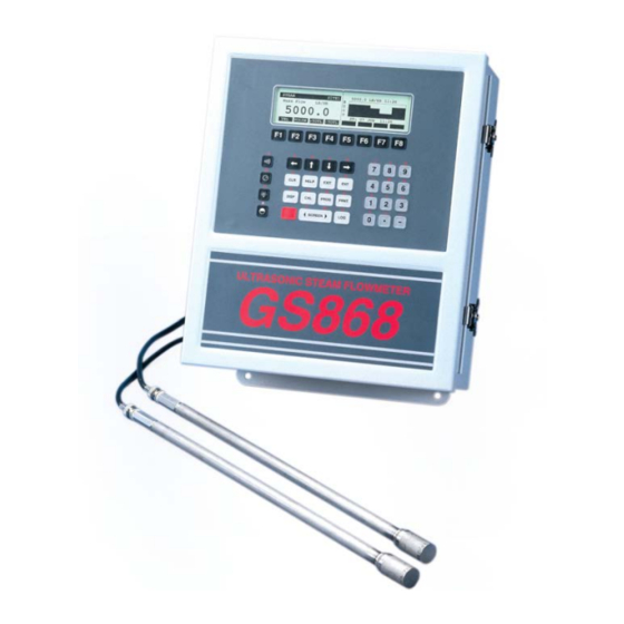
GE DigitalFlow GS868 Startup Manual
Panametrics steam ultrasonic mass flowmeter
Hide thumbs
Also See for DigitalFlow GS868:
- Programming manual (171 pages) ,
- Startup manual (81 pages) ,
- Service manual (74 pages)

Related Manuals for GE DigitalFlow GS868


Summary of Contents for GE DigitalFlow GS868
- Page 1 Measurement & Control Flow DigitalFlow™ GS868 Panametrics Steam Ultrasonic Mass Flowmeter Startup Guide 910-190U Rev. E1 February 2016...
- Page 3 DigitalFlow™ GS868 Panametrics Steam Ultrasonic Mass Flowmeter Startup Guide 910-190U Rev. E1 February 2016 www.gemeasurement.com ©2016 General Electric Company. All rights reserved. Technical content subject to change without notice.
- Page 4 [no content intended for this page]...
- Page 5 Preface Information Paragraphs Note: These paragraphs provide information that provides a deeper understanding of the situation, but is not essential to the proper completion of the instructions. IMPORTANT: These paragraphs provide information emphasizing instructions which are essential to proper setup of the equipment.
- Page 6 Environmental Compliance Waste Electrical and Electronic Equipment (WEEE) Directive GE Measurement & Control is an active participant in Europe’s Waste Electrical and Electronic Equipment (WEEE) take-back initiative, directive 2012/19/EU. The equipment that you bought has required the extraction and use of natural resources for its production. It may contain hazardous substances that could impact health and the environment.
-
Page 7: Table Of Contents
Contents Chapter 1. Installation 1.1 Introduction ................... . 1 1.1.1 Unpacking . - Page 8 Contents Chapter 2. Initial Setup 2.1 Introduction...................23 2.2 Navigating Through the User Program .
- Page 9 Contents Chapter 4. Specifications 4.1 General ....................43 4.1.1 Hardware Configuration .
- Page 10 Contents Appendix D. Measuring P and L Dimensions D.1 Introduction...................61 D.2 Measuring P and L .
-
Page 11: Chapter 1. Installation
To ensure safe and reliable operation of the Model GS868 Steam Ultrasonic Mass Flowmeter, the system must be installed in accordance with the guidelines established by GE’s engineers. Those guidelines, which are explained in detail in this chapter, include the following specific topics: •... -
Page 12: Site Considerations
Chapter 1. Installation 1.2 Site Considerations Because the relative physical locations of the flowcell and the Model GS868 electronics console are important, use the guidelines given in this section to plan the Model GS868 system installation. 1.2.1 Electronics Console Location The standard Model GS868 electronics enclosure is a Type-4X weather-resistant, dust-tight, indoor/outdoor type. -
Page 13: Transducer Cables
Note: When using non-GE cables to connect the flowmeter transducers to the Model GS868 electronics console, the cables must have electrical characteristics identical to the GE cables. Type RG 62 a/u coaxial cable should be used, and each cable must be the same length (within ±4 in.). - Page 14 Chapter 1. Installation Temperature Transmitter Pressure Transmitter Preamp Transducer Flowcell STEAM FLOW Transducer Electronics Console Figure 1: A Typical Model GS868 System DigitalFlow™ GS868 Startup Guide...
-
Page 15: Installing Temperature And Pressure Transmitters
Chapter 1. Installation 1.4 Installing Temperature and Pressure Transmitters Optional temperature and pressure transmitters may be installed as part of the flowcell, near the ultrasonic transducer ports. Be sure to observe the siting requirements given earlier in this chapter. These transmitters must use a 0/4-20 mA signal to transmit the temperature and pressure values to the Model GS868 electronics console. -
Page 16: Mounting The Gs868 Electronic Console
Chapter 1. Installation 1.5 Mounting the GS868 Electronic Console The standard model GS868 electronics package is housed in a Type-4X weather-resistant enclosure. Refer to Figure 9 on page 19 for the mounting dimensions of this enclosure. IMPORTANT: For meters supplied in one of the optional enclosure styles, refer to Appendix C, Optional Enclosures, for specific mounting dimensions and instructions. -
Page 17: Wiring The Line Power
Chapter 1. Installation 1.6.1 Wiring the Line Power ATTENTION EUROPEAN CUSTOMERS! In order to meet CE Mark requirements, all wiring connections must be made in accordance with the instructions in Appendix A, CE Mark Compliance. The Model GS868 may be ordered for operation with power inputs of 100-120 VAC, 220-240 VAC, or 12-28 VDC. The label on the shroud inside the electronics enclosure, just above the line power terminal block, lists the required line voltage and the fuse rating for the unit (the fuse rating is also listed in Chapter 4, Specifications). - Page 18 Chapter 1. Installation 1.6.1 Wiring the Line Power (cont.) 1. Remove the plastic shroud that covers the terminal blocks. Be sure to reinstall the shroud after all of the wiring has been completed. 2. Strip ¼” of insulation from the end of the power and neutral or line leads (or the positive and negative DC power leads), and ½”...
-
Page 19: Wiring The Transducers
Chapter 1. Installation 1.6.2 Wiring the Transducers ATTENTION EUROPEAN CUSTOMERS! In order to meet CE Mark requirements, all wiring connections must be made in accordance with the instructions in Appendix A, CE Mark Compliance. Wiring a typical Model GS868 ultrasonic natural gas flowmeter system requires interconnection of the following components: •... -
Page 20: Wiring The 0/4-20 Ma Analog Outputs
1. Use the information in Table 1 below to construct a suitable cable for connecting the Model GS868 to the external device. If desired, an appropriate cable may be purchased from GE. Table 1: RS232 Connection to DCE or DTE Device... -
Page 21: Wiring The Rs485 Interface
Chapter 1. Installation 1.6.4b Wiring the RS485 Interface Use the optional RS485 serial port to network multiple GS868 flowmeters to a single computer terminal. Upon request, the standard RS232 port on the GS868 may be configured as a two-wire, half-duplex RS485 interface, through a device such as the INMAC Model 800052 RS232-RS422/RS485 converter. -
Page 22: Wiring The Ethernet Interface
Chapter 1. Installation 1.6.4c Wiring the Ethernet Interface A modified GS868 can use the Ethernet interface to communicate to an internal network. An optional Ethernet card with a unique MAC (IP) address (installed only in slots 5 or 6) includes an RJ45 connector. To connect the Ethernet- enabled GS868 to the network, insert the jack of an RJ45 cable into the RJ45 connector, route the cable through the bottom of the GS868, and wire the other end of the cable to the Ethernet network according to the manufacturer’s instructions. -
Page 23: Wiring The Foundation Fieldbus Network
Chapter 1. Installation 1.6.5 Wiring the Foundation Fieldbus Network Fieldbus network connections are made at J8/J9, pins 1 and 2 (see Figure 5 below). Optionally, a shield can be connected to J8/J9 pin 3, depending on the network wiring. Connector J8 or J9 will be installed depending on the option ordered by the customer. -
Page 24: Wiring An Alarms Option Card
Chapter 1. Installation 1.6.6 Wiring an Alarms Option Card The Model GS868 flowmeter can accommodate up to 4 alarms option cards. Each alarms option card includes three Form C relays (designated as A, B and C). The alarm relays on the option card are available in two types: •... -
Page 25: Wiring A 0/4-20 Ma Analog Inputs Option Card
Chapter 1. Installation 1.6.7 Wiring a 0/4-20 mA Analog Inputs Option Card To calculate the standard mass flow rates of the steam, the Model GS868 requires accurate temperature and pressure data from the measurement site. Transmitters installed in the flowcell can provide this information via an optional 0/4- 20 mA analog inputs card. -
Page 26: Wiring A Totalizer/Frequency Outputs Option Card
Chapter 1. Installation 1.6.7 Wiring a 0/4-20 mA Analog Inputs Option Card (cont.) Wire the analog input terminal block in accordance with the pin number assignments shown in Figure 10 on page 20. The standard Model GS868 has at least one analog inputs option card, which is used to supply the live pressure reading required for accurate mass flow calculations. -
Page 27: Wiring An Rtd Inputs Option Card
Chapter 1. Installation 1.6.9 Wiring an RTD Inputs Option Card The Model GS868 can accommodate up to four RTD (Resistance Temperature Device) inputs option cards. Each RTD inputs option card provides two direct RTD inputs (designated as A and B). The standard Model GS868 has at least one RTD inputs option card, which is used to supply the live temperature reading required for accurate mass flow calculations. - Page 28 Chapter 1. Installation [no content intended for this page] DigitalFlow™ GS868 Startup Guide...
- Page 29 Chapter 1. Installation Ø0.38 (10), 4 Places 0.75 (19) 1.40 (36) 8.00 (203) 2.87 (73) 14.24 13.00 13.49 7.00 (362) (330) (343) (178) Ø0.13 (3), 4 Places 2.69 (68) 5.10 (129) 11.37 (289) 10.74 (273) 3/4" Conduit Plate Ø1.10 (28), 6 Places 1/2"...
- Page 30 Chapter 1. Installation RS232 SERIAL PORT RS485 PORT (MODBUS) Pin # Description Pin # Description RTN - Digital Return TMT- TX - Transmit TMT+ RX - Receive Unused DTR - Data Terminal Ready Unused CTS - Clear to Send Unused WARNING CH2 TRANSDUCER Pin #...
- Page 31 POWER SUPPLY (UP TO 1000 FEET) PRESSURE TRANSMITTER FLOW SUPPLIED BY GE (REFERENCE ONLY) PRESSURE INPUT COAXIAL CABLES, BNC TO BNC GS868 (SUPPLIED BY GE) 10 FOOT PIN # TRANSDUCER (REF ONLY) PIPE (REF ONLY) 24V+ SENSOR +IN1 -OUT -IN1...
- Page 32 Chapter 1. Installation DigitalFlow™ GS868 Startup Guide...
-
Page 33: Chapter 2. Initial Setup
Chapter 2. Initial Setup Chapter 2. Initial Setup 2.1 Introduction This chapter provides instructions for entering the minimum amount of programming data required to place the Model GS868 flowmeter into operation. Before the Model GS868 can begin taking measurements and displaying valid data, the current system and pipe parameters must be entered. -
Page 34: Accessing The User Program
Chapter 2. Initial Setup 2.3 Accessing the User Program [PROG] To access the User Program, press the key on the keypad. Note: If the security feature is active, enter the password and press the [ENT] key to enter the User Program. See the SECUR submenu section in Chapter 1, Programming Site Data, of the Programming Manual for more information. -
Page 35: Activating A Channel
Chapter 2. Initial Setup 2.4 Activating a Channel ACTIV submenu permits selection of the desired measurement method. In addition, it is used to activate/deactivate one or both of the channels in a 2-Channel Model GS868. 2.4.1 1-Channel Meter ACTIV [F1] User PROGRAM 1. -
Page 36: Entering System Data For A Channel
Chapter 2. Initial Setup 2.5 Entering System Data for a Channel SYSTM Begin the programming of the submenu in either the 1-Channel or 2-Channel section below. 2.5.1 A 1-Channel Meter SYSTM For the 1-Channel Model GS868, the information entered in the submenu pertains to the global operation of the flowmeter. -
Page 37: A 2-Channel Meter
Chapter 2. Initial Setup 2.5.2 A 2-Channel Meter SYSTM For the 2-Channel Model GS868, the information entered in the submenu pertains only to the currently selected channel. [F2] SYSTM 1. At the User Program screen shown, press the function key to program the submenu. - Page 38 Chapter 2. Initial Setup 2.5.3 1- and 2-Channel Meters (cont.) [F1]-[F4] 6. Use the keys to select the Total Decimal Digits (the desired number of digits to the right of the decimal point) in the totalized flow display. Static Density? ADVAN SETUP 7.
-
Page 39: Entering Pipe Data
Chapter 2. Initial Setup 2.6 Entering Pipe Data PIPE submenu permits entry of the transducer and pipe specifications. To program this menu, complete the following steps: [F3] PIPE 1. At the User (or Channel) Program screen, press to program the submenu. -
Page 40: Path Length
Chapter 2. Initial Setup 2.6.4 Path Length [F1] [F2] = feet 5. Press = inch or to select the units. Then, enter the Path Length (P) of the ultrasonic signal. Press [ENT] . (The meter will only accept values from 1/8 to 900 in.) Note: The factory has calculated both the transducer signal path length and the transducer signal axial length based on the exact transducer configuration used for the application. - Page 41 Chapter 2. Initial Setup Procedure Options User (or Channel) PROGRAM After completing the above steps, the meter returns to the prompt. Continue as follows: • To continue programming the meter, refer to the menu maps in Appendix A of the Programming Manual and navigate to the desired menu.
- Page 42 Chapter 2. Initial Setup DigitalFlow™ GS868 Startup Guide...
- Page 43 Chapter 2. Initial Setup PROG (2-Channel)) (1-Channel) NOTE: Plain text represents prompt area messages and boxed text represents option bar choices. Fx represent function keys to select option bar choices. GLOBL SAVE Channel PROGRAM status PROGRAM status ACTIV SYSTM PIPE (2-Channel) (1-Channel) (2-Channel)
- Page 44 Chapter 2. Initial Setup DigitalFlow™ GS868 Startup Guide...
-
Page 45: Chapter 3. Operation
Chapter 3. Operation Chapter 3. Operation 3.1 Introduction See Chapter 1, Installation, and Chapter 2, Initial Setup, to prepare the system for operation. When the meter is ready to take measurements, proceed with this chapter. The following specific topics are discussed: •... -
Page 46: Powering Up
1.8 m (6 ft) of the Model GS868. Immediately upon power up, the Model GS868 displays the GE logo and the software version in the left pane of the display window. The Model GS868 performs a series of internal checks and display the results in the right pane of the display window. -
Page 47: Using The Display
Chapter 3. Operation 3.3 Using the Display The Model GS868 display is divided into a left pane and a right pane. The two screen panes can be set independently to display any of the available measurement or diagnostic parameters. The components of a typical measurement mode screen are shown in Figure 14 below. - Page 48 Chapter 3. Operation Using the Display (cont.) At various times, one or more of the following four symbols may be displayed on the far right of the locator bar: • : This symbol, which is called the pointer, indicates that additional option bar entries are available. These options can be accessed by using the ] and ] keys.
-
Page 49: Taking Measurements
Chapter 3. Operation 3.4 Taking Measurements The Model GS868 is capable of displaying several different variables in a variety of formats. However, this manual will only discuss the basic measurement displays in the default screen format. Refer to the Programming Manual for instructions on setting up alternate screen displays and see the Service Manual for a discussion of the diagnostic DIAG parameters listed under the... - Page 50 Chapter 3. Operation Taking Measurements (cont.) Table 8: Measurement Parameter Options Option Bar Choice Description [F1] Flow Velocity [F2] VOLUM Volumetric Flow [F3] +TOTL Forward Totalized Volume Flow [F4] -TOTL Reverse Totalized Volume Flow ] + [F1] TIME Total Flow Measurement Time ] + [F2] MDOT...
-
Page 51: Foundation Fieldbus Communications
Chapter 3. Operation 3.4.1 Foundation Fieldbus Communications Foundation Fieldbus provides a means of communicating with the flowmeter. The patent numbers which apply are 5,909,363 and 6,424,872. This Foundation Fieldbus device supports 2 Analog Input (AI) blocks, which can be configured to supply the following measurements on the network (see Table 9 below). - Page 52 Chapter 3. Operation [no content intended for this page] DigitalFlow™ GS868 Startup Guide...
-
Page 53: Chapter 4. Specifications
Chapter 4. Specifications Chapter 4. Specifications 4.1 General The general specifications for the Model GS868 flowmeter are divided into the following categories: 4.1.1 Hardware Configuration Package Options: Epoxy-coated aluminum (standard) Stainless steel Explosion-proof Physical: Size: 14.24 11.4 5.12 in. (36.2 29 13 cm) Weight: 11 lb (5 kg) 4.1.2 Environmental Operating Temperature: -4°... -
Page 54: Electrical
Chapter 4. Specifications 4.2 Electrical The electrical specifications for the Model GS868 flowmeter are divided into the following categories: 4.2.1 Power Supply Input Options: 110 to 120 VAC, 50/60 Hz with 1.0 A Slo-Blo Fuse 220 to 240 VAC, 50/60 Hz with 0.5 A Slo-Blo Fuse 12 to 28 VDC with 3.0 A Slo-Blo Fuse 4.2.2 Power Usage 20 W maximum... - Page 55 Chapter 4. Specifications 4.2.5 Input/Output Specifications (cont.) Analog Input Options (cont.): a. Temp from –200° to +1,000°C Pressure from 0–3000 psig 0 to 500 bar c. Steam quality from 0.0 to 1.0 Analog Output Options: All meters come with two isolated 0/4–20 mA current outputs (550 maximum load). Optional selection of up to 3 additional output boards, each with four isolated 0/4–20 mA outputs (1000 ...
-
Page 56: Operational
Chapter 4. Specifications 4.3 Operational The operational specifications for the Model GS868 flowmeter are divided into the following categories: 4.3.1 Flow Computer (Built-in) The flow computer has three operating modes: 1. RUN (Normal operating mode): Flow velocity equations are solved and statistical data rejection techniques are employed to provide reliable and repeatable results. -
Page 57: Transducer
Chapter 4. Specifications 4.4 Transducer The transducer specifications for the Model GS868 flowmeter are divided into the following categories: 4.4.1 Type Standard: T9 Optional: BWT™ System 4.4.2 Temperature Range –190° to 450°C (–310° to 842°F) (overall) 4.4.3 Pressure Ranges Standard: 0 to 2700 psig (1 to 187 bar) Optional: 3480 psig (240 bar) maximum 4.4.4 Materials Standard: Stainless steel, titanium... -
Page 58: Flowcell
Process Connections: Transducer Connection: PanaPort cold tap kit Optional: ANSI flanged 150 to 300# Pipe Size & Materials Outside Diameter (OD): 2 to 48 in. (50 to 1200 mm). Materials: All metals. Consult GE for other materials. DigitalFlow™ GS868 Startup Guide... -
Page 59: Appendix A. Ce Mark Compliance
Appendix A. CE Mark Compliance Appendix A. CE Mark Compliance A.1 Introduction For CE Mark compliance, the Model GS868 flowmeter must be wired in accordance with the instructions in this appendix. IMPORTANT: CE Mark compliance is required only for units intended for use in EC countries. A.2 Wiring The Model GS868 must be wired with the recommended cable, and all connections must be properly shielded and grounded. - Page 60 Appendix A. CE Mark Compliance [no content intended for this page] DigitalFlow™ GS868 Programming Manual (1-Channel)
-
Page 61: Appendix B. Data Records
Appendix B. Data Records Appendix B. Data Records B.1 Option Cards Installed Whenever an option card is installed in one of the Model GS868’s expansion slots, record the type of card and any additional setup information in the appropriate row of Table 11 below. Table 11: Option Cards Installed Slot # Type of Option Card... -
Page 62: Initial Setup Data
Appendix B. Data Records B.2 Initial Setup Data After the Model GS868 flowmeter has been installed, some initial setup data must be entered via the User Program, prior to operation. Record that information in Table 12 below. Table 12: Initial Setup Data General Information Model # Reference... - Page 63 Appendix B. Data Records Table 12: Initial Setup Data (cont.) Pipe/Transducer Parameters (cont.) - PIPE Channel 1 (cont.) Channel 2 (cont.) Pipe O.D. Pipe O.D. Pipe Wall Pipe Wall Path Length (P) Path Length (P) Axial Length (L) Axial Length (L) Fluid Type Steam Other...
- Page 64 Appendix B. Data Records [no content intended for this page] DigitalFlow™ GS868 Startup Guide...
-
Page 65: Appendix C. Optional Enclosures
Appendix C. Optional Enclosures Appendix C. Optional Enclosures C.1 Introduction Upon request the Model GS868 flowmeter may be supplied in an enclosure other than the standard Type-4X enclosure described in Chapter 1, Installation, of this manual. Although the standard installation and wiring instructions still apply in general terms, some of the details may vary for different enclosure types. -
Page 66: Rack Mount Front Panel
Appendix C. Optional Enclosures Rack Mount Wiring (cont.) Note: The pins on the option card connectors are numbered from pin #1 on the top to pin #8 (or #9) on the bottom. 6. Place the power switch (item #1) in the ON position. The Model GS868 is now completely wired. - Page 67 Appendix C. Optional Enclosures 14.83 (377) 4.19 (106) 16.99 (432) 11.82 11.37 (300) (289) 13.13 (333) 15.70 (399) 3.31 (84) HELP EXIT 2.25 5.22 (57) (133) DISP PROG PRNT SCREEN GS868 18.25 (464) 19.00 (483) DigitalFlow™ GS868 Startup Guide...
- Page 68 Appendix C. Optional Enclosures RS232 SERIAL PORT (DB9) CH2 TRANSDUCER NOTE: For compliance with the European Union's Low Voltage BNC # Description Pin # Description Directive, this unit requires an external power Upstream XDCR No Connection disconnect device such as a switch or circuit breaker. The Downstream XDCR TX - Transmit disconnect device must be marked as such, clearly visible,...
- Page 69 Appendix C. Optional Enclosures Mounting Holes Mounting Holes Handle Handle HELP EXIT DISP PROG PRNT SCREEN GS868 LCD Display Main Keypad Function Keys Console Keys DigitalFlow™ GS868 Startup Guide...
- Page 70 Appendix C. Optional Enclosures DigitalFlow™ GS868 Startup Guide...
- Page 71 – Standard GE 90° transducers have the face offset from the centerline of the body by 0.6 inches. Thus, a pair of transducers has a total offset of 1.2 inches, as indicated in Equation D-2 above. For example, suppose that the transducer installation angle is 30°...
- Page 72 Appendix D. Measuring P and L Dimensions 180° Installation Pipe Thickness Pipe O.D. Bias 90° Installation Figure 18: Top View of Transducer Installations DigitalFlow™ GS868 Startup Guide...
- Page 73 Index ....27 Display Abbreviations, Volumetric Units ..... 39 .
- Page 74 Index Preamplifier ......9 Connecting ....9 Lightning Protector, Connecting Pressure Transmitter .
- Page 75 Index ......26 SYSTM Submenu ..... . . 26 for 1-Channel Meter .
- Page 76 Index DigitalFlow™ GS868 Startup Guide...
- Page 77 AUTHORIZATION NUMBER (RAN), and shipping instructions for the return of the instrument to a service center will be provided. 2. If GE Sensing instructs you to send your instrument to a service center, it must be shipped prepaid to the authorized repair station indicated in the shipping instructions.
- Page 78 Warranty [no content intended for this page] DigitalFlow™ GS868 Startup Guide...
- Page 79 Cable glands of an approved flameproof design are required for Ex d rated equipment. These must be installed according to the manufacturer’s instructions. Where the cable glands are provided by GE, the manufacturer’s instructions, as supplied to GE, will be included in the documentation.
- Page 80 Certification & Safety Statements for GE Infrastructure Products Used in Hazardous Locations August 2014 Special Conditions for Safe Use Consult the manufacturer if dimensional information on any flameproof joint is necessary. Follow the manufacturer’s instructions to reduce the potential of an electrostatic charging hazard.
- Page 81 EC DECLARATION Sensing CONFORMITY DOC-0013, Rev. C GE Sensing 1100 Technology Park Drive Billerica, MA 01821 declare under our sole responsibility that the DigitalFlow™ DF8688 Liquid Ultrasonic Flowmeter DigitalFlow™ GC868 Clamp-On Gas Ultrasonic Flowmeter DigitalFlow™ GF868 Flare Gas Mass Ultrasonic Flowmeter DigitalFlow™...
- Page 84 Customer Support Centers U.S.A. The Boston Center 1100 Technology Park Drive Billerica, MA 01821 U.S.A. Tel: 800 833 9438 (toll-free) 978 437 1000 E-mail: sensing@ge.com Ireland Sensing House Shannon Free Zone East Shannon, County Clare Ireland Tel: +353 (0)61 470200 E-mail: gesensingsnnservices@ge.com An ISO 9001:2008 Certified Company www.gemeasurement.com/en/about-us/quality.html...