Table of Contents
Advertisement
ELECTROLUX HOME PRODUCTS PTY LTD
ABN 51 004 762 341
Technical Publication Nº RESI219
WEB SITE ADDRESS: www.partnship.com.au
ELECTRONICALLY CONTROLLED
*06
Dual Inlet Water Valve replaces
Triple Inlet Water Valve.
© Copyright 2008 ELECTROLUX HOME PRODUCTS PTY LTD Technical Services
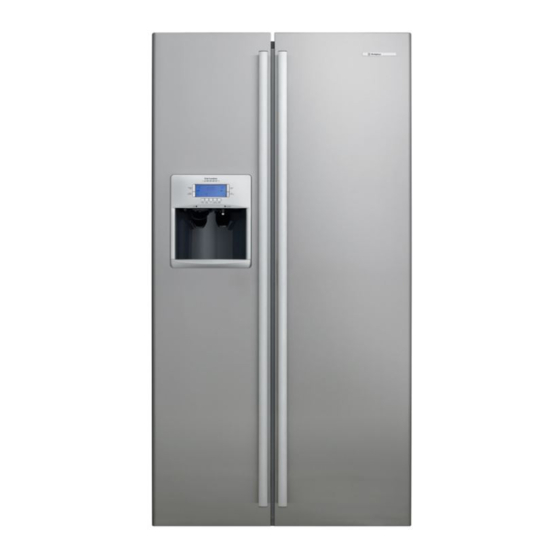
WESTINGHOUSE
" B " SERIES
COMPACT
SIDE BY SIDE
REFRIGERATOR
MODELS:
WSE6070PB *06
WSE6070SB *06
WSE6070WB *06
(ICE & WATER) PACIFIC SILVER
(ICE & WATER) STAINLESS STEEL
(ICE & WATER) WHITE
Issue: 1
Date: 4/08
Advertisement
Table of Contents

Related Manuals for Electrolux B Series


Summary of Contents for Electrolux B Series
- Page 1 Dual Inlet Water Valve replaces Triple Inlet Water Valve. MODELS: WSE6070PB *06 (ICE & WATER) PACIFIC SILVER WSE6070SB *06 (ICE & WATER) STAINLESS STEEL WSE6070WB *06 (ICE & WATER) WHITE © Copyright 2008 ELECTROLUX HOME PRODUCTS PTY LTD Technical Services...
-
Page 2: Table Of Contents
INDEX SECTION PAGE Nº Index Specifications The Parts Of The Refrigerator Electronic Control Information 5 - 7 Thermal Fuse Setting The Electronics 8 - 13 Diagnostics 14 - 20 Remove/Replace Control Board Introduction To Ice Maker 22 - 25 Ice Making Operating Cycle 26 - 31 Installation Of Water Line Ice Maker Parts Replacement... -
Page 3: Specifications
SPECIFICATIONS DESCRIPTION WSE6070PB *06 WSE6070SB *06 WSE6070WB *06 DIMENSIONS Height (mm) 1754 Width (mm) Depth (mm) Depth (mm) (With Door Open 90º) 1110 Total Gross Volume (litres) COMPRESSOR Part Nº 1450247 Embraco Type EGYS100 Start Winding (ohms) 26.00 Run Winding (ohms) 11.18 Full Load (Amps) 0.96... -
Page 4: The Parts Of The Refrigerator
Page 4 RESI219... -
Page 5: Electronic Control Information
ELECTROLUX ELECTRONICS The top of the range cabinets will be fitted with an Electrolux Electronic control. This consists of a Control Board, Relay Board, User Interface (Control Display) and Two Sensors. Functionally this replaces the thermostat and defrost timer and provides some extra features. - Page 6 • If the freezer fan and compressor are off, the temperature of the food compartment must rise another 2ºC before the freezer fan motor is activated. The compressor will not switch on until the freezer sensor reaches its set point. For each half hour of a 24 hour period, the amount of time the door is open for the half hour is recorded.
-
Page 7: Thermal Fuse
Sensors: The practise of testing the sensors in an ice bath is not an option with the new electronics. The configeration of the electronics is such that there is a floating 240 volts AC in the sensor wiring. If for any reason the insulation breaks down the sensor wiring will be live. -
Page 8: Setting The Electronics
Page 8 RESI219... - Page 9 Page 9 RESI219...
- Page 10 Page 10 RESI219...
- Page 11 Page 11 RESI219...
- Page 12 Page 12 RESI219...
- Page 13 Page 13 RESI219...
-
Page 14: Diagnostics
Page 14 RESI219... - Page 15 Page 15 RESI219...
- Page 16 Page 16 RESI219...
- Page 17 Page 17 RESI219...
- Page 18 Page 18 RESI219...
- Page 19 Page 19 RESI219...
- Page 20 Page 20 RESI219...
- Page 21 REMOVAL AND REPLACEMENT OF THE CONTROL BOARD Before performing the following, ensure that the power is removed from the cabinet by switching off the mains supply and disconnecting the service cord from the power outlet. Move the cabinet to a position, which will allow easy access to the machine compartment. Discharge any static electricity that you may be carrying by touching any exposed metal part of the cabinet.
-
Page 22: Introduction To Ice Maker
AUTOMATIC ICE MAKER The automatic ice maker is mounted in the freezer compartment. It is attached to the auger motor and cradle assembly with two screws and may be removed for servicing. The ice maker is designed to produce ice cubes automatically. The length of the time between harvest cycles will vary, depending on load condition, door openings, ambient temperature and freezer temperature. - Page 23 Mould Heater A mould heater, rated at 115 watts and covered with an aluminium sheath, is embedded in the grooved section on the underside of the mould. When the mould heater is energised, heat melts the ice contact surface within the mould, allowing harvest of the ice pieces. The mould heater is wired in series with the ice maker thermostat, which acts as a safety device.
- Page 24 Timing Switches The three timing switches used are of the single-pole, double-throw type (See Figure D2). They are identical except for function, and can be used interchangeably. • Holding Switch – assumes completion of a revolution once the ice maker operation has started. •...
- Page 25 Diode Used to drop the 240v input to a 115v supply voltage to the mould heater. TCO – Thermal Cut-Out The thermal cut-out is a one time, limit fuse used as a safety device. It is located under the mounting plate, in the head of the ice maker, between the thermostat and the wire connector.
-
Page 26: Ice Making Operating Cycle
OPERATING CYCLE The operation of the ice maker, water refilling, and controlled ice storage, require proper functioning and timing of all the components. Consider the following: 1. Has the refrigerator been properly installed and connected to sources of electrical power and water. - Page 27 OPERATING CYCLE ILLUSTRATIONS - MECHANICAL Page 27 RESI219...
- Page 28 Page 28 RESI219...
- Page 29 OPERATING CYCLE ILLUSTRATIONS - ELECTRICAL Page 29 RESI219...
- Page 30 Page 30 RESI219...
- Page 31 Page 31 RESI219...
- Page 32 INSTALLING WATER SUPPLY LINE TO ICE MAKER Make sure the installation complies with all applicable plumbing codes. The ice maker kit contains ¼” plastic tubing and the fittings required to connect the plastic tube to the water valve at the rear of the refrigerator and the fitting on the supply water pipe. The ice maker should be connected to a frequently used cold water pipe to ensure a fresh water supply.
-
Page 33: Ice Maker Parts Replacement
PARTS REMOVAL & REPLACEMENT (FOR INFORMATION ONLY, MOST INDIVIDUAL PARTS NOT AVAILABLE) First, disconnect the refrigerator service cord from the power supply. If the refrigerator is operating and cold, allow the ice maker to warm up to room temperature before removing the front cover. This prevents moisture from condensing on the metal components. - Page 34 To Remove & Replace the Motor 1. Remove the front cover. 2. Remove the three screws that attach the mounting plate to the support housing. 3. Disconnect the motor leads. 4. Remove the two motor mounting screws. 5. Replace in the reverse order. To Remove &...
-
Page 35: Ice Maker Diagnostics
To Remove & Replace Mould Heater 1. Remove the front cover. 2. Remove the ice stripper. 3. Remove the three screws that attach the mounting plate to the support housing. 4. Remove the two screws that attach the mould to the support housing. 5. - Page 36 Complaint – Ice Maker Fails to Stop at the End of the Cycle Cause- 1. With the ejector blades in the standing position, check the holding switch terminals “C” and “NO” for continuity. Replace the switch if closed. Complaint – Ice Maker Continues To Eject when Container is Full Cause- 1.
- Page 37 Page 37 RESI219...
-
Page 38: Removal Of The Ice And Water Dispenser Fascia Assy
DOOR GASKET REMOVAL Page 38 RESI219... -
Page 39: Remove/Replace Door Gaskets
DOOR GASKET REMOVAL Page 39 RESI219... - Page 40 Page 40 RESI219...
- Page 41 DOOR GASKET REPLACEMENT Gasket Profiles Page 41 RESI219...
-
Page 42: Removal Of The Control Housing Relay Board, Bulb Light, Strip Light And
Page 42 RESI219... - Page 43 Page 43 RESI219...
- Page 44 Page 44 RESI219...
-
Page 45: Removal Of Evaporator Cover, Upper Air Duct Cover, Fan Housing And
REMOVAL OF THE THE UPPER AIR DUCT COVER, EVAPORATOR COVER, FAN HOUSING & EVAPORATOR ASSEMBLY Page 45 RESI219... -
Page 46: Removal Of The Freezer Fan, Dtt & Heater Harness Connections
REMOVAL OF THE FREEZER FAN, D.T.T., & HEATER HARNESS CONNECTIONS Page 46 RESI219... -
Page 47: To Access The Food Compartment & Freezer Sensor
TO ACCESS THE FREEZER & FOOD COMPARTMENT SENSORS The Freezer Sensor is located on the left hand side freezer compartment wall. The Food Compartment Sensor is located on the right hand side of the rear liner above the top crisper. Remove the two screws securing the housing. -
Page 48: Removal Of The Ice Cream Shelf
Page 48 RESI219... -
Page 49: Removal Of The Ice Bin Cradle And Ice Maker Assembly
Page 49 RESI219... -
Page 50: Removal Of Ice Maker From The Ice Bin Cradle
Page 50 RESI219... - Page 51 Page 51 RESI219...
-
Page 52: Removal Of The Freezer Light Globe
REMOVAL OF THE FREEZER LIGHT GLOBES Page 52 RESI219... -
Page 53: Access To The Control Board, Compressor, Condenser, Condenser Fan
ACCESS TO THE CONTROL BOARD, COMPRESSOR, CONDENSER FAN, CONDENSER & WATER VALVES. Page 53 RESI219... -
Page 54: Water Flow Schematic Diagram
MODELS: WSE6070PB *06 EX. VIEW DRAWING R1046 WSE6070SB *06 SCHEMATIC DIAGRAM OF WSE6070WB *06 WATER FLOW Page 54 RESI219... -
Page 55: Air Flow
MODELS: WSE6070PB *06 AIR FLOW R757 WSE6070SB *06 WSE6070WB *06 Page 55 RESI219... - Page 56 MODELS: WSE6070PB *06 AIR FLOW R1051 WSE6070SB *06 WSE6070WB *06 Page 56 RESI219...
-
Page 57: Top Hinge Wiring
TOP HINGE WIRING The top hinge wiring is as follows: Black 0v dc (Control / Power Board) Brown +12v dc (Relay Board) (+12v dc between the Brown and Grey wires) +12v dc (Control / Power Board) (+5v dc between the Red and Black wires) Orange Display Signal (Control / Power Board) Yellow... -
Page 58: Relay Board Wiring Diagram
WSE6070WB *06 IMPORTANT SAFETY NOTICE This diagram has been prepared for use by electrically qualified service technicians. Electrolux cannot be held responsible for the interpretation of its service publications nor for any injury or damage that may occur in connection with their use. -
Page 59: Voltages Relay Board
WSE6070WB *06 IMPORTANT SAFETY NOTICE This diagram has been prepared for use by electrically qualified service technicians. Electrolux cannot be held responsible for the interpretation of its service publications nor for any injury or damage that may occur in connection with their use. -
Page 60: Control Board Diagram
WSE6070WB *06 IMPORTANT SAFETY NOTICE This diagram has been prepared for use by electrically qualified service technicians. Electrolux cannot be held responsible for the interpretation of its service publications nor for any injury or damage that may occur in connection with their use. -
Page 61: Circuit Diagram For Electronic / Ice Maker Models
WSE6070WB *06 IMPORTANT SAFETY NOTICE This diagram has been prepared for use by electrically qualified service technicians. Electrolux cannot be held responsible for the interpretation of its service publications nor for any injury or damage that may occur in connection with their use. - Page 62 Release Date WSE6070PB *06 01/8/2007 WSE6070SB *06 01/8/2007 WSE6070WB *06 01/8/2007 Page 62 RESI219...