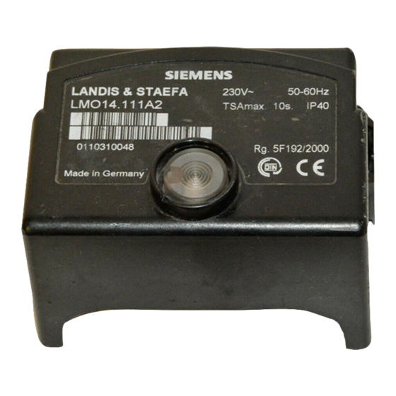
Siemens LMO14 Series Manual
Oil burner controls
Hide thumbs
Also See for LMO14 Series:
- Manual (14 pages) ,
- Manual (12 pages) ,
- Installation instructions manual (40 pages)
Advertisement
Quick Links
ISO 9001
Use
Application-specific
features
CC1N7130en
31.07.2000
Oil Burner Controls
Microcontroller-based oil burner controls for the supervision, start-up and con-
trol of forced draught oil burners in intermittent operation. Oil throughput up to
30 kg / h with the LMO14... and LMO24..., and above 30 kg / h with the LMO44...
The LMO14..., LMO24..., LMO44... and this data sheet are intended for OEMs
which integrate the burner controls in their products.
The LMO... burner controls are designed for the start-up and supervision of single- or 2-
stage forced draught oil burners in intermittent operation.
Yellow-burning flames are supervised with photoresistive detectors QRB..., blue-
burning flames with blue-flame detectors QRC...
In terms of housing dimensions, electrical connections and flame detectors, the LMO...
are identical to the LOA... oil burner controls.
Forced draught oil burners conforming to EN 267
-
LMO44... for stationary direct-fired air heaters
-
Burner controls for use with atomization oil burners of monoblock design conform-
-
ing to EN 230
Detection of undervoltages
-
Electrical remote reset
-
Contact for oil pre-heating
-
Monitoring of time for oil pre-heating
-
Accurate and reproducible program sequence thanks to digital signal handling
-
Controlled intermittent operation after 24 hours of continuous operation
-
Limitation of the number of repetitions
-
Multicolour indication of fault and status messages
-
Siemens Building Technologies
Landis & Staefa Division
7
130
LMO14...
LMO24...
LMO44...
Advertisement

Summary of Contents for Siemens LMO14 Series
- Page 1 Accurate and reproducible program sequence thanks to digital signal handling Controlled intermittent operation after 24 hours of continuous operation Limitation of the number of repetitions Multicolour indication of fault and status messages Siemens Building Technologies CC1N7130en Landis & Staefa Division 31.07.2000...
- Page 2 40 seconds Burner operation with simulated flame Restart followed by lock-out at failure; for that purpose, darken the flame the end of «TSA» detector during operation and maintain that status 2/10 Siemens Building Technologies CC1N7130en Landis & Staefa Division 31.07.2000...
- Page 3 LOA44.252A27 TSAmax. Maximum ignition safety time Legend Waiting time Pre-purge time Pre-ignition time Post-ignition time, maximum until the end of «TSAmax» Interval from flame signal to the release of «BV2» 3/10 Siemens Building Technologies CC1N7130en Landis & Staefa Division 31.07.2000...
- Page 4 Test adapter KF8885 With switch for manual start-up of burner With switch for simulating the oil pre-heater’s release contact With 2 pairs of jacks for measuring the flame detector current 4/10 Siemens Building Technologies CC1N7130en Landis & Staefa Division 31.07.2000...
- Page 5 LMO44... Type reference QRC... Min. detector current Max. detector current Max. possible with required (with flame) permitted flame (typically) (without flame) LMO14... LMO24... 70 µA 5.5 µA 100 µA LMO44... 5/10 Siemens Building Technologies CC1N7130en Landis & Staefa Division 31.07.2000...
- Page 6 ACS400 can be used. In that case, connection of the DC microammeter is not required. Legend µA DC DC microammeter with an internal resistance of Ri = max. 5 kΩ Blue Black Brown 6/10 Siemens Building Technologies CC1N7130en Landis & Staefa Division 31.07.2000...
- Page 7 Green-off Undervoltage Yellow-red Fault, alarm Output of fault code (refer to «Fault Red-off code table») Extraneous light prior to burner start- Green-red Interface diagnosis Red flicker light Legend Yellow Green 7/10 Siemens Building Technologies CC1N7130en Landis & Staefa Division 31.07.2000...
- Page 8 The diagnosis of the cause of fault is quit and the burner switched on again by resetting the burner control. Press lock-out reset button for about 1 second (< 3 seconds). 8/10 Siemens Building Technologies CC1N7130en Landis & Staefa Division 31.07.2000...
-
Page 9: Control Sequence
Time of flame establishment heater Operating position Beginning of start-up sequence with burners using no oil pre- Controlled shut-down by «R» heater Control signals µC1 Microcontroller 1 Required input signals µC2 Microcontroller 2 9/10 Siemens Building Technologies CC1N7130en Landis & Staefa Division 31.07.2000... - Page 10 Connection of earthing lug «C» and fixing screws in «A» to burner ground → Use a metric screw with a lockwasher or similar! 2000 Landis & Staefa Produktion GmbH 10/10 Siemens Building Technologies CC1N7130en Landis & Staefa Division 31.07.2000...


