Table of Contents
Advertisement
■
This manual is common to all the models regardless of suffixes of the Model No.
・K: Black model
・W: White model
■
Points of difference between the RZ370/RW330 series
・Contrast ratio 10 000:1 → 20 000:1
・Added "EDGE BLENDING" function
・Added "BRIGHTNESS CONTROL" function
・Equipped with "3D SYNC" terminal and added "3D projection" function
(VESA standard IR system,DLP Link system)
・Available in portrait setting
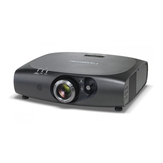
1-chip DLP Based Projector
PT-RZ470U
Model No.
PT-RZ470E
PT-RZ470EA
PT-RW430U
PT-RW430E
PT-RW430EA
© Panasonic Corporation 2013. Unauthorized
copying and distribution is a violation of law.
ORDER NO. VED1302461CE
D10
Rev.-2 (2018-01)
Advertisement
Chapters
Table of Contents
Troubleshooting

Related Manuals for Panasonic PT-RZ470 Series


Summary of Contents for Panasonic PT-RZ470 Series
- Page 1 ・Added "EDGE BLENDING" function ・Added "BRIGHTNESS CONTROL" function ・Equipped with "3D SYNC" terminal and added "3D projection" function (VESA standard IR system,DLP Link system) ・Available in portrait setting © Panasonic Corporation 2013. Unauthorized copying and distribution is a violation of law. Rev.-2 (2018-01)
- Page 2 IMPORTANT SAFETY NOTICE There are special parts used in Panasonic DLP Projectors which are important for safety. These parts are shaded on the schematic diagram. It is essential that these critical parts should be replaced with manufacturer’s specified parts to prevent shock, fire, or other...
- Page 3 WARNING: This equipment has been tested and found to comply with the limits for a Class A digital device, pursuant to Part 15 of the FCC Rules. These limits are designed to provide reasonable protection against harmful interference in a residential installation. This equipment generates, uses and can radiate radio frequency energy and, if not installed and used in accordance with the instructions, may cause harmful interference to radio communications.
-
Page 4: Table Of Contents
TABLE OF CONTENTS ■ COVER PAGE 1. Safety Precautions 2. Specifications SECTION 1 <Service Information> ■ 1. The name of each part 2. Menu Navigation 3. Service Mode 4. External Controls 5. Cautions for Service 6. Troubleshooting SECTION 2 <Disassembly Procedures> ■... -
Page 5: Safety Precautions
1. Safety Precautions 1.1. General Guidelines - For continued safety, no modification of any circuit must be attempted. - Unplug the power cord from the power outlet before disassembling this projector. - Use correctly the supplied power cord and must ground it. - It is advisable to use an isolation transformer in the AC power line before the service. -
Page 6: Specifications
2. Specifications... - Page 8 SECTION 1 Service Information PT-RZ470 Series Model No. PT-RW430 Series CONTENTS 1. The name of each part ・・・・・・・・・・・・・・・・・・・・・・・・・・・・・・・・・・・・・・・・・・・・・・・・・・ INF-2 1. 1. Projector body 1. 2. Control panel 1. 3. Connecting terminals 1. 4. Remote control 2. OSD Menu Navigation ・・・・・・・・・・・・・・・・・・・・・・・・・・・・・・・・・・・・・・・・・・・・・・・・・・・ INF-4 3. Service Mode ・・・・・・・・・・・・・・・・・・・・・・・・・・・・・・・・・・・・・・・・・・・・・・・・・・・・・・・・・・...
-
Page 9: The Name Of Each Part
1. The name of each part 1. 1. Projector body 1. 2. Control panel INF - 2... -
Page 10: Connecting Terminals
1. 3. Connecting terminals 1. 4. Remote control INF - 3... -
Page 11: Menu Navigation
2. OSD Menu Navigation INF - 4... - Page 12 INF - 5...
- Page 13 INF - 6...
-
Page 14: Service Mode
3. Service Mode This model has Service Mode in addition to regular on screen menu (user mode). This mode enables some menu settings for the service operation. 3. 1. Setting to Service Mode 1. Press menu button of main body or remote controller and go to "Projector setup" on Main menu. Then go to sub menu and select "Service Password"... - Page 15 2. SELF CHECK ・ Each self check item is displayed. SELF CHECK MAIN : 1.00.00 SUB : 1.00.00 Main, Sub microprocessor software version NETWORK : 1.00.00 FPGA : 0x2A Network and FPGA software version BALLAST : 230 DIGITAL LINK : 1.30.33.1 BALLAST and DIGITAL LINK software version EMULATE : DEFAULT Setting and Version of EMULATE...
- Page 16 3. "DISPLAY OPTION" menu The following one item is added. ・CUT OFF Red(R), Green(G), Blue(B) color component is selected and display or non-display set. 4. "PROJECTOR SETUP" menu 1) The selections below are added on "Emulate" in the sub menu "RS-232C" setting. -MODE_HI (Other company products)...
-
Page 17: External Controls
4. External control 4. 1. Control by SERIAL terminal The <SERIAL IN> terminal of the projector conforms with RS-232C so that the projector can be connected to and controlled from a computer. 4. 1. 1. Connecting example To connect directly ●... - Page 18 4. 1. 6. Basic format The transmission from PC starts with STX, ID, Command, Parameter and EXT are sent in order. Parameter is added depending on the control. 1. Basic control command (No parameter) Hedder Separator Command Terminal symbol ID (Semi colon) (ETX) (STX)...
-
Page 19: Control Through Lan Terminal
3. 32bytes hash value is created using the data below by MD5 algorism. ″xxxxxx:yyyyy:zzzzzzzz″ : Administrator user name of WEB CONTROL (Default is "admin1") ・xxxxxx : Password of admin1 above (Default is "panasonic") ・yyyyy ・zzzzzzzz: Random value of 8 bytes got from response data : colon : Separator 4. - Page 20 2. Response received Response = "NTCONTROL 1 1aa6c14e" + (CR) 1aa6c14e = 8 byte random value 3. Hash data is created from "admin1 : panasonic : 1aa6c14e" by MD5 algorism admin1 = Administrator user name panasonic = "admin1" password Hash value = "01466bc27ed8c0b7e607471580c55953"...
-
Page 21: Before Service Operation
5. Notification for service operation 5. 1. Before service operation 5. 1. 1. Light source 1. LD(Laser) unit that is mounted on the inside of the light source unit is classified in Class 4 of the safety standards Laser light can damage the human eye and skin. It is dangerous, please do not perform energization in the state where the lighting case was disassembled. -
Page 22: Initialization For Menu Lock Password
5. 2. 3. Repair 1. Energization check and adjustment, after assembling the lighting block completely. Whether the Lighting case cover and lighting top case are installed completely, please check the before turning on the power. The service engineer who works on this model and also other people who are in the same room need to wear the laser safety glasses for avoiding the laser irradiation just in case. -
Page 23: Troubleshooting
6. Troubleshooting 6. 1. Optical block overview Lighting brock P-Collimate lens1、2、3 Phosphor Wheel LD-Relay lens1 LED-B unit LED-Collimate Diffuser panel lens1、2 LD-Relay lens 2 G-Transmissive R- Transmissive Dichroic mirror LED-Relay Dichroic mirror lens LED-Collimate lens 2 DMD block Relay lens 5 Reflection mirror 2 Relay lens 1... -
Page 24: Shutdown System
6. 2. Shutdown system When something wrong such as stop of fan happens, the projector has a function to be on standby immediately. Monitor LED indication Shutdown detection Possible factor OSD warning Power fuse ⇒ K-P.C.B : 10A 250V Blown out of the fuse -... -
Page 25: System Log Data Acquisition Method
6. 3. System log data acquisition method 6. 3. 1. Equipment to be used 1. Computer : Use it for collection of log data. 2. Communication cable : D-sub 9pin (male/female RS-232C straight) 3. Service Software : [DataLogBackup.exe] Service software is downloaded from the projector service homepage. 6. - Page 26 5. Select "Log (SYSTEM)" and click "Get" button. 6. Log is displayed. INF - 19...
- Page 27 6. 3. 4. Error cord of system log Error code (hex) Factor Description 00000000 00000001 Internal temperature warning The temperature inside this projector has become high. 00000000 00000002 DMD temperature warning - Is the ventilation (intake/exhaust) ports blocked ? - The ambient temperature may be too high. 00000000 00000004 Intake temperature warning 00000000 00000008...
- Page 28 Error code (hex) Factor Description 00000000 00000001 Emitter connection error The device connected to 3D SYNC is not compatible. Please reconfirm connection. 00000000 00000002 Unused 00000000 00000004 Unused 00000000 00000008 Unused 00000000 00000010 Unused 00000000 00000020 Unused 00000000 00000040 Unused 00000000 00000080 Unused 00000000 00000100...
-
Page 29: Troubleshooting
6. 4. Troubleshooting * The letters in the left of inspection items indicate the P.C. Boards related to their respective descriptions. * Please be sure to perform check, after assembling a lighting block completely. ■ Power does not turn ON. (The power indicator does not light in red.) * If the top cover is not attached well, inter- lock will work. - Page 30 ■ Light source does not turns ON. Confirm the connection of each connectors. Connect properly. When power condition is changed to ON, is each Check the each FAN's (Function and Connection) fan motor rotating ? Confirm the each temperature sensor. Check the each temp.
- Page 31 ③ Check the output waveform of IC1400 (resize LSI). Replace A-PCB. R1438(FPGACLK), R1674, R1434(LVD CK) <IC1300 (FPGA) check> R1823 output pulse Check the IC1300 and its associated circuits. No signal / Video inputto:22Hz Other input:Vertical frequency of input signal Check cable connection of the A1 connector.
- Page 32 Check the video signal input waveform of IC1010. Check the C1081, C1079 , C1077 and its associated Check the output waveform. circuits. C1081(G/Y), C1079(R/Pr), C1077(B/Pb) Check the sync signal input waveform of IC1010. Check the following components and its associated Check the output waveform.
- Page 33 Check the output waveform of IC1010. Check the IC1010 and its associated circuits. R1146(HS), R1147(VS), R1149(CLK) Check the output waveform of IC1300(FPGA). Check the IC1300 and its associated circuits. R1373(HS), R1372(VS), R1360(CLK) Check the IC1400 and its associated circuits. ● DVI-I (Digital) input checks Either projection image of COMPUTER or VIDEO, ③...
- Page 34 Check the output waveform of IC1012. Check the following components and its associated R1139(HD,VD,ACT), R1512(CLK), circuits. R1130(CLK) JK1004~IC1012, IC1012 Check the output waveform of IC1300(FPGA). Check the IC1300 and its associated circuits. R1373(HS), R1372(VS), R1360(CLK) Check the IC1400 and its associated circuits. ●...
- Page 35 Check the output of IC1409. L1414 : 12V, IC1406 ⑪ : 3.3V, C1561 : 1.8V/0V, Check the IC1409 and its associated circuits. L1406 : 1.8V, R1506 : 1.1V, C1582 : 5V/0V, R1530 : 3.3V, R1672 :3.3V Check cable connection of the A1 connector. Connect it properly.
- Page 36 ■ Remote controller does not work. (only rear side) Waveform of RM1601 pin 1 can be detected. Check the RM1601 and its associated circuits. Replace A-PCB. ■ Remote controller does not work. (only front side) Waveform of RM3201 pin 1 can be detected. Check circuit around RM3201.
- Page 37 ■ Audio function does not work 【 Analog 】 Connect it properly or replace cable. Check the cable connected to AUDIO. 【 Digital 】 Check the cable connected to HDMI and DIGITAL Connect it properly or replace cable. LINK. 【 Digital 】 Speech waveform of A28 connector 16 pin (R) Check the IC1013 and its associated circuits.
- Page 38 SECTION 2 Disassembly Procedures PT-RZ470 Series Model No. PT-RW430 Series CONTENTS 1. Parts Location ・・・・・・・・・・・・・・・・・・・・・・・・・・・・・・・・・・・・・・・・・・・・・・・・・・・・・・・・・・ DIS-2 1. 1. Electrical Parts Location (P.C.Board) 1. 2. Electrical Parts Location (Fan) 1. 3. Mechanism element parts location 1. 4. Optical parts location 2. Disassembly Instructions ・・・・・・・・・・・・・・・・・・・・・・・・・・・・・・・・・・・・・・・・・・・・・・・・・...
-
Page 39: Parts Location
1. Parts Location 1. 1. Electrical Parts Location (P.C.Board) Board name Outline of functions Board name Outline of functions Temperature sensor (Internal air) Image processing system / Central processing unit Interface of control terminals Temperature sensor (Intake air) Color sensor Air flow sensor Formatter for DMD Power supply for driver units... -
Page 40: Mechanism Element Parts Location
1. 3. Mechanism element parts location Top cover Terminal cover A-PCB Exhaust fan Optical block V-PCB block LED-R fan DMD fan B-PCB block LED-B fan D-PCB P-PCB LD-G fan Bottom case R side panel Front panel Drive fan 1. 4. Optical parts location Lighting case cover Lighting top case LED-B unit... -
Page 41: Disassembly Instructions
2. Disassembly Instructions Tools 1. Hexlobe (TORX type) driver When disassembling the top cover. Part No. : TZSH07035 T10H (2.72mm), 80mm or more in length 2. One-sided screw removal tool When disassembling the optical block. Part No. : TZSH07036 3. Hex wrench When separating a lighting block and DMD block. -
Page 42: Removal Of Top Cover, Front Cover And Side Cover R
2. 2. Removal of Top cover, Front cover and Side cover R 1. Remove 14 screws (TORX type : silver tap screw) then open the top cover. * Please use Hexlobe (TORX type) driver. THTA072N THTA072N THTA072N THTA072N 2. Remove 2 screws (ordinal + type : black tap screw) then remove the front cover. Front cover XTBT969FJK 3. -
Page 43: Removal Of A-P.c.board Block
2. 3. Removal of A-P.C.Board Block 1. Remove top cover, front cover and side cover R following the procedure 2.2 2. 1) Remove 4 screws (ordinal + type: silver screw with washers) then remove the connector holding plate. 2) Remove 2 screws (ordinal + type: silver screw with washers) at the center/rear area of the body. XYN3+F6FJ A-PCB block connector... -
Page 44: Removal Of Optical Block
2. 4. Removal of Optical Block 1. Remove top cover, front cover and side cover R following the procedure 2.2 2. Remove A-PCB block in accordance with the procedure 2.3 1-2-3 3. Remove 4 screws (ordinal +type black tap screws) then remove the duct top G2. XTBT969FJK Duct top G2 4. - Page 45 6. Remove 5 screws (5 x ordinal +type silver tap screws) then remove the optical block. * Disconnect the flex cable on D-PCB from the laser unit, then proceed the removal step of optical block. * Lift the optical block a little, then disconnect 2 cables on D-PCB from LED unit. * Disconnect 1 cable on PD-PCB.
-
Page 46: Removal Of D-P.c.board
2. 5. Removal of D-P.C.Board 1. Remove optical block in accordance with the procedure till 2.4 6. 2. 1) Remove 2 screws (ordinal + type black tap screw) then remove duct top G1. 2) Remove 2 screws (ordinal + type silver screw with washers) then remove LD-G fan. LD-G fan XYN3+F6FJ Duct top G1... - Page 47 5. Remove 1 screw (ordinal + type black tap screw) then remove the duct middle B. XTBT969FJK Duct middle B 6. Remove 2 screws (ordinal + type silver screws with washers) then remove LED-B fan. LED-B fan XYN3+F6FJ 7. Remove 2 screws (ordinal + type black tap screws) then remove the duct bottom B. XTBT969FJK Duct bottom B 8.
-
Page 48: Removal Of B-P.c.board
2. 6. Removal of B-P.C.Board 1. Remove optical block in accordance with the procedure till 2.4 6. 2. Remove 4 screws (ordinal + type silver screws with washers) then remove the B-PCB block. B-PCB block XYN3+F6FJ 3. Remove 4 screws (ordinal + type silver screws with washers) then remove B-PCB. B-PCB XYN3+F6FJ 2. -
Page 49: Removal Of Ld Unit, Led-B Unit And Led-R Unit
2. 8. Removal of LD unit, LED-B Unit and LED-R Unit 1. Remove optical block in accordance with the procedure till 2.4 6. LED-R unit LED-B unit LD unit 2. Remove 4 screw (ordinal + type silver screws with washers) then remove the heat pipe unit. XYN3+F16FJ 70±10 ... -
Page 50: Removal Of Phosphor Wheel
< Notice > * Please pull horizontally the flat type connection terminal of the LED unit, while holding the part of an arrow. 2. 9. Removal of Phosphor wheel 1. Remove top cover in accordance with the procedure till 2.2 1 2. -
Page 51: Reference > Wiring Diagram
5. When assembling, the sponge of a lighting top case sticks a new sponge on the original position. ⓐ : TMKH589 × 8 ⓑ : TMKH512 × 1 ⓐ ⓐ ⓐ ⓑ ⓐ ⓐ ⓐ ⓐ ⓐ < Reference > Wiring diagram DIS-14... -
Page 52: Procedure For Assembling Of Ld Unit And Heart-Pipe Unit
2.10. Procedure for Assembling of LD unit and Heat-pipe unit 2.10.0. Preparation Necessary tools and grease Item Trmark Philips screw driver (Normal ones) Torque driver ( 60 cN・m ~ 80 cN・m) Bits ( +bit No.1, + bit No.2 ) LD GREASE MASK PLATE ... - Page 53 2.10.1. Greasing for Heat-pipe unit 1. Set a LD GREASE MASK PLATE on a Heat-pipe unit by clips as shown below. LD GREASE MASK PLATE Heat-pipe unit Clip Please make sure that the boss of the Heat-pipe is fitted into the Please make sure that the plate is hole of the plate.
- Page 54 2.10.2. Greasing for Heat-pipe unit < Caution for LD unit > Don't put a LD unit on the desk otherwise LD lenses may be damaged. Please prepare some pedestals and use these as shown below. Don't touch the LD lenses on the LD unit. ...
- Page 55 SECTION 3 Adjustments PT-RZ470 Series Model No. PT-RW430 Series CONTENTS 1. Adjustment items and procedure ADJ-2 ・・・・・・・・・・・・・・・・・・・・・・・・・・・・・・・・・・・・・・・・・ 1. 1. Lighting area adjustment 1. 2. Lens tilt adjustment 1. 3. EEPROM Data transfer 1. 4. Model information setup 1. 5. Airflow sensor calibration 1.
-
Page 56: Lighting Area Adjustment
1. Adjustment item and a procedure When the following components in this projector are replaced, adjustments are required. Adjust each item according to the table below. Adjustment Items Replaced parts Remarks 1.1. Lighting area adjustment DMD block / Optical block each part 1.2. -
Page 57: Lens Tilt Adjustment
4. Adjustment screw coordinates the horizontal direction of the Lighting area with flat-blade screwdriver. Adjustment screw * Rotation of a screw is stopped in the middle position where a lighting area edge appears in right and left. Adjustment bracket 5. Adjustment bracket coordinates the vertical direction (flat-blade screwdriver) of the Lighting area with flat-blade screwdriver. -
Page 58: Eeprom Data Transfer
1. 2. 3. Lens Tilt adjustment 1. Rotate focus ring to NEAR direction and stop it where it focuses at last of 4 corners (①②③④). Shim adjustment A Shim adjustment B Shim adjustment C NEAR direction 2. Measure the distance of best focus points and the screen for 3 locations other than last focused corner. * Define that Maximum measured distance as X1st and 2nd distance as X2nd. - Page 59 1. 3. 3. Backup the EEPROM data (It is before circuit board exchange) 1. Switch the projector to "Normal-Standby" mode (POWER indicator is Lighting in red). 2. Start up service software [DataLogBackup.exe] with a computer. 3. Select "Option " → " Setting" and set Serial Port of the computer, Baud Rate and Parity. 4.
- Page 60 6. Select the save place and click the [Save(S)] button. 7. When the progress bar reaches the right-side end, and "READ/WRITE button" returns to normal display from grayed out, save of data is complete. Select "File" → "Quit", and please be finished. 1.
-
Page 61: Model Information Setup
1. 4. Model Information Setup 1. Setting to Service mode and select sub menu "MODEL" of main menu "EXTRA OPTION". 2. Select Model number then push ENTER button. 3. Rebooth the projector. Confirm the Model number is correctly set. 1. 5. Airflow Sensor Calibration Adjusting air flow sensor value in the electronic circuit. -
Page 62: Drive Current, White Balance, Color Luminance Adjustment
1. 6. Drive Current, White balance, Color luminance adjustment This process shows how to adjust each light source device (LED-R, LED-B, LD, Phosphor wheel) driving level. Please follow these process when these devices are replaced. 1. 6. 1. Necessary equipments 1. - Page 63 Case of a communication fault, it is displayed as "No response from the Projector". ● In this case, select [ Option ] ⇒ [ Setting ] ⇒ [ PJ ]. Projector and computer is connected [Port No], [Baud Rate], ① [Parity] please set correctly.
-
Page 64: Section 3
1. 6. 4. Adjustment 1. 1) Put a check mark into all Adjustment items, and click the [ Adjustment Start ] button. 2) Click the [yes] button of an adjustment start confirmation message. 2. Aging is started for "current adjustment" and "White Balanse adjustment". (About 15 minutes) When the progress bar reaches the right end, aging is complete. - Page 65 7. When all adjustment process are completed, click "OK" button or click "X", then return to the service tool screen. [Note] When displayed as "NG", please redo adjustment again. 8. Please close the service tool by clicking the [Exit] button. 9.
-
Page 66: Color Luminance Adjustment
1. 7. Color luminance adjustment When PD-PCB is replace, Color luminance adjustment is required. 1. 7. 1. Necessary equipment * Same as "1. 6. 1." 1. 7. 2. Preparation * Same as "1. 6. 2." 1. 7. 3. Start up equipments * Same as "1. -
Page 67: Software Update Procedure
2. Software Update procedure * LAN terminal connection, be able to update the Maine, Sub, Network microprocessor software. * Serial terminal connection, be able to update Maine, Sub, DIGITAL LINK microprocessor software. 2. 1. Update by the LAN terminal connection (Main/Sub/Network) 2. - Page 68 5. Select Microprocessor to update, and click [load] button. 6. Appoint the microcomputer software that took in a computer beforehand, and click [Open] button. 7. When load of the microcomputer software is completed, a checkmark and path and a version are displayed. * When do not do update in Microprocessor Software which did load, exclude a checkmark of Microprocessor ...
- Page 69 9. If completion and a message are displayed, click [ OK ] button. Note : The update for same version software is skipped.. 10. Click [EXIT]button, and please be finished. * Reboot Projector, and please confirm whether the version of the Microprocessor Software is updated definitely, with sub menu "...
- Page 70 3. Select "Serial" in "Connection" and input the ID, Port, Baudrate, Parity , and click [Connection Check] button. 4. A result of the connection confirmation is displayed. " Check : OK " → Click [OK] button and advance next. " Check : NG " → Come back to item 3., and please confirm whether setting is right.
- Page 71 7. When load of the microcomputer software is completed, a checkmark and path and a version are displayed. * When do not do update in Microprocessor Software which did load, exclude a checkmark of Microprocessor to fall under. Confirm that it is OK and click [ Update ]. 8.
- Page 72 Schematic Diagram Important Safety Notice Components identified by the international symbol have special characteristics important for safety. When replacing any of these components, use only the manufacturer's specified ones. PT-RZ470 Series Model No. PT-RW430 Series ■Notes 1. Resistor All the resistors are carbon 1/4W resistors, unless marked as follows.
-
Page 73: Block Diagram
1. Block Diagram 1.1. Power Supply and Ballast INLET 380V 380V Q8102,L8115 POWER SW8101 L8101,8102 D8101 Q9731 CODE F8101 F9701 DC380V LINE IC8101 380V T9731 RECTIFIER Q8103,L8116 FILTER DC75V DC15V K-P.C.B IC9711 Q9732 IC8102 75V Power Controll CONTROL IC9751 PC9731 PHOTO-ISOLATOR SHUNT REG T8101... - Page 74 1. Block Diagram 1.2. Signal Processing A-P.C.B IC1400 FM-P.C.B IC1010 JK1001 VIDEO IN 3ch-ADC IC1300 Video Decoder Timming processor/Clock Gen FPGA FE Processing IC5001 A1 FM1 JK1002 ・10bit ADC COMPUTER IN ・-6db~6db GAIN Frame Rate Conversion ・Auto CLANP/Auto GAIN Video Process IC1001 WXGA /OFFSET or Programble...
-
Page 75: Interconnection Block Diagram
2. Interconnection Block Diagram VARIABLE 3D SYNC SERIAL IN AUDIO IN AUDIO OUT VIDEO IN DVI-I IN COMPUTER IN DIGITAL LINK / LAN HDMI IN JK4004 CN4001 JK4003 JK1001 JK1003 JK4001 JK1002 JK2001 JK1004 S-P.C.Board G-P.C.Board SW3001 SW3003 SW3005 SW3007 SW3009 MENU POWER... - Page 76 +5V̲DCDC +5V̲DCDC +5V̲DCDC +5V̲DCDC +12V +12V +12V 3. Schematic +3.3V̲DCDC +3.3V̲DCDC +3.3V̲DCDC +3.3V̲DCDC +3.3V̲DCDC 3.1. A -P.C.Board (1/3) to A-P.C.Board (3/3) L1007 G1C100K00031 C1030 4.7u R1121 JK1001 FPGA PIXEL̲LINE CVBS̲in Q1028 B1CHQD000010 FL1000 R1016 36 D1020 J0HABC000009 EZAEG2A50AX FE̲ANMPIN R1122 HDMI̲AUDIOL Q1029 HDMI̲AUDIOL R1017 36 B1GBCFLM0003 GUARD̲SL...
- Page 77 HDMI̲BUS RMII̲BUS +1.8V CPU̲BUS 3. Schematic CPU RS232C TX R2100 R2060 CONFIGURATION AH̲TMDS̲CLK̲P AA̲HDBT232C̲TXD HDMISER̲TMDSDATAP̲2 IC2001 IC2001 PDIF̲DIN0̲GPIO 3.1. A -P.C.Board (2/3) R2061 AH̲TMDS̲CLK̲N HDMISER̲TMDSDATAN̲2 IC2001 R2101 C2152 C2154 +12V R2085 1k 4.7u 470p L2015 +12V IC2001 PDIF̲DIN1̲GPIO C2329 WP̲MDC R2062 AH̲TMDS̲DATA̲P0 0.1u IC2008 J0JJC0000022...
- Page 78 +12V +3.3V̲DCDC +12V C1606 C1604 3.3V 4.7u 4.7u +3.3VSTB +3.3VSTB +3.3VSTB 3. Schematic +3.3VSTB +3.3VSTB +12V IC1601 Q1300 C0DBAYY01285 B1CHRC000024 SIGNAL INPUTS AZ̲MAIN̲EN R1681 ON(Hi)/OFF(Lo) C1751 +1.8V̲DDP C1782 0.1u C1781 1000p C1776 C1775 0.1u +2.5V̲DDP C1618 +3.3V̲DCDC 3.1. A -P.C.Board (3/3) C1752 C1758 C1421...
- Page 79 3. Schematic 3.2. G -P.C.Board STB3.3V JK4004 IC4006 CN4001 IC4003 C4007 C0DBZYY00382 C0ZBZ0001867 D4012 B0JCND000035 SHUTDOWN R4006 C4003 L4001 J0JCC0000168 16V C4006 T1OUT R4049 3D̲EN R1IN 16V C4004 J0JCC0000168 R1OUT L4002 R4007 ONLINE R4050 3D̲FLG C4005 T1IN T2OUT T2IN R2IN STATUS R2OUT RS-232C Transceiver...
- Page 80 3. Schematic 3.3. S / V / R -P.C.Board < S-PCB > < V-PCB > < R-PCB > R3001 R3005 R3007 6.8k 3.3k 3.3k SW3003 SW3004 SW3001 POWER MENU R3006 R3008 1.5k SW3005 R3002 1.5k DOWN 0.61V SW3002 PC3300 B3JB00000046 R3009 INPUT R3300...
-
Page 81: Circuit Boards Diagram
4. Circuit Boards Diagram 4.1. A -P.C.Board (A-side) JK1002 JK1003 JK1001 JK1004 JK2001 R1209 R1207 R1208 D1014 D1013 D1000 R1010 L1074 L1072 L1073 FL1605 FL1604 C1172 C1168 C1173 D1009 D1002 D1001 D1011 D1010 D1003 D1005 D1004 D1054 D1052 R1089 R1011 L1077 L1075 L1076... - Page 82 4. Circuit Boards Diagram 4.1. A -P.C.Board (B-side) ZA1602 D1012 D1008 D1007 ZA2010 D1017 D1018 D1026 R1100 R1037 L1626 C1018 C1012 C1010 C1679 D1034 R1091 R1098 D1044 D1027 L1619 C1677 R1075 D1041 D1037 R1038 D1038 D1039 Q1021 Q1011 Q1015 D1059 C1794 Q1014 Q1022...
- Page 83 4. Circuit Boards Diagram 4.2. G / S / V / R -P.C.Board < G-PCB > < S-PCB > < V-PCB > < R-PCB > ZA4002 TNPA5679 S CL3300 R3300 D3301 CL3301 R3301 D3302 SW3003 SW3004 SW3002 CL3303 Q3301 CL3302 TNPA5696 R C4007 C4006 C3304...