Table of Contents
Advertisement
Quick Links
Advertisement
Table of Contents

Related Manuals for ABB RER 133


Summary of Contents for ABB RER 133
- Page 1 RER 133 Bus Connection Module Technical Description...
-
Page 3: Table Of Contents
3. General ..................6 4. Principle of operation ...............7 5. Construction and installation ..........8 5.1. Module configuration ..............9 5.2. Configuration examples ..............10 6. Interfaces .................11 7. Type designation and technical data ........13 © Copyright 2005 ABB Oy, Distribution Automation, Vaasa, FINLAND3... -
Page 4: About This Manual
This document and parts thereof must not be reproduced or copied without written permission from ABB Oy, and the contents thereof must not be imparted to a third party nor used for any unauthorized purpose. -
Page 5: Safety Information
Bus Connection RER 133 1MRS755163 Module Technical Description Safety information Dangerous voltages can occur on the connectors, even though the auxiliary voltage has been disconnected. National and local electrical safety regulations must always be followed. The device contains components which are sensitive to electrostatic discharge. -
Page 6: General
The RER 133 module is connected by a cable to the RS-232 D-type connector marked X3.2 on the rear panel of the RE_ 54_ host device. RER 133 is not a stand alone device. An RE_ 54_ host device is always required to power the module. No external power supply is supported. -
Page 7: Principle Of Operation
REF 542 and REF 542plus are not supported by RER 133. The signal levels and the functionality of the RER 133 module are defined in the RS-485 standard. RER 133 module is a regular type of RS-485 interface, meaning that a maximum of 32 nodes can be connected in a daisy chain type of bus configuration. -
Page 8: Construction And Installation
Technical Description Construction and installation The RER 133 module is mounted on the side of the RE_ 54_ host device and is connected by the supplied cable to the 9-pin female type D-connector (X3.2) of the RE_ 54_ host device. -
Page 9: Module Configuration
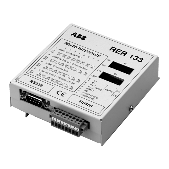
Fig. 5.-2 Dimensions of the RER 133 Bus Connection Module 5.1. Module configuration The attributes for the RER 133 can be set through the two DIP switches on the front of the module. The DIP switches are labeled S1 and S2. Switch S1 Usage... -
Page 10: Configuration Examples
Bus Connection RER 133 1MRS755163 Module Technical Description 5.2. Configuration examples A050319 Fig. 5.2.-1 4-wire, terminated, 19200 bits/s, pull-up and pull-down active A050320 Fig. 5.2.-2 4-wire, no termination, 9600 bits/s A050321 Fig. 5.2.-3 2-wire, terminated, 19200 bits/s, pull-up and pull-down active A050322 Fig. -
Page 11: Interfaces
Fig. 6.-1 Pin usage table for the 9-pin D-type connector (X1) The RS-485 interface of the RER 133 module is shown in Fig. 6.-2. The connector (X2) is an 8-pin Weidmüller terminal block. If GND (pin 5) is used, then it is required for all other nodes to be isolated as well. - Page 12 Bus Connection RER 133 1MRS755163 Module Technical Description The EIA RS-485 Specification labels the data wires "A" and "B", but many manufacturers label their wires "+" and "-". In our experience, the "+" wire should be connected to the "A" line, and the "-" wire to the "B" line.
-
Page 13: Type Designation And Technical Data
Bus Connection RER 133 1MRS755163 Module Technical Description Type designation and technical data RER 133 Type designation RER133 Ordering number Powered from host device (+15 V DC) Auxiliary power supply ~ 1 W, Peak value ~1,8 W Burden 300...19200 bits/s... - Page 16 ABB Oy Distribution Automation P.O. Box 699 FI-65101 Vaasa FINLAND Tel. +358 10 22 11 Fax. +358 10 224 1094 www.abb.com/substationautomation...