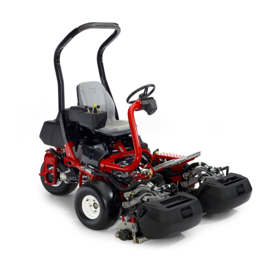
Toro Greensmaster TriFlex 3300 Operator's Manual
Traction unit
Hide thumbs
Also See for Greensmaster TriFlex 3300:
- Manual (334 pages) ,
- Service manual (332 pages) ,
- Operator's manual (52 pages)

Related Manuals for Toro Greensmaster TriFlex 3300


Summary of Contents for Toro Greensmaster TriFlex 3300
- Page 1 Form No. 3436-573 Rev A Greensmaster ® 3300 TriFlex ® Traction Unit Model No. 04510—Serial No. 406000000 and Up *3436-573* A Register at www.Toro.com. Original Instructions (EN)
- Page 2 Replacements may be ordered through help finding a dealer, or to register your product. the engine manufacturer. Whenever you need service, genuine Toro parts, or WARNING additional information, contact an authorized Toro distributor and have the model and serial numbers of CALIFORNIA your product ready.
-
Page 3: Table Of Contents
Contents Safety ............... 4 g000502 Figure 2 General Safety........... 4 Safety and Instructional Decals ......5 Safety-alert symbol Setup ................ 9 1 Installing the Roll Bar ........10 2 Installing the Seat .......... 10 This manual uses 2 words to highlight information. 3 Installing the Steering Wheel......11 Important calls attention to special mechanical 4 Activating and Charging the Battery ....11... -
Page 4: Safety
Safety Drive System Maintenance ........33 Checking the Tire Pressure....... 33 Checking the Torque of the Wheel This machine has been designed in accordance with Nuts .............. 33 EN ISO 5395 and ANSI B71.4-2017 and meets these Adjusting the Transmission for Neutral....33 standards when you complete the setup procedures. -
Page 5: Safety And Instructional Decals
Safety and Instructional Decals Safety decals and instructions are easily visible to the operator and are located near any area of potential danger. Replace any decal that is damaged or missing. decal133-8062 133-8062 decal119-9346 119-9346 1. Press the pedal to unlock. 2. - Page 6 decal131-2046 131-2046 1. Double lights 3. Off 2. Single light decal136-8506 136-8506 1. Warning—read the 4. Tipping hazard—slow the Operator’s Manual; do machine before turning; not operate this machine do not turn at high speeds. unless you are trained. 2. Warning—wear hearing 5.
- Page 7 decal139-6493 139-6493 1. Lower and engage the reels. 8. Reel—mow 2. Raise and disengage the reels. 9. Reel—backlap 3. Mow direction 10. Choke 4. Fast 11. Engine—start 5. Slow 12. Engine—run 6. Neutral 13. Engine—stop 7. Reel—transport...
- Page 8 decal115-8156 115-8156 1. Reel height 3. 8–blade cutting unit 5. 14–blade cutting unit 7. Fast 2. 5–blade cutting unit 4. 11–blade cutting unit 6. Reel speed 8. Slow decal139-2727 139-2727...
-
Page 9: Setup
Grass-basket hook Install the grass-basket hooks. Flange bolts Gauge bar Cutting unit (obtain from your authorized Install the cutting units. Toro distributor) Grass basket Weight Kit (Part No. 119-7129)—sold separately Add rear weight. Three-Wheel-Drive Weight Kit (Part No. 120-5750—sold separately) Warning decal (Part No. -
Page 10: Installing The Roll Bar
Installing the Roll Bar Installing the Seat Parts needed for this procedure: Parts needed for this procedure: Roll bar Seat Bolt (1/2 x 3-3/4 inches) Seat wire harness Flange nut (1/2 inch) Procedure Procedure Note: Mount the seat in the front set of mounting holes to gain an additional 7.6 cm (3 inches) in the Remove the top crate support from the crate. -
Page 11: Installing The Steering Wheel
Locate the open connector on the main wire harness to the right of the seat and connect it to the wire harness that came with the seat. Route the seat wiring harness around the seat Activating and Charging slides, ensuring that it is not pinched when the seat moves, and connect it to the port on the the Battery bottom of the seat. -
Page 12: Installing The Oil Cooler
secure them with the bolts and nuts (Figure Slide the rubber boot over the positive terminal to prevent a possible short from occurring. WARNING Incorrect battery cable routing could damage the tractor and cables, causing sparks. Sparks can cause the battery gasses to explode, resulting in personal injury. -
Page 13: Installing The Grass-Basket Hooks
Installing the Grass-Basket Installing the Cutting Units Hooks Parts needed for this procedure: Gauge bar Parts needed for this procedure: Cutting unit (obtain from your authorized Toro Grass-basket hook distributor) Flange bolts Grass basket Procedure Procedure Install the 6 grass-basket hooks onto the ends of the Prepare the cutting units for installation;... -
Page 14: Installing The Ce Decals
Installing the CE Decals Parts needed for this procedure: Warning decal (Part No. 136-8505) CE mark decal (Part No. 93-7252) g271539 Figure 12 Production year decal 1. Production year decal Procedure If you use this machine in a country that complies to CE standards, perform the following steps after you install the guard kit to the machine: •... -
Page 15: Product Overview
Product Overview g014603 Figure 14 1. Traction pedal—forward 3. Steering-arm-locking pedal 2. Taction pedal—reverse g014674 Figure 13 1. Engine 5. Steering wheel 2. Roll bar 6. Traction pedal 3. Control panel 7. Footrest 4. Seat 8. Cutting units Controls g005105 Traction Pedal Figure 15 The traction pedal... - Page 16 Throttle Lever Functional Control Lever Use the throttle lever (Figure 16) to control the speed The functional control lever (Figure 16) provides 2 of the engine. Move the throttle lever toward the F traction selections plus a N position. You can EUTRAL position to increases the engine speed;...
- Page 17 Hour Meter Backlap Lever The hour meter (Figure 17) indicates the total hours The backlap lever is located under the plastic cover to the machine has operated. It starts to function the left of the seat. Use the backlap lever (Figure whenever you rotate the ignition switch to the O in conjunction with the raise/lower mow control lever...
- Page 18 Seat-Adjusting Lever The seat-adjusting lever is located on the front, left corner of the seat (Figure 21), allowing you to adjust the seat forward and rearward. Note: If you need additional adjustment on the seat, you can remove the 4 nuts securing the seat slide rails to the base and move the seat slide rails to the second set of mounting holes provided.
-
Page 19: Specifications
Authorized Service Dealer or authorized Toro attached and functioning properly. Do not operate distributor or go to www.Toro.com for a list of all the machine unless they are functioning properly. approved attachments and accessories. -
Page 20: Fuel Specification
Fuel Specification filler neck. This space in the tank allows the fuel to expand. Fuel tank capacity: 26.6 L (7 US gallons) Important: Do not fill the fuel tank Recommended Fuel: Unleaded gasoline with an completely full. octane rating of 87 or higher ((R+M)/2 rating method) Install the cap. -
Page 21: Breaking In The Machine
Slope Safety and ensure that the grass baskets are installed on the machine. • Slopes are a major factor related to loss of control • Operate the machine only in good visibility to avoid and rollover accidents, which can result in severe holes or hidden hazards. -
Page 22: Starting The Engine
If fluid leaks continue to appear, contact Note: Inspect the areas beneath the cutting units to your authorized Toro distributor for assistance ensure that they are clear of debris. and, if necessary, replacement parts. Sit on the seat, engage the parking brake,... -
Page 23: Driving The Machine Without Mowing
The safety-interlock system prevents the machine lever to the N position, and engage the EUTRAL from moving unless: parking brake. • The parking brake is disengaged. Start the engine. • You are seated in the operator's seat. Release the parking brake, move the functional control lever to the M position, and rise from •... - Page 24 stopping the machine, raising and lowering the cutting much of the green as possible to minimize units, and turning). the amount of grass left to mow around the outer periphery. Inspect the green for debris, remove the flag from To cut down on operating time and to ease the the cup, and determine the best direction to mow.
-
Page 25: After Operation
Empty the grass baskets of all clippings before you transport the machine to the next green. Note: Heavy wet clippings place an undue strain on the baskets and add unnecessary weight to the machine, which increases the load on the machine systems (e.g., engine, hydraulic system, and brakes). -
Page 26: Hauling The Machine
Towing the Machine pressure does not contaminate and damage the seals and bearings. Do not wash a warm engine or the electrical connections with water. In case of an emergency, you can tow the machine for up to 0.4 km (1/4 mile). After cleaning the machine, do the following: Important: Do not tow the machine faster than 3... -
Page 27: Maintenance
Determine the left and right sides of the machine from the normal operating position. Note: Download a free copy of the electrical or hydraulic schematic by visiting www.Toro.com and searching for your machine from the Manuals link on the home page. -
Page 28: Recommended Maintenance Schedule(S)
Recommended Maintenance Schedule(s) Maintenance Service Maintenance Procedure Interval • Torque the wheel nuts. After the first hour • Torque the wheel nuts. After the first 10 hours • Check the engine speed (at idle and full throttle). After the first 50 hours •... -
Page 29: Daily Maintenance Checklist
Daily Maintenance Checklist Duplicate this page for routine use. Maintenance Check Item For the week of: Mon. Tues. Wed. Thurs. Fri. Sat. Sun. Check the safety-interlock operation. Check the instrument operation Check the leak-detector alarm. Check the brake operation. Check the fuel level. Check the hydraulic-fluid level. -
Page 30: Engine Maintenance
Engine Maintenance Engine Safety • Shut off the engine before checking the oil or adding oil to the crankcase. • Do not change the governor speed or overspeed the engine. Servicing the Air Cleaner Service Interval: Every 50 hours—Service the air-cleaner foam element g005126 Figure 29 (more frequently when operating... -
Page 31: Replacing The Spark Plugs
Remove the oil filter (Figure 31). Apply a light coat of clean oil to the new filter gasket. Screw the filter on by hand until the gasket contacts the filter adapter, then tighten it 3/4 to 1 turn further. Do not overtighten it. Add oil to the crankcase;... -
Page 32: Fuel System Maintenance
Fuel System Electrical System Maintenance Maintenance Electrical System Safety Replacing the Fuel Filter • Disconnect the battery before repairing the Service Interval: Every 500 hours (sooner if the fuel machine. Disconnect the negative terminal first flow is restricted). and the positive last. Connect the positive terminal first and the negative last. -
Page 33: Locating The Fuses
Drive System WARNING Incorrect battery cable routing could damage Maintenance the tractor and cables, causing sparks. Sparks can cause the battery gasses to explode, resulting in personal injury. Checking the Tire Pressure • Always disconnect the negative (black) Service Interval: Before each use or daily battery cable before disconnecting the positive (red) cable. -
Page 34: Adjusting The Transport Speed
Important: Ensure that the tension on the eccentric is at the maximum adjustment, cable is not excessive or you will reduce the contact your authorized Toro distributor cable life. or refer to the Service Manual for further adjustment. Reducing the Transport Speed... -
Page 35: Adjusting The Mowing Speed
Adjusting the Mowing Brake Maintenance Speed Burnishing the Brakes The mow speed is set to 3.8 mph at the factory. Service Interval: Yearly You can adjust the forward moving speed from 0 to 8 km/h (0 to 5 mph). Firmly apply the brakes and drive the machine at mowing speed until the brakes are hot, as indicated Loosen the jam nut on the trunnion bolt (Figure... -
Page 36: Hydraulic System Maintenance
Toro. Servicing the Hydraulic This fluid is compatible with the elastomers used in Toro hydraulic systems and is suitable for a Fluid wide-range of temperature conditions. This fluid is compatible with conventional mineral oils, but for... - Page 37 Park the machine on a level surface, shut off the engine, engage the parking brake, and remove the key. Fill the replacement filter and lubricate the sealing gasket with the specified hydraulic fluid. At the right side of the machine, align a drain pan under the hydraulic filter (Figure 39).
-
Page 38: Checking The Hydraulic Lines And Hoses
the reservoir with an alternative fluid, change loose fittings, weather deterioration, and chemical the hydraulic fluid. deterioration. Make all necessary repairs before operating. Hydraulic-Fluid Capacity: 25.7 L (6.8 US gallons) Park the machine on a level surface, shut off the engine, engage the parking brake, and remove the key. -
Page 39: Checking The Leak Detector
Checking the Leak Detector The leak detector system is designed to assist in early detection of hydraulic-fluid-system leaks. If the fluid level in the main hydraulic reservoir is lowered by 118 to 177 ml (4 to 6 oz), the float switch in the tank will close. - Page 40 Checking the the machine to stand for 1 to 2 minutes to allow the fluid levels to stabilize. Then start the machine and Leak-Detector-System Operation operate it in a non-sensitive area to confirm that no Move the ignition switch to the O position.
-
Page 41: Cutting Unit Maintenance
Cutting Unit Maintenance Blade Safety A worn or damaged blade or bedknife can break, and a piece could be thrown toward you or bystanders, resulting in serious personal injury or death. • Inspect the blades and bedknives periodically for excessive wear or damage. •... - Page 42 g014609 Figure 46 1. Latch—closed position 3. Latch—open position 2. Suspension-arm bar g014690 Figure 48 g014611 Figure 47 1. Reel motor 3. Cavity 2. Spline shaft 4. Motor-retaining bar 1. Suspension-arm bar 2. Cutting-unit bar Mount a grass basket onto the basket hooks on Close the latches down and around the the suspension arm.
-
Page 43: Checking The Reel-To-Bedknife Contact
Checking the Reel-to-Bedknife Contact Each day before operating the machine, check the reel-to-bedknife contact, regardless if the quality of cut had previously been acceptable. There must be light contact across the full length of the reel and bedknife; refer to the Cutting Unit Operator’s Manual. Backlapping the Reels WARNING Contact with the reels or other moving parts... -
Page 44: Setting The Reel Speed
When finished, return the backlap levers to the (F) position, replace the cover, and ORWARD wash all lapping compound off of the cutting units. Adjust cutting unit reel to bedknife as needed. Move the cutting unit reel speed control to the desired mowing position. Important: If the backlap lever is not returned to the F... -
Page 45: Reel Speed Table
*N/R: Not Recommended Diagnostics System the service-indicator light flashes a number of times, giving you the error code that you or your authorized Toro distributor can use to identify the problem. Diagnosing the Note: You cannot start the engine in diagnostic mode. -
Page 46: Storage
While the engine is still warm, drain the oil from the crankcase. Refill it with fresh oil; refer to For a list of error codes, refer to your authorized Toro Changing the Engine Oil and Filter (page 31). - Page 47 If possible, store the machine in a warm, dry location.
- Page 48 Notes:...
- Page 49 Notes:...
- Page 50 The Toro Company (“Toro”) respects your privacy. When you purchase our products, we may collect certain personal information about you, either directly from you or through your local Toro company or dealer. Toro uses this information to fulfil contractual obligations - such as to register your warranty, process your warranty claim or to contact you in the event of a product recall - and for legitimate business purposes - such as to gauge customer satisfaction, improve our products or provide you with product information which may be of interest.
- Page 51 While the exposure from Toro products may be negligible or well within the “no significant risk” range, out of an abundance of caution, Toro has elected to provide the Prop 65 warnings. Moreover, if Toro does not provide these warnings, it could be sued by the State of California or by private parties seeking to enforce Prop 65 and subject to substantial penalties.
- Page 52 Countries Other than the United States or Canada Customers who have purchased Toro products exported from the United States or Canada should contact their Toro Distributor (Dealer) to obtain guarantee policies for your country, province, or state. If for any reason you are dissatisfied with your Distributor's service or have difficulty obtaining guarantee information, contact your Authorized Toro Service Center.