Table of Contents
Advertisement
Quick Links
Advertisement
Table of Contents

Related Manuals for LG 29FS2RKE


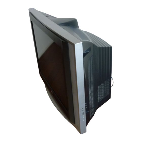
Summary of Contents for LG 29FS2RKE
- Page 1 COLOR TV SERVICE MANUAL CHASSIS : MC-049D MODEL:29FS2RKE/RKQ/RL/RLE/RLX MODEL: 29F2RKE/RKQ/RL/RLE/RLX-TR CAUTION BEFORE SERVICING THE CHASSIS, READ THE SAFETY PRECAUTIONS IN THIS MANUAL.
-
Page 2: Table Of Contents
CONTENTS Contents ........................2 Safety Precautions....................3 Control Descriptions..................4 Specifications......................7 Adjustment Instructions .................8 T rouble Shooting ....................14 Printed circuit board..................18 Block Diagram ......................21 Exploded View....................26 Exploded View Parts List................27 Replacement Parts List .................28 SVC. Sheet........................- 2 -... -
Page 3: Safety Precautions
SAFETY PRECAUTIONS IMPORT ANT SAFETY NOTICE Many electrical and mechanical parts in this chassis have special safety-related characteristics. These parts are identified by the Schematic Diagram and Replacement Parts List. It is essential that these special safety parts should be replaced with the same components as recommended in this manual to prevent X-RADIATION, Shock, Fire, or other Hazards. -
Page 4: Control Descriptions
STOP (Volume Up/Down) adjusts the volume. adjusts menu settings. I/II LIST SLEEP EYE/ 6. VCR BUTTONS (option) control a LG video cassette recorder. Q.VIEW FAVOURITE TEXT 7. SSM (Sound Status Memory) recalls your preferred sound setting. TIME REVEAL MODE 8. I/II (option) - Page 5 15. LIST displays the programme table. 16. EYE/ (option) POWER switches the eye function on or off. MUTE 17. SLEEP sets the sleep timer. 18. Q.VIEW returns to the previously viewed programme. 19. FAVOURITE TV/AV selects a favorite programme. MENU SOUND PICTURE 20.
- Page 6 Front panel ON/OFF ON/OFF Side panel 1. MAIN POWER (ON/OFF) 6. AUDIO/VIDEO IN SOCKETS (AV3) switches the set on or off. Connect the audio/video out sockets of external equipment to these sockets. 2. POWER/STANDBY INDICATOR S-VIDEO/AUDIO IN SOCKETS (S-AV) illuminates brightly when the set is in standby Connect the video out socket of an S-VIDEO mode.
-
Page 7: Specifications
4) Follow each drawing or spec for spec and performance of Test and Inspection Method parts,based upon P/N of B.O.M 1) performance : Follow the Standard of LG TV test 5) Warm up TV set for more than 20min. before the 2) Standards of Etc. requirement measurement. -
Page 8: Adjustment Instructions
(5) The receiver must be operated for about 15 minutes prior ¢‚ to the adjustment. 15 ~ 20mm PURITY Adjustment (6) Signal: Received, the standard color signal.(65dB±1dB uV) LG standard signal means the digital pattern PAL- Let the screen Standard condition. DY Fixing EU(05CH) Operate Heat-Run at least 15 minutes. - Page 9 (5) Open angle of the two tab of 6 pole magnet by isogonic 2. White balance IIC Parameter angle and accord with vertical line of Red/Blue and Green. Program TWBeng_v049(hex) Program TWBeng_v049(hex) Speed Delay (6) Maintain as angle of (5) and rotate the tab to accord with Vcd Slave BCF0 Eprom_Slave...
- Page 10 8. Deflection setting initial data <Table 4> Deflection setting initial data (SERVICE 2) Item Description 29” Adjust or Fix Vert. Linearity Adjust Vert. Amplitude Adjust Recommend S--Correction Vert.Position Adjust Hor. Position Adjust Hor.Width Adjust Trapezoidal Adjust <Fig. 2>PAL Digital pattern (EU05CH) Pin Cushion -130 Adjust...
- Page 11 <Table 6> Picture setting service data2 (SERVICE 3) 10. How to inspect condition of a transmission and reception in FM ITEM DESCRIPTION 29” LPD TRANSMISSION MODEL Internal Brightness for Measurement IBRM White Drive Current Measurement WDRM - FM TRANSMITTER’s efficiency inspections is executed to a finished in a final inspection phase.
- Page 12 11.1. OPTION1 Function 11.3. OPTION3 Function Option Code Function Remark Option Code Function Remark INCH TEXT 200RP(WITHOUT TEXT) 100PR(WITH TEXT) FLOP TXT TOP TXT 29F/ 25F ACMS WITHOUT ACMS FUNCTION 28WF/ 32FW WITH ACMS FUNCTION I II SV NO SAVE DUAL SOUND CONDITION 29N/ 25N SAVE DUAL SOUND CONDITION NON EU...
- Page 13 11.4. OPTION4 Function OPTION CODE FUNCTION REMARK OSD L English Only EU-5EA EU-ETC GREECE EU-ALL PARSI ARAB URDU E+HINDI E+I+M+V E+THAI E+CHINA TXT L English/ French/ Swedish/ Czech/ German/ Spanish/ Italian WEST EU Polish/ French/ Swedish/ Czech/ German/ Slovenian/ Italian/ Romanian EAST EU 1 English/ French/ Swedish/ Turkish/ German/ Spanish/ Italian TURKEY EU...
-
Page 14: Trouble Shooting
TROUBLE SHOOTING RF- STEREO Selected correct system In menu Check the waveform Check / Replace IF 1 of TU101 TU 101 Check the waveform Check The Voltage Check The voltage At pin 4, 5 of IC11 At pin 2, 19, 20, 21, 24 of IIC11 At pin of IC821, IC822, Q807 Check the waveform Check / Replace... - Page 15 NO RASTER CHECK B+ At D829 cathode Normal Abnormal Open Is the voltage at Check each pin voltage of IC11 Fuse of AC line Check / Replace Fuse Check the In/out of Check pin 60 Check the Voltage regulator Of IC11(H - Out) Of C803 (IC821, IC822 Check &...
- Page 16 No Picture / No Sound Is any OSD displayed? Check receiving system in MENU Check IC11 pin71,72,73 & execute Auto - Program. (R,G,B out) Does the auto - Program Operate properly. Store on manual - program MENU Go to Check SMPS Trans Check 1.8V, 3.3V, Check pin40(V out 1) No Sound /...
- Page 17 AV Stereo Select correct system In menu Check the connection Of AV equipment Check the the waveform Check TU101 Tuner At pin16, 17 of IC11 Check the voltage Check the waveform Of pin2, 19, 20, 21,24 of IC11 At pin4, 5, of IC11 Check the signal line of Check waveform SPK-L,R...
-
Page 18: Printed Circuit Board
PRINTED CIRCUIT BOARD MAIN - 18 -... - Page 19 DEGAUSSING HARMONICS LED + PRE-AMP - 19 -...
- Page 20 POWER CONTROL SIDE-A/V - 20 -...
-
Page 21: Block Diagram
BLOCK DIAGRAM - 21 -... - Page 22 <LAYOUT> - 22 -...
- Page 23 - 23 -...
- Page 24 <POWER> - 24 -...
- Page 25 MEMO - 25 -...
-
Page 26: Exploded View
EXPLODED VIEW P1112 - 26 -... -
Page 27: Exploded View Parts List
PWB(PCB) ASSEMBLY,SUB M.I MC049D SY-KIEV CPT BOARD SKD 68719SMH67A PWB(PCB) ASSEMBLY,SUB 29FS2RLQ-TR. AMELLAX CPT BOARD 68719SMK55A PWB(PCB) ASSEMBLY,SUB M.I MC049D 29FS2RKE-TR .KTILLEI CPT B/D[LGEIN_CKD] 68719SML20A PWB(PCB) ASSEMBLY,SUB M.I MC049D 29FS2R . CPT-BOARD LGEMT 68719MM121A PWB(PCB) ASSEMBLY,MAIN 29FS2RLX-TR QDRLLBK SY-KIEV SKD 68719MMV07A PWB(PCB) ASSEMBLY,MAIN M.I MC049D 29FS2RKQ-TR.ATCLLA... -
Page 28: Replacement Parts List
REPLACEMENT PARTS LIST LOCA. NO PART NO DESCRIPTION LOCA. NO PART NO DESCRIPTION Q804 0TR319809AA KTC3198(KTC1815) TP TO92 50V 150MA KTA1274-Y TO-92L TP KEC Q807 0TR127409AB HIC920 0IZZVF0018A STK396-110 DIP 11PIN HYBRID STICK SCAN 0TR102009AB KRC102M,TP(KRC1202),KEC Q808 IC11 692792027AA SOFT WARE, 9.00V 4CC5 CTV MC049D Q901 0TR534309AA 2SC5343Y TP AUK... - Page 29 For Capacitor & Resistors, CC, CX, CK, CN : Ceramic RD : Carbon Film the characters at 2nd and 3rd CQ : Polyester RS : Metal Oxide Film digit in the P/No. means as CE : Electrolytic RN : Metal Film follows;...
- Page 30 For Capacitor & Resistors, CC, CX, CK, CN : Ceramic RD : Carbon Film the characters at 2nd and 3rd CQ : Polyester RS : Metal Oxide Film digit in the P/No. means as CE : Electrolytic RN : Metal Film follows;...
- Page 31 For Capacitor & Resistors, CC, CX, CK, CN : Ceramic RD : Carbon Film the characters at 2nd and 3rd CQ : Polyester RS : Metal Oxide Film digit in the P/No. means as CE : Electrolytic RN : Metal Film follows;...
- Page 32 For Capacitor & Resistors, CC, CX, CK, CN : Ceramic RD : Carbon Film the characters at 2nd and 3rd CQ : Polyester RS : Metal Oxide Film digit in the P/No. means as CE : Electrolytic RN : Metal Film follows;...
- Page 33 For Capacitor & Resistors, CC, CX, CK, CN : Ceramic RD : Carbon Film the characters at 2nd and 3rd CQ : Polyester RS : Metal Oxide Film digit in the P/No. means as CE : Electrolytic RN : Metal Film follows;...
- Page 34 For Capacitor & Resistors, CC, CX, CK, CN : Ceramic RD : Carbon Film the characters at 2nd and 3rd CQ : Polyester RS : Metal Oxide Film digit in the P/No. means as CE : Electrolytic RN : Metal Film follows;...
- Page 35 P/NO : 38549D0015A - (1/1) 2005.11.10...
-
Page 36: Svc. Sheet
SVC. SHEET : 38549D0015A-S... - Page 37 Dec., 2005 P/NO : 38289S0018A Printed in Korea...