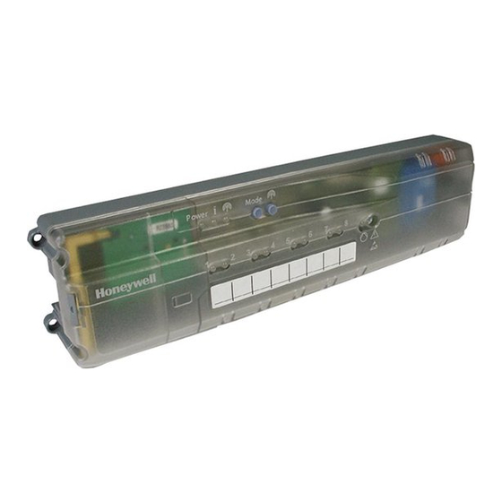
Honeywell HCE 80 Installation And Operation Manual
Underfloor heating controller
Hide thumbs
Also See for HCE 80:
- Mounting and operation instructions (32 pages) ,
- Mounting and operation manual (94 pages)

Related Manuals for Honeywell HCE 80


Summary of Contents for Honeywell HCE 80
- Page 1 HCE 80/HCE 80R HCC 80/HCC 80R Underfloor Heating Controller Installation and Operation Zoneregelaar Montage en gebruik...
- Page 3 ENGLISH NEDERLANDS...
- Page 4 Fig.2 Fig.1 Fig.3 Mode Power Fig.4 Z4 Z5 Z6 Z7 Z8 HRA80 Panther Swite 7 m m 5.5mm 5.5mm Fig.5 Fig.6 Fig.7...
-
Page 5: Table Of Contents
Boiler feedback............7 Appendix ............. 12 6.3.1. Connecting the boiler feedback via an analog 13.1. Glossary .............. 12 output (only HCE 80/ HCC 80) to external 13.2. Help with problems ..........13 controllers.............. 7 13.3. Technical data ............. 13 6.3.2. -
Page 6: About These Instructions
DANGER Danger to life through electric F Boiler feedback, shock! Analog output (only HCE 80/HCC 80) or Contacts that are open are live. Relay output (only HCE 80R/HCC 80R) G Integrated pump relay ► Unplug the power plug before open- H Thermal actuators ing the housing. -
Page 7: Differences Between The Individual Device Types
• The living area is covered by six temperature zones. The • Boiler feedback additional module HCS 80 is required for this parti- – Analog (only HCE 80/HCC 80) tioning. – Integrated relay with floating contact 42 V AC/DC • The underfloor heating controller controls 8 actuators. -
Page 8: Wall Installation
Installation and configuration 5.1. Wall installation 6.1. Opening the housing Four 4.2 mm holes for installation are located on the under- ► Open the housing as shown in Fig. 2 on the fold-out page. floor heating controller. 6.1.1. Plugging in the expansion module Take the 52 mm installation height of the under- (optional) floor heating controller into account. -
Page 9: Connecting Power Cable
6.3. Boiler feedback 6.3.1. Connecting the boiler feedback via an analog output (only HCE 80/ HCC 80) to external controllers The analog output voltage changes depending on the valve position. ► Strip the connections 5.5 mm (see fold-out page, Fig. 5). -
Page 10: Implementing A Boiler Feedback Via A Wireless Connection (With Hc60Ng/R6660D)
Commissioning With controller MCR 40, the temperature and earth inputs Controller 1 Controller 2 Controller 3 are located at the following terminals: MCR 40 Low-voltage side Pump Earth input Temperature input With controller ZG 252 N, the temperature and earth inputs 6.4.3. -
Page 11: Led Indicators On Underfloor Heating Controller
Assigning zones and allocating room names (teach-in) 7.2. LED indicators on underfloor heat- The underfloor heating controller switches back to normal mode automatically after 60 seconds. ing controller You can also exit the installation mode by press- The LEDs on the underfloor heating controller indicate the ing the Mode button. -
Page 12: Allocating Hometronic Manager Hcm 200D
Assigning zones and allocating room names (teach-in) The underfloor heating controller is in installation mode Information about the parameter settings of the and waits for the signal from the setpoint adjuster. CM67z can be found in the corresponding oper- ating instructions. In order to assign the setpoint adjuster to a dif- ►... -
Page 13: Time Program For Cooling Function
Checking the configuration 8.4. Time program for cooling function The assignment of the room name or the time program to the temperature zone is cancelled. If the cooling function was activated (see "Cooling function", Page 9), a separate time program for heating and cooling 8.7. -
Page 14: Displaying Faults
Displaying faults 10. Displaying faults ► Remove the holder with the fuse (Steps 1 to 3). If the LED lights up, a fault exists in at least one tempera- ► Replace the fuse (4) by a new ture zone. one. The colours of the zone LEDs 1...8 provide information on ►... -
Page 15: Help With Problems
Appendix 13.2. Help with problems 13.3. Technical data Input/Output voltage 230 V AC, 50 Hz Problem Cause/Solution Power consumption Max. 1750 VA with connected pump Power LED does Mains voltage not connected. (max. 6 A) not light up when ► Check voltage of electrical outlet. the power is Pump relay Switching contact 230 V AC, max. -
Page 16: Zoning Plan (Sample)
Appendix 13.5. Zoning plan (sample) Zone Actuator Setpoint ad- Room name juster (location) (type, location) Heating *Cooling Heating *Cooling Heating *Cooling Heating *Cooling Heating *Cooling Heating *Cooling Heating *Cooling Heating *Cooling • Cooling optional 13.6. WEEE directive 2002/96/EC Waste Electrical and Electronic Equipment directive ►... -
Page 17: Brief Instructions
HCE 80/HCC 80/HCE 80R/HCC 80R Controls actuators; communicates with setpoint adjusters and room temperature sensors F Boiler feedback, Analog output (only HCE 80/HCC 80) or Relay output (only HCE 80R/HCC 80R) G Integrated pump relay H Thermal actuators External antenna HCE 80/HCE 80R... - Page 18 Appendix Function Press button Status LED Zone LED Exit mode • Automatically after Send test signal Light up red when the test signal Keep LED flashes green is sent Mode pressed 10 min for 4 seconds • Press other button •...
- Page 19 13.3. Technische gegevens.......... 28 6.3.1. Ketelsturing via analoge uitgang (uitsluitend 13.4. Toestel- en functiedefinities conform EN 60730- HCE 80/HCC 80) op externe regelaars 1 ................28 aansluiten ............21 13.5. Zoneschema (sjabloon) ........28 6.3.2. Ketelsturing tot stand brengen via draadloze 13.6.
-
Page 20: De Gebruiksaanwijzing
D Hometronic Manager HCM 200D centraal bedieningstoestel van het (Z1...Z8) Aansluitklem voor zone 1...8 woningautomatiseringssysteem Fig. 5 I/O-aansluitklem E Zoneregelaar HCE 80/HCC 80/HCE 80R/HCC 80R Fig. 6 Aansluitklem voor zone 1...8 stuurt thermische motoren aan; communiceert met Fig. 7 Aansluitklem voor voedingsspanning pomp... -
Page 21: Verschillen Tussen De Afzonderlijke Toesteltypen
• Geïntegreerd pomprelais Uitleg bij dit voorbeeld: • Ketelsturing • De woning is verdeeld in 6 temperatuurzones. Voor deze analoog (uitsluitend HCE 80/HCC 80) – indeling is uitbreidingsmodule HCS 80 nodig. geïntegreerd relais met potentiaalvrij contact –... -
Page 22: Wandmontage
Installatie en configuratie 5.1. Wandmontage 6.1. Behuizing openen Voor de wandmontage zijn op de zoneregelaar 4 Open de behuizing zoals afgebeeld in Fig. 2 op de ► bevestigingsgaten met een diameter van 4,2 mm uitklappagina. aangebracht. 6.1.1. Uitbreidingsmodule plaatsen Houd rekening met de montagehoogte van (optioneel) 52 mm van de zoneregelaar! Wanneer de De uitbreidingsmodule HCS 80 verhoogt het mogelijke... -
Page 23: Netkabel Aansluiten
► Montage Demontage 6.3. Ketelsturing 6.3.1. Ketelsturing via analoge uitgang (uitsluitend HCE 80/HCC 80) op externe regelaars aansluiten De analoge uitgangsspanning is afhankelijk van de stand van de zoneventielen. 6.2.3. Thermische motoren aansluiten Strip de aansluitingen over 5,5 mm ►... -
Page 24: Ketelsturing Tot Stand Brengen Via Draadloze Verbinding (Met Hc60Ng/R6660D)
Inbedrijfstelling Regelaar 1 Regelaar 2 Regelaar 3 MCR 40 Laagspanningszijde Pomp Massa-ingang TW-ingang Bij regelaar ZG 252 N liggen TW- en massa-ingang op de volgende klemmen: ZG 252 N 6.4.3. Externe antenne installeren Er kunnen maximaal drie zoneregelaars op een antenne worden aangesloten. -
Page 25: Inbedrijfstelling Zoneregelaar
Zones toewijzen en zonenamen toekennen (Teach-in) 7.1.1. Inbedrijfstelling zoneregelaar 7.5. Koelfunctie Wanneer de zoneregelaar als koelregelaar wordt gebruikt, Schakel de bedrijfsspanning in. ► moet u deze functie bij de installatie eenmalig vrijgeven. De LED voor de netspanning (POWER) brandt. 7.5.1. Koelfunctie vrijgeven 7.2. -
Page 26: Temperatuurvoeler Met Instelknop Hcw 82
Zones toewijzen en zonenamen toekennen (Teach-in) Druk de installatieknop zo vaak in, tot de LED dooft. Per temperatuurzone kan slechts één ► temperatuurvoeler worden toegewezen. De zoneregelaar draait weer in normaal bedrijf. Wanneer een temperatuurvoeler HCF 82 en een temperatuurvoeler met instelknop HCW 82 Wanneer de installatieknop langer dan 4 min. -
Page 27: Teach-In Tijdprogramma Cm67Z (Zone 1)
Zones toewijzen en zonenamen toekennen (Teach-in) 8.3.2. Teach-in tijdprogramma CM67z 8.5. Relaismodule voor aansturing van (zone 1) de warmtebron toewijzen Al naar gelang de warmtevraag van de geïnstalleerde Druk opnieuw de installatieknop op de zoneregelaar in. ► ruimtes stuurt de relaismodule HC60NG/R6660D de stand De LED van zone 1 knippert groen. -
Page 28: Configuratie Controleren
Configuratie controleren 9. Configuratie controleren 10. Storingen weergeven Wanneer de LED brandt, is er in minimaal één Druk de installatieknop kort in. ► temperatuurzone een storing opgetreden. De LED knippert geel. De kleuren van de zone-LED's 1...8 geven informatie over De zoneregelaar bevindt zich in de toestelweergave. -
Page 29: Zekering Vervangen
In een van de temperatuurzones is een De LED brandt na storing opgetreden (zie pagina 26 ). inbedrijfstelling Hometronic Woningautomatiseringssysteem van continu rood. Honeywell. RF communicatie controleren. ► Hometronic Centraal bedieningstoestel van het Controleer de antenneaansluiting. ► Manager Hometronic systeem. -
Page 30: Technische Gegevens
Appendix 13.3. Technische gegevens 13.5. Zoneschema (sjabloon) Zone Thermische Afstands- Ruimtenaam In-/uitgangsspanning 230 VAC, 50 Hz motor regelaar (plaats) Opgenomen vermogen max. 1750 VA met aangesloten (type, plaats) pomp (max. 6 A) Verwarmen Pomprelais Schakelcontact 230 VAC, max. 6 A (niet potentiaalvrij) ;... -
Page 31: Verkorte Gebruiksaanwijzing
D Hometronic Manager HCM 200D centraal bedieningstoestel van het woningautomatiseringssysteem E Zoneregelaar HCE 80/HCC 80/HCE 80R/HCC 80R stuurt thermische motoren aan; communiceert met afstandsregelaars en temperatuurvoelers F Ketelsturing, analoge uitgang (uitsluitend HCE 80/HCC 80) of relaisuitgang (uitsluitend HCE 80R/HCC 80R) G Geïntegreerd pomprelais... - Page 32 Appendix Functie Knop indrukken Status-LED Zone-LED Modus verlaten • Automatisch na 10 min. Testsignaal zenden knippert groen Branden continu rood tijdens het en Mode zenden van het testsignaal 4 sec. ingedrukt houden • Andere knop indrukken • Automatisch na 60 sec. Ketelmodus Mode >...
- Page 34 Manufactured for and on behalf of the Environmental and Combustion Controls Division of Honeywell Technologies Sàrl, Ecublens, Route du Bois 37, Switzerland by its Authorized Representative: Honeywell GmbH Böblinger Straße 17 71101 Schönaich, Germany Tel.: (++49) (0) 7031 637 01 Fax: (++49) (0) 7031 637 493 http://europe.hbc.honeywell.com...