Table of Contents
Advertisement
Quick Links
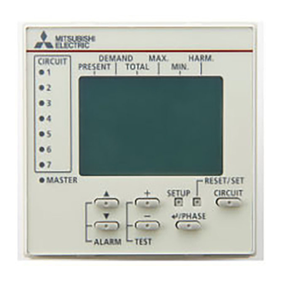
DISPLAY UNIT for (Energy Measuring Unit)
Model:EMU4-D65
Instruction manual (Simplified edition)
● Be sure to read this instruction manual and this equipment detail manual before use.
● After reading on, you keep it in a safe place where you can be seen at any time, please read when needed.
● Please send this instruction manual to the end user.
1. Feature
The monitoring of measured data at Mitsubishi Energy Measuring Unit is possible.
Easily viewable by backlight and dot matrix LCD display.
Multiple circuit monitoring is possible using only one unit.
It is possible to switch the display language (Japanese / English) in the setting.
2. Confirmation of contents of package
Each unit comes with the following accessories. Check for missing ones.
Main Body x1
3. Precautions concerning working environment and conditions
3.1 Working environment and working conditions
This equipment, based on the assumption that it is used in the pollution degree 2 (Note 1) environment.If it is used in other degree of contamination, please
do the protection on the device side to be incorporated.Measurement categories for measuring circuit for this equipment is CATⅢ (Note 1).
The overvoltage category of the auxiliary power supply circuit (MA, MB) is CATⅢ (Note 1).Do not use the unit in any of the following places. Doing so may
cause malfunction or reduction in service life.
⋅ Place where the ambient temperature exceeds the working temperature range( −5°C - +55°C)
⋅ Place where the humidity exceeds the humidity range (30% - 85%RH) or condensation occurs
⋅ Place with much dust, corrosive gas, salt or oily smoke
⋅ Place where the unit may be exposed to rain or drops of water
⋅ Place where metallic particles or inductive substances are dispersed
This equipment is the open type equipment. (Electric shock protection of the instrument was designed to perform housed in another apparatus equipment)
Please use are housed in a control panel etc. Always. For notes on when to adapt the equipment that you have configured in this equipment to the EMC
Directive, please refer to the "user's manual (Details)".
Note 1:For a definition of pollution degree and the measurement categories, please refer to the EN61010-1 / 2010.
3.2 Preparation before using
• An installation place should keep the working environment and working conditions.
• The protection sheet for the crack prevention is put on the display part. Before use this product, remove the protection
sheet. It is not unusual, although a LCD display part may light up by generating of static electricity in case it removes.
After a while, it disappears by natural electric discharge.
• Following setup is need before using EMU4-D65.
The one always in one system is the Master set, Other display unit of, please to Slave configuration.
(The wrong setting and it does not work)
3.3 Installation and connection
• Before installing and connecting the unit, read the instruction manual without fail. For safety, the unit shall be installed and connected by experts in electrical work.
• When threading and wiring, take utmost care that cuttings and wire pieces do not enter the unit.
Caution
• Connect the wires carefully checking the wiring diagram. Improper wiring can cause unit failure, fire and electric shock.
• Perform wiring work in a dead state. Do not wire the unit in a live state. Doing so can cause electric shock, ground fault, unit failure and fire.
3.4 Precautions for Use
• This unit cannot be used for deal and proof of electric energy measurement stipulated in Measurement Act.
• EMU4-PX4 and EMU4-AX4 is supported with later version 2.00. For information about how to determine the version, please refer to "user's manual (Details)"
• Use this unit within the ratings specified in this manual. If it is used outside the ratings, it may cause not only malfunction or failure but also fire burnout.
• Do not disassemble or modify this unit. It may cause failure, malfunction, injury or fire.
Caution
• Do not touch the live part such as connection terminal. It may cause electric shock, electric burn injury or burnout of the device. If any exposed conductor is found, stop the operation
immediately, and take an appropriate action such as isolation protection.
3.5 Maintenance Precautions
• Use a soft dry cloth to clean off dirt of the unit surface. Do not let a chemical cloth remain on the surface for an extended period of time nor wipe the surface with thinner or
benzene.
• Check for the following items to use this unit properly for long time.
(1) Daily maintenance
(a) No damage on this unit
(2) Periodical maintenance (Once every 6 months to 1 year)
• No looseness with installation and wire connection
Do periodical maintenance under the electric outage condition. Failure to do so may cause electric shock, failure of the unit or a fire. Tighten the terminal regularly to prevent a fire. In case a
Caution
display unit is attached to a sensor unit, get off the display unit during maintaining or tightening terminals.
3.6 Storage Precautions
To store this unit, turn off the power and remove wires, and put it in a plastic bag.
For long-time storage, avoid the following places. Failure to follow the instruction may cause a failure and reduced life of the unit.
• Places the Ambient temperature exceeds the range -10°C - +60°C.
• Places the Relative humidity exceeds the range 30% - 85% or places with dewfall.
• Dust, corrosive gas, saline and oil smoke exist.
• Places the average daily temperature exceeds 35°C.
3.7 Disposal Precautions
When disposing of this unit, treat it as industrial waste.
3.8 About packaging materials and this manual
For reduction of environment load, packaging materials are produced with cardboard.
Connection cable x1
(Simplified edition) x1
(b) No abnormality with LED
Instruction manual
⋅ Place where the daily mean temperature exceeds 35°C
⋅ Place with much vibration or impact
⋅ Place exposed to direct sunlight
⋅ Place with strong electromagnetic field or much foreign noise
⋅ Place where the altitude is over 2000m
(c) No abnormal noise, smell or heat
• Vibration and impact exceed the specifications.
• Places exposed to rain, water drop or direct sunlight.
• Places metal fragments or conductive substance are flying.
- 1 -
This product is the optional dedicated
product
only
Measuring
EcoMonitorPro) and Mitsubishi Measuring
Unit for MDU Breakers (MDU2). It can not
be used for other purpose.
Switching board
Installation screw x2
for
Mitsubishi
Energy
Unit
(EcoMonitorPlus,
Please use after removing the
protection sheet.
.
Advertisement
Table of Contents

Related Manuals for Mitsubishi Electric EMU4-D65


Summary of Contents for Mitsubishi Electric EMU4-D65
- Page 1 It is not unusual, although a LCD display part may light up by generating of static electricity in case it removes. After a while, it disappears by natural electric discharge. • Following setup is need before using EMU4-D65. The one always in one system is the Master set, Other display unit of, please to Slave configuration.
-
Page 2: Part Names And Functions
Display unit Display unit (1) Remove the trunking MODEL EMU4-HM1-MB MODEL EMU4-VA2 MODEL EMU4-VA2 MODEL EMU4-VA2 EMU4-D65 EMU4-D65 EMU4-D65 connector To the socket “DISPLAY” LOG. SD CARD To the socket To the socket To the socket SD C. To the socket BAT. - Page 3 7. Operations of Instrument (in the case of the model to connect the EMU4-**) 7.1 Operation mode There are following modes of operation. This device is used to switch the operation mode depending on the application. Such as the following, View of measurement value, Setting for rating, display, clock, Setup for the condition of monitoring, Reset the Max./Min, Data and alarm data, Preset the value of Wh and varh.
-
Page 4: Disp.mode
Screen Operation Note 4 Setup the primary current All models except for EMU4-LG1-MB, EMU4-PX4 and EMU4-AX4 ( ) 4-1. (1) In 4-1, Push the ▲ or ▼ key, and move the cursor to the “3 A rate”. [Sensor]:Direct⇔5A⇔ [Measure] (2) Push the / Phase key. - Page 5 Screen Operation Note 7(1) Setup the demand time EMU4-BM1-MB EMU4-HM1-MB EMU4-A2 EMU4-VA2 ( 、 、 、 ) 7(1)-1. [Demand]:0sec⇔10sec⇔20sec⇔30sec⇔40sec⇔50sec⇔ (1) In 7-1, push the ▲ or ▼ key, and move the cursor to the “6 Demand”. [Measure] 1min ⇔ 2min ⇔ 3min ⇔ 4min ⇔ 5min ⇔ 6min ⇔ 7min ⇔ (2)...
- Page 6 Screen Operation Note 11-3. High SENS mode (1) Push the ▲ ▼ + - key, and change the Ior difference converted [DIF.Ior]:0.00~100.00mA [DIF.Ior] reference value. (2) Push the / Phase key,and confirm the setting value. 0.00 mA Low SENS mode (3)...
- Page 7 Screen Operation Note 2 Setup input EMU4-HM1-MB, EMU4-PX4 ( ) 2-1. (1) In 2-1, Push the ▲ or ▼ key , and move the cursor to the ”1 Input”. [I/O] (2) Push the / Phase key. Input (3) 2-2 will be displayed. 2 OP.Time 3 Output 2-2.
-
Page 8: Outline Drawing
8. Operations of Instrument (in the case of the model to connect the EMU2-** and MDU2-**) For setting operation in the case of connect the EMU2-** and MDU2-**, please refer to the “user’s manual (Details)”. 9. Outline drawing ■ Display Unit main body (EMU4-D65) ■Display unit connection cable 1000 ▲...