Panasonic AFPX-COM5 User Manual
Hide thumbs
Also See for AFPX-COM5:
- Specifications (25 pages) ,
- Specifications (25 pages) ,
- Upgrade procedure (3 pages)
Advertisement
Quick Links
:
Additions
FP-X User's Manual
Only the supplement added in the manual is mentioned. For other information, refer to the manual No.
ARCT1F409E-2.
-New Release(Release date:Feb.2007)
1.2 Unit Types
1.2.4 Add-on Cassettes (Communication Cassettes/Application Cassettes)
Name
FP-X communication
cassette
Chapter 2 Specifications and Functions of Control Unit
With the AFPX-COM5, for some units, the "limitations on number of simultaneous input on points" in the input
specifications and the "limitations on number of simultaneous output on points" in the output specifications are
changed. Confirm the units with the table below before use.
Relevant control units
limitations on number of simultaneous
input on points
AFPX-C14R
AFPX-C14RD
AFPX-C30RD
Buy: www.ValinOnline.com | Phone 844-385-3099 | Email: CustomerService@valin.com
Specifications
3-wire 1-channel
Ethernet, RS232C
Related manual:ARCT1F409E-2
100V AC:30mA or less
200V AC:20mA or less
24V DC:75mA or less
limitations on number of simultaneous
output on points
February.2007
Weight
Product No.
25g
AFPX-COM5
1
Advertisement

Related Manuals for Panasonic AFPX-COM5


Summary of Contents for Panasonic AFPX-COM5
-
Page 1: Chapter 2 Specifications And Functions Of Control Unit
Chapter 2 Specifications and Functions of Control Unit With the AFPX-COM5, for some units, the “limitations on number of simultaneous input on points” in the input specifications and the “limitations on number of simultaneous output on points” in the output specifications are changed. - Page 2 limitations on number of simultaneous limitations on number of simultaneous input on points output on points AFPX-C60RD APFX-C30TD AFPX-C60T AFPX-C30PD No change AFPX-C60P No change Buy: www.ValinOnline.com | Phone 844-385-3099 | Email: CustomerService@valin.com...
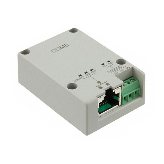
- Page 3 This communication cassette is a 1-channel unit with an Ethernet interface and an isolated three-wire RS232C port. The Ethernet is converted to the RS232C with the AFPX-COM5, and connected to the FP-X. This communication cassette functions as a converter between Ethernet and RS232C.
- Page 4 Check if the communication format and baud rate for the COM1 port of the FP-X matches the configuration setting of the AFPX-COM5. 16.1 Dimensions - When Installing Add-on Cassette Note) The AFPX-COM5 is 5 mm taller than other communication cassettes. Buy: www.ValinOnline.com | Phone 844-385-3099 | Email: CustomerService@valin.com...
-
Page 5: Ethernet Communication (Afpx-Com5)
7.7 Ethernet Communication (AFPX-COM5) 7.7.1 AFPX-COM5 Overview The communication cassette AFPX-COM5 has an Ethernet interface at the COM1 port and a 3-wire RS232C interface at the COM2 port. The Ethernet at the COM1 port supports the computer link and general-purpose serial communication, and the RS232C at the COM2 port supports the computer link, general-purpose serial communication and MODBUS RTU. - Page 6 The setting is saved in the AFPX-COM5. IP address setting Item Description Default Unit name Unit name for Communication cassette AFPX-COM5 can be specified. FPX_ET IP address of Communication cassette AFPX-COM5 IP address 192.168.1.5 Set an IP address other than 0.0.0.0 and 255.255.255.255. Subnet mask Netmask of Communication cassette AFPX-COM5 255.255.255.0...
- Page 7 Communication mode: Computer link (Ethernet) The supplement is described below to perform Ethernet communication by the computer link. Reference: <7.3.1 Computer Link> Overview • Communication is conducted between a computer and a PLC using Ethernet by the computer link. • Remote programming and monitoring is possible via LAN line by using a programming tool such as FPWIN GR.
- Page 8 Communication format Stop bit 1 bit Terminator Header STX not exist Note1) No.415 Baud rate 115200 bps/9600 bps Note1) Set the baud rate to match the baud rate (COM1 port) of the AFPX-COM5. Buy: www.ValinOnline.com | Phone 844-385-3099 | Email: CustomerService@valin.com...
- Page 9 Start the Configurator WD. Search the AFPX-COM5. Select the AFPX-COM5 from the search result, and set an IP address to connect wit a computer. After that, search again. Select the AFPX-COM5, and select [Edit] → [Communication Setting] in the menu, or right-click to select [Communication Setting].
- Page 10 This setting enables the 1:1 communication between the FP-X and a computer using the computer link (Ethernet). System register setting of FP-X (specified using FPWIN GR) Dialog box of PLC system register setting COM1 port setting (AFPX-COM5) Setting item Setting value No.410 Unit number No.412...
- Page 11 Setting of Communication cassette AFPX-COM5 (specified using Configurator WD) IP address setting Item Default Unit name FPX_ET IP address 192.168.1.5 Subnet mask 255.255.255.0 Default gateway 192.168.1.1 Communication setting Item Default Communication mode Computer link Action mode Server mode Baud rate (COM1) 9600 bps Source port No.
- Page 12 It is no problem if the unit number of the PLC overlaps with other PLCs. 1:N Communication setting (Computer link (Ethernet)) The settings for the FP-X system register and communication cassette AFPX-COM5 are the same as the settings for the connection (computer link (Ethernet)) by a 1:1 communication.
- Page 13 (Ethernet). Number of connection is one. • Select either the client mode or server mode. • In case of the client mode, connection is established by the AFPX-COM5 for a predetermined IP address after turning on the power supply of the FP-X.
- Page 14 Start the Configurator WD. Search the AFPX-COM5. Select the AFPX-COM5 from the search result, and set an IP address to connect wit a computer. After that, search again. Select the AFPX-COM5, and select [Edit] → [Communication Setting] in the menu, or right-click to select [Communication Setting].
- Page 15 COM1 port of the FP-X. Note: Initializing Ethernet takes approx. 5 seconds on the AFPX-COM5 after turning on the power supply. Until it finishes, data cannot be sent or received. For Ethernet communication, programming is necessary to start communication after a lapse of 5 seconds after the power activation.
-
Page 16: Initialization Procedure
6. Install the AFPX-COM5 on the FP-X, and turn on the power supply. Note) The Ethernet communication setting (including the IP address) cannot be changed when the switch at the back of the AFPX-COM5 is on. Always turn it off after initialization. Setting for initialization...