Table of Contents
Advertisement
Quick Links
Advertisement
Table of Contents

Related Manuals for Toro Groundsmaster 360 31223


Summary of Contents for Toro Groundsmaster 360 31223
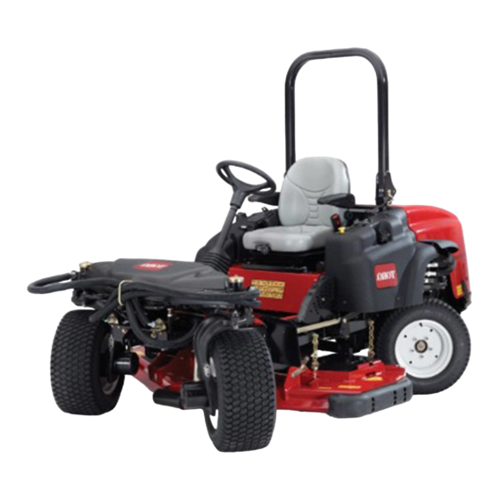
- Page 1 Form No. 3424-897 Rev A Groundsmaster ® 360 4-Wheel Drive Multi-Purpose Machine Model No. 31223—Serial No. 403330001 and Up Model No. 31230—Serial No. 403330001 and Up Model No. 31236—Serial No. 403330001 and Up *3424-897* A Register at www.Toro.com. Original Instructions (EN)
- Page 2 Declaration of Conformity (DOC) sheet. on safe operating practices, including safety tips and training materials, go to www.Toro.com. Genuine Toro spark arresters are approved by the USDA Forestry Service. You may contact Toro directly at www.Toro.com for product safety and operation training materials,...
-
Page 3: Table Of Contents
Contents Changing the Engine Oil and Filter....38 Adjusting the Throttle........39 Fuel System Maintenance ........39 Safety ............... 4 Servicing the Water Separator ......39 General Safety ........... 4 Bleeding the Fuel System ......... 40 Safety and Instructional Decals ......4 Bleeding Air from the Fuel Injectors.... -
Page 4: Safety
Safety • Do not operate the machine without all guards and other safety protective devices in place and working on the machine. This machine has been designed in accordance with • Keep clear of any discharge opening. Keep EN ISO 5395:2013 and ANSI B71.4-2017. bystanders and pets a safe distance away from the machine. - Page 5 decal117-3233 117-3233 1. Read the Operator's Manual for information on fuses. 2. 4-wheel steer solenoid—7.5 A 3. PTO enable, 4-wheel-steer lamp, deck lift, deck float—7.5 A 4. Glow indicator, fuel-run solenoid, diagnostic light, start—7.5 5. Headlights, deck actuator, power takeoff—10 A 6.
- Page 6 decal120-0250 120-0250 1. Slow-moving vehicle decal117-3277 117-3277 1. Lower decks 6. Two-wheel steering 2. Raise decks 7. Four-wheel steering 3. Engine—stop 8. Fast 4. Engine—run 9. Continuous variable setting decal120-0273 120-0273 5. Engine—start 10. Slow decal117-4766 117-4766 1. Cutting/dismemberment hazard, fan—stay away from moving parts;...
- Page 7 decal125-7427 125–7427 1. Raise/Lower decks 5. Engine—run 2. 2-wheel steering 6. Engine—start 3. 4-wheel steering 7. Fast 4. Engine—stop 8. Slow decal125-9688 125-9688 Model with Cab Only 1. Windshield wipers—off 3. Windshield wipers—on 2. Windshield wipers 4. Spray windshield washer fluid decal130-0594 130-0594...
- Page 8 decal130-0611 130-0611 Model with Cab Only 1. Warning—1) Remove the pin; 2) Raise the doors; 3) Exit the cab decaloemmarkt Manufacturer's Mark decal132-6552 132-6552 1. Indicates that the blade is identified as a part from the 2-Wheel Drive with ROPS and 4-Wheel Drive with ROPS original machine manufacturer.
- Page 9 decalbatterysymbols Battery Symbols Some or all of these symbols are on your battery. 1. Explosion hazard 6. Keep bystanders a safe distance away from the battery. 2. No fire, open flame, or 7. Wear eye protection; smoking explosive gases can cause blindness and other injuries.
- Page 10 decal117-3273 117-3273 1. Warning—read the Operator's Manual. 6. Thrown object hazard—keep bystanders a safe distance away from the machine. 2. Warning—do not operate this machine unless you are trained. 7. Warning—engage the parking brake, shut off the engine, and remove the key from the key switch before leaving the machine.
- Page 11 decal132-3378 132-3378 Model with Cab Only 1. Raise/Lower decks 5. Engine—run 2. 2-wheel steering 6. Engine—start 3. 4-wheel steering 7. Fast 4. Engine—stop 8. Slow...
-
Page 12: Setup
Setup Loose Parts Use the chart below to verify that all parts have been shipped. Procedure Description Qty. PTO driveshaft Bolt (5/16 x 1-3/4 inches) Install the PTO driveshaft to a optional deck or QAS. Locknut (5/16 inch) Roll pin (3/16 x 1-1/2 inches) Retainer pin Use the hardware to install the optional Grease fitting... -
Page 13: Using The Optional Mower-Deck-Mounting Hardware
Torque the locknuts to 20 to 25 N∙m (175 to 225 in-lb). Lubricate the grease fittings on the PTO driveshaft. After you connect the other end of the driveshaft to the attachment gearbox shaft, connect the wire-harness connector to the PTO solenoid-valve-coil connector (Figure g018339... -
Page 14: Checking The Tire Pressure
Product Overview Controls Become familiar with all the controls before you start the engine and operate the machine. Traction Pedal The traction pedal (Figure 6) controls the forward and reverse operation. Press the top of the pedal to move forward and the bottom to move rearward. The ground speed depends on how far you press the pedal. -
Page 15: Parking Brake
you, press the foot pedal and release it when the steering wheel reaches the desired operating position. Parking Brake To engage the parking brake, push down on the brake pedal and press the top forward to latch it (Figure 6). To disengage the parking brake, press the brake pedal until the parking-brake latch retracts. -
Page 16: Diagnostic Light
Glow-Plug-Indicator Light (Orange Light) The glow-plug-indicator light (Figure 7) turns on when you turn the ignition switch to the O position. It remains on for 6 seconds. When the light turns off, you can start the engine. Charge-Indicator Light The charge-indicator light illuminates when the charging-system circuit malfunctions (Figure Oil-Pressure Warning Light... -
Page 17: Cab Controls
Use the Diagnostic ACE display tool and the overlay position. Pull out and down on the latch to close and to help verify and correct electrical functions of the secure the windshield. machine. Contact your authorized Toro distributor for assistance. Cab Controls Model with Cab Only... -
Page 18: Specifications
Specifications Note: Specifications and design are subject to change without notice. g197702 Figure 12 Description Figure 12 Dimension or Weight reference Height with roll bar up 201 cm (79 inches) Height with roll bar down 137 cm (54 inches) Height with cab 225 cm (88-1/2 inches) Overall length 276 cm (108-1/2 inches) -
Page 19: Attachments/Accessories
Authorized Service Dealer or authorized Toro • Check that operator-presence controls, safety distributor or go to www.Toro.com for a list of all switches, and shields are attached and functioning approved attachments and accessories. properly. Do not operate the machine unless they are functioning properly. -
Page 20: Adding Fuel
Do not use fuel additives. convert to biodiesel blends. • For more information on biodiesel, contact your Petroleum Diesel authorized Toro distributor. Cetane rating: 40 or higher Fuel Tank Capacity Sulfur content: Low sulfur (<500 ppm) or ultra-low sulfur (<15 ppm) 51 L (13.5 US gallons) -
Page 21: Checking The Engine-Oil Level
Service Interval: Before each use or daily System If the safety system does not operate as described below, have an authorized Toro distributor repair the Before you start the engine and use the machine, system immediately. check the cooling system; refer to... -
Page 22: Raising And Lowering The Seat
To adjust the back of the seat, turn the knob, located under the right-side armrest, in either direction to provide the best comfort (Figure 14). Changing the Lumbar Support You can adjust the back of the seat to provide a customized lumbar support for your lower back. -
Page 23: During Operation
• Use accessories, attachments, and replacement • Use your full attention while operating the parts approved by The Toro® Company only. machine. Do not engage in any activity that causes distractions; otherwise, injury or property Rollover Protection System damage may occur. - Page 24 • A cab installed by Toro is a roll bar. or the edge caves in. Establish a safety area between the machine and any hazard. • Always wear your seat belt. • Identify hazards at the base of the slope.
-
Page 25: Starting The Engine
g014175 Figure 19 1. Power-takeoff switch 3. Glow-plug light (PTO) 2. Ignition switch 4. Throttle lever Move the throttle lever midway between the and S positions (Figure 19). g014172 Figure 18 Turn the ignition key clockwise to the R 1. Pin 3. -
Page 26: Shutting Off The Engine
Leave the throttle midway between the S Engage the parking brake whenever you leave the and F positions until the engine and the machine and remove the key. hydraulic system warm up. Important: Selecting the Steering When you start the engine for the first time, change the engine oil, or Mode overhaul the engine, transmission, or wheel... -
Page 27: Operating The Mower Deck Or Attachment
Engaging the Power Takeoff (PTO) green light stops flashing and remains off. When the switch light is continuously off, the machine is in the The power-takeoff (PTO) switch starts and stops the 4-wheel-steering mode. mower blades and some powered attachments. Note: If you turn the steering wheel too briskly, If the engine is cold, allow the engine to warm... -
Page 28: Operating Tips
Alternating Mowing Direction • If a blade is damaged or worn, replace it immediately with a genuine Toro replacement Alternate mowing direction to avoid making ruts in the blade. Refer to the cutting unit Operator’s Manual turf over time. This also helps the disperse clippings, for instructions to replace the blade. -
Page 29: After Operation
Changing to Machine Operation After Operation Rotate each bypass valve clockwise 1 turn and hand tighten them (Figure 25). After Operation Safety Note: Do not overtighten the bypass valves. • Clean grass and debris from the cutting units, Torque the valves approximately 8 N∙m (71 in-lb) mufflers, and engine compartment to help prevent as shown in Figure... -
Page 30: Locating The Tie-Down Points
Locating the Tie-Down Points There are tie downs located at the front and rear sides of the machine (Figure 26). Note: Use properly-rated DOT-approved straps in 4 corners to tie down the machine. • 2 on the front of the operator's platform •... -
Page 31: Maintenance
Determine the left and right sides of the machine from the normal operating position. Download a free copy of the electrical or hydraulic schematic by visiting www.Toro.com and searching for your machine from the Manuals link on the home page. - Page 32 Maintenance Service Maintenance Procedure Interval • Service the air cleaner. (Service the air cleaner earlier if the air-cleaner indicator shows red. Service it more frequently in extremely dirty or dusty conditions.) Every 400 hours • Replace the fuel-filter canister. • Check the fuel lines and connections. •...
-
Page 33: Daily Maintenance Checklist
Daily Maintenance Checklist Duplicate this page for routine use. For the week of: Maintenance Check Item Monday Tuesday Wednesday Thursday Friday Saturday Sunday Check the safety-interlock operation. Check the brake operation. Check the engine-oil level. Check the cooling-system-fluid level. Drain the water/fuel separator. -
Page 34: Pre-Maintenance Procedures
Notation for Areas of Concern Inspection performed by: Item Date Information Pre-Maintenance Procedures CAUTION If you leave the key in the key switch, someone could accidently start the engine and seriously injure you or other bystanders. Remove the key from the key switch before you do any maintenance. -
Page 35: Lubrication
Lubrication The machine has grease fittings that you must lubricate regularly with No. 2 lithium grease. Lubricate the grease fittings immediately after every washing, regardless of interval specified. Greasing the Bearings and Wipe the grease fittings clean so that foreign Bushings matter cannot be forced into the bearing or bushing... - Page 36 Note: To access the grease fittings for the migration through both the upper and lower king-pin rear-steering linkage, remove the storage bushings. You should see grease purging out of both compartment. the top and the bottom of the axle casting/bushing assembly areas of all 4 kingpin assemblies (Figure Note:...
-
Page 37: Engine Maintenance
Preferred oil: SAE 15W-40 (above 0°F) • Alternate oil: SAE 10W-30 or 5W-30 (all temperatures) Toro Premium Engine Oil is available from your authorized Toro distributor in either 15W-40 or 10W-30 viscosity grades. See the parts catalog for part g014183 numbers. -
Page 38: Crankcase Oil Capacity
Changing the Engine Oil If the engine oil level is above the Full mark, change the engine oil. and Filter The best time to check the engine oil is when the engine is cool before it has been started for the day. Service Interval: After the first 50 hours If it has already been run, allow the oil to drain back Every 150 hours... -
Page 39: Adjusting The Throttle
Adjusting the Throttle Fuel System Maintenance Move the throttle lever forward to the front of the control panel slot and then move it back approximately 3 mm (1/8 inch) into the F idle Note: Refer to Fuel Specification (page 20) for the position. -
Page 40: Bleeding The Fuel System
g003993 Figure 35 1. Bleed screw Turn the key in the ignition switch to the O position. The electric fuel pump will begin operation, thereby forcing air out around the air bleed screw. Leave the key in the O position until a solid stream of fuel flows out around the screw. -
Page 41: Cleaning The Fuel Tank
Electrical System Maintenance Electrical System Safety • Disconnect the battery before repairing the machine. Disconnect the negative terminal first and the positive last. Connect the positive terminal first and the negative last. • Charge the battery in an open, well-ventilated area, away from sparks and flames. -
Page 42: Checking The Fuses
Use the Diagnostic ACE display tool and overlay to help verify and correct electrical functions of the machine. Contact your Toro Distributor for assistance. Checking the Interlock g014186 Switches Figure 37 1. - Page 43 CAUTION If safety interlock switches are disconnected or damaged, the machine could operate unexpectedly, causing personal injury. • Do not tamper with the interlock switches. • Check the operation of the interlock switches daily and replace any damaged switches before operating the machine. Verifying the Interlock Switch Function g004140...
- Page 44 If each output switch is in the correct position and functioning correctly but the output LEDs are not correctly illuminated, this indicates an ECM problem. If this occurs, contact your Toro Distributor for assistance. Important: Do not leave the Diagnostic ACE display connected to the machine.
-
Page 45: Drive System Maintenance
Drive System On a paved or dirt surface, turn the steering wheel to the left or right and continue turning until Maintenance all 4 wheels have stopped turning. Automatic synchronization of the wheel alignment should occur. Checking the Tire Pressure Important: Doing this procedure on turf can result in turf damage directly under each of... -
Page 46: Cooling System Maintenance
Cooling System Install the expansion-tank cap. Maintenance Cooling System Safety • Swallowing engine coolant can cause poisoning; keep out of reach from children and pets. • Discharge of hot, pressurized coolant or touching a hot radiator and surrounding parts can cause severe burns. -
Page 47: Brake Maintenance
Brake Maintenance step from the front of the radiator, again from the fan side. After you have thoroughly cleaned the radiator, Adjusting the Brakes remove any debris from the channel at the radiator base and around the frame. Adjust the service brakes when there is more than 25 Clean the engine compartment and the brake mm (1 inch) of free travel of the brake pedal, or when linkage. -
Page 48: Belt Maintenance
Belt Maintenance Checking the Alternator Belt Service Interval: Every 100 hours After the first 10 hours Open the hood and secure the prop rod. Check the tension of the alternator belt by pressing it (Figure 47) midway between the alternator and the crankshaft pulleys with 10 kg (22 lb) of force. -
Page 49: Controls System Maintenance
Controls System Maintenance Adjusting the Traction Drive for Neutral Note: If the machine has recently had the hydraulic fluid changed or the traction motors or hoses replaced, work out any air trapped in the system prior to performing this procedure. To do this, operate the machine in forward and reverse for a few minutes and then replenish the oil as required. -
Page 50: Hydraulic System Maintenance
Toro Premium Transmission/Hydraulic Tractor and hold it there. Fluid (Available in 19 L (5 gallon) pails or 208 L (55 gallon) drums. See the Parts Catalog or your Toro Note: Maintain only light pressure on the pedal Distributor for part numbers). -
Page 51: Changing The Hydraulic Fluid And Filter
Important: Do not engage the PTO. Place a large pan under the hydraulic reservoir and transmission case and remove the plugs, Raise the deck to extend the lift cylinders, shut draining all of the hydraulic fluid (Figure 51). off the engine, and remove the key. Remove the hydraulic-filler cap (Figure 50) from... -
Page 52: Cab Maintenance
Cab Maintenance Cleaning the Cab Important: Use care around the cab seals and lights (Figure 52). If you are using a pressure washer, keep the washer wand at least 0.6 m (2 ft) away from the machine. Do not use the pressure washer directly on the cab seals and lights or under the rear overhang. -
Page 53: Cleaning The Air-Conditioning Coil
Cleaning the Air-Conditioning Coil Service Interval: Every 50 hours Clean the air-conditioning coil more frequently in extremely dusty or dirty conditions. Perform the pre-maintenance procedure; refer Preparing the Machine for Maintenance (page 34). Lift the 4 tabs on the air-conditioning screen (Figure 56) and remove the screen from the top of the cab. -
Page 54: Cleaning
Cleaning Clean the screen, air-conditioning duct, fans, and fan panel using low-pressure air no greater than 276 kPa (40 psi). Waste Disposal Important: Do not use water to clean the condenser because moisture on the Engine oil, batteries, hydraulic fluid, and engine components attracts dirt and dust, which coolant are pollutants. -
Page 55: Storage
Coat the cable terminals and battery posts Preparing the Engine with Grafo 112X skin-over grease (Toro Part No. 505-47) or petroleum jelly to prevent Drain the engine oil from the oil pan and install corrosion. - Page 56 Notes:...
- Page 57 Notes:...
- Page 58 The Toro Company (“Toro”) respects your privacy. When you purchase our products, we may collect certain personal information about you, either directly from you or through your local Toro company or dealer. Toro uses this information to fulfil contractual obligations - such as to register your warranty, process your warranty claim or to contact you in the event of a product recall - and for legitimate business purposes - such as to gauge customer satisfaction, improve our products or provide you with product information which may be of interest.
- Page 59 While the exposure from Toro products may be negligible or well within the “no significant risk” range, out of an abundance of caution, Toro has elected to provide the Prop 65 warnings. Moreover, if Toro does not provide these warnings, it could be sued by the State of California or by private parties seeking to enforce Prop 65 and subject to substantial penalties.
- Page 60 Countries Other than the United States or Canada Customers who have purchased Toro products exported from the United States or Canada should contact their Toro Distributor (Dealer) to obtain guarantee policies for your country, province, or state. If for any reason you are dissatisfied with your Distributor's service or have difficulty obtaining guarantee information, contact the Toro importer.