Advertisement
Quick Links
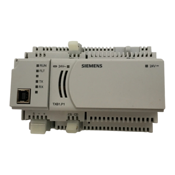
TX-I/O P1 Bus Interface Module
Product Description
The P1 Bus Interface Module (P1 BIM) enables
communication between a P1 Field Level Network
(FLN) and TX-I/O modules. It also provides 14.4 W
(0.6A at 24 Vdc) to power the TX-I/O modules and
external devices. External devices draw power from
the 24 Vdc and ground terminals on the TX-I/O
modules.
Figure 1. P1 Bus Interface Module Example (TXB1.P1-4).
Product Numbers
TXB1.P1
TX-I/O Bus Interface Module, P1
(10 modules, if needed may share
power with TXS1.12F4 TX-I/O
Power Supply)
TXB1.P1-4
TX-I/O Bus Interface Module, P1
(4 modules)
Warning/Caution Notation
WARNING:
Personal injury or property
damage may occur if you do not
follow a procedure as specified.
CAUTION:
Equipment damage or loss of
data may occur if you do not
follow a procedure as specified.
Item Number: 553-140, Rev. GA
Required Tools and Materials
•
Wire stripper/side cutter
•
Small flat blade screwdriver
•
Digital multimeter (DMM)
Expected Installation Time
7 minutes
Prerequisites
CAUTION:
No power wiring is connected to the field
panel controller or other TX-I/O
components at this time.
CAUTION:
The TX-I/O island bus must be mounted
on a DIN rail (1.38" × 0.3" × 0.04"
[35 mm × 7.5 mm × 1 mm]).
•
For energy management installations, NEMA
Type 1 or better enclosure with DIN rails and
source of 24 Vac.
•
For smoke control installations, PX Series
enclosures and service boxes. See the PX
Series Service Box Installation Instructions
(553-131).
•
If mounting in an enclosure:
−
Enclosure is installed.
−
The power source is installed, as
applicable.
−
The power is OFF.
•
All necessary wiring is pulled and terminated
per the layout drawing.
•
Power and communication wiring is terminated
to the removable plugs supplied with the
devices.
Installation Instructions
Document No. 553-140
November 4, 2019
Page 1 of 4
Advertisement

Related Manuals for Siemens P1 BIM


Summary of Contents for Siemens P1 BIM
-
Page 1: Product Description
TX-I/O P1 Bus Interface Module Required Tools and Materials Product Description • Wire stripper/side cutter The P1 Bus Interface Module (P1 BIM) enables • Small flat blade screwdriver communication between a P1 Field Level Network • (FLN) and TX-I/O modules. It also provides 14.4 W Digital multimeter (DMM) (0.6A at 24 Vdc) to power the TX-I/O modules and... - Page 2 General Installation Requirements CAUTION: CAUTION: Only insert or remove the P1 BIM, TX- All devices not isolated by an Island Bus I/O Power Supply, and Bus Connection Expansion module (TXA1.1BE) must be Module when the power is OFF.
- Page 3 DIN rail. Terminate power wiring to the 24 Vac removable plug. If necessary, terminate wires to the communications terminals (CS and CD). The installation is now complete. Connecting Devices to the TX-I/O Island Bus. Siemens Industry, Inc. Page 3 of 4...
- Page 4 Unrestricted Information in this document is based on specifications believed correct at the time of publication. The right is reserved to make changes as design improvements are introduced. APOGEE and Insight are registered trademarks of Siemens Industry, Inc. Other product or company names mentioned herein may be the trademarks of their respective owners.