Table of Contents
Advertisement
Quick Links
Specification
RMS OUTPUT POWER both channel driven simultaneously
10% total harmonic distortion
Input impedance
MUSIC PORT
Output impedance
HEADPHONE
Phone jack
Terminal
Music Port input jack
Terminal
n FM Tuner Section
Frequency range
Sensitivity
S/N 26 dB
Antenna terminals
Preset station
n AM Tuner Section
Frequency range
Sensitivity
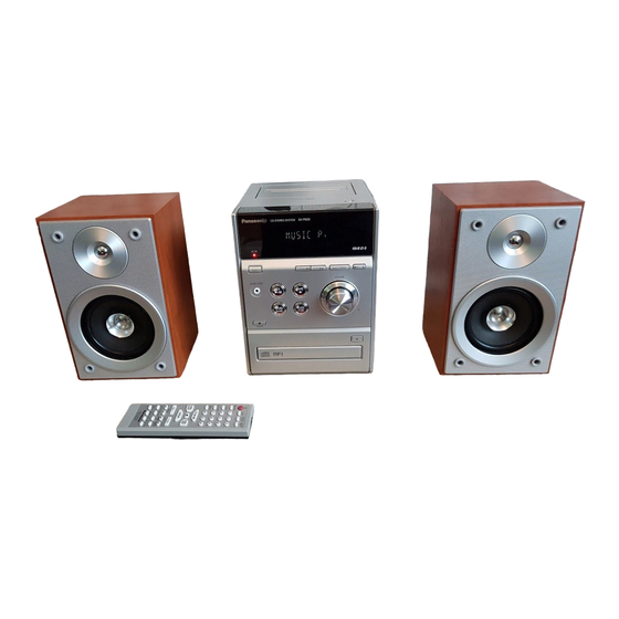
SA-PM33EE
Colour
(S)... Silver Type
S/N 20 dB (at 999 kHz)
20 W per channel (6 Ω)
n Cassette Deck Section
250 mV 12 kΩ
Track system
Heads
16 to 32 Ω
Record/playback
Erasure
Stereo, 3.5 mm
Motor
Recording system
Stereo, 3.5 mm
Erase system
Tape speed
Overall frequency response (+3 dB, -6 dB) at DECK OUT
87.50 to 108.00 MHz
Normal
(50 kHz step)
S/N RATIO
3.8 µV (IHF)
Wow and flutter
1.2 µV
Fast-forward and rewind time
75 Ω (unbalanced)
FM 15 stations
AM 15 stations
n CD Section
Disc played [8 cm or 12 cm]
(1) CD-Audio (CD-DA)
522 to 1629 kHz
(2) CD-R/RW (CD-DA, MP3 formatted disc)
(9 kHz steps)
(3) MP3
520 to 1630 kHz
Sampling frequency
(10 kHz steps)
CD
MP3
ORDER NO. MD0603074C3
CD Stereo System
Approx. 120 seconds with C-60
32 kHz, 44.1 kHz, 48 kHz
© 2006 Matsushita Electric Industrial Co. Ltd.. All
rights
reserved.
Unauthorized
distribution is a violation of law.
1122 µV/m
4-track, 2-channel
Solid permalloy head
Double gap ferrite head
DC servo motor
AC bias 100 kHz
AC erase 100 kHz
4.8 cm/s
35 Hz to 14 kHz
47 dB (A weighted)
0.08% (WRMS)
cassette tape
44.1 kHz
copying
and
Advertisement
Table of Contents

Related Manuals for Panasonic SA-PM33EE


Summary of Contents for Panasonic SA-PM33EE
-
Page 1: Laser Power Class
ORDER NO. MD0603074C3 CD Stereo System SA-PM33EE Colour (S)... Silver Type Specification RMS OUTPUT POWER both channel driven simultaneously S/N 20 dB (at 999 kHz) 1122 µV/m 20 W per channel (6 Ω) 10% total harmonic distortion Input impedance n Cassette Deck Section MUSIC PORT 250 mV 12 kΩ... -
Page 2: Table Of Contents
2. Total harmonic distortion is measured by the digital spectrum Digital filter 8 fs analyzer. D/A converter MASH (1 bit DAC) n System : SC-PM33EE-S Music center: SA-PM33EE-S Speaker: SB-PM33EG-M n General CONTENTS Page Page 1 Safety Precautions 9.12. Disassembly of Main P.C.B. - Page 3 SA-PM33EE 12 Procedure for Checking Operation of Individual Parts of Deck 19.1. CD Servo P.C.B. Mechanism Unit 19.2. Main P.C.B and Tuner Extent P.C.B. 12.1. Operation Check with Cassette Tape 19.3. Panel P.C.B. 12.2. Operation Check without Cassette Tape 19.4. Deck P.C.B, Deck Mechanism P.C.B and Tape Eject 13 Measurement And Adjustments P.C.B.
-
Page 4: Safety Precautions
SA-PM33EE 1 Safety Precautions 1.1. General Guidelines 1. When servicing, observe the original lead dress. If a short circuit is found, replace all parts which have been overheated or damaged by the short circuit. 2. After servicing, ensure that all the protective devices such as insulation barriers, insulation papers shields are properly installed. -
Page 5: Before Repair And Adjustment
SA-PM33EE 1.2. Before Repair and Adjustment Disconnect AC power, discharge Power Supply Capacitors C501, C601, C839, C840, C844, C862, C868, C909, C910, C911 & C923 through a 10Ω, 1W resistor to ground. DO NOT SHORT-CIRCUIT DIRECTLY (with a screwdriver blade, for instance), as this may destroy solid state devices. -
Page 6: Prevention Of Electro Static Discharge (Esd) To
SA-PM33EE 2 Prevention of Electro Static Discharge (ESD) to Electrostatically Sensitive (ES) Devices Some semiconductor (solid state) devices can be damaged easily by electricity. Such components commonly are called Electrostatically Sensitive (ES) Devices. Examples of typical ES devices are integrated circuits and some field-effect transistors and semiconductor “chip”... -
Page 7: Precaution Of Laser Diode
SA-PM33EE 3 Precaution of Laser Diode CAUTION: This unit utilizes a class 1 laser. Invisible laser radiation is emitted from the optical pickup lens. When the unit is turned on: 1. Do not look directly into the pick up lens. -
Page 8: Handling Precautions For Traverse Deck
SA-PM33EE 4 Handling Precautions For Traverse Deck The laser diode in the traverse deck (optical pickup) may break down due to potential difference caused by static electricity of clothes or human body. So, be careful of electrostatic breakdown during repair of the traverse deck (optical pickup). -
Page 9: Handling The Lead-Free Solder
SA-PM33EE 5 Handling the Lead-free Solder 5.1. About lead free solder (PbF) Distinction of PbF P.C.B.: P.C.B.s (manufactured) using lead free solder will have a PbF stamp on the P.C.B. Caution: · Pb free solder has a higher melting point than standard solder; Typically the melting point is 50 - 70°F (30 - 40°C) higher. Please use a high temperature soldering iron. -
Page 10: Accessories
SA-PM33EE 6 Accessories Note : Refer to Packing Materials & Accessories (Section 24) for part number. Remote control AC cord FM indoor antenna AM loop antenna... -
Page 11: Operating Instructions Procedures
SA-PM33EE 7 Operating Instructions Procedures 7.1. Main Unit & Remote Control Operation... -
Page 12: Disc Information
SA-PM33EE 7.2. Disc Information... -
Page 13: Self Diagnosis And Special Mode Setting
SA-PM33EE 8 Self diagnosis and special mode setting This unit is equipped with features of self-diagnostic & special mode setting for checking the functions & reliability. 8.1. Special Mode Table Below is the various special modes for checking:- Item FL Display... - Page 14 SA-PM33EE Item FL Display Key Operation Mode Name Description Front Key Traverse Test determine In doctor Mode: reliability of CD unit. 1. Press [ ], [1], [2] button on remote control. To exit, press button on main unit or remote control.
- Page 15 SA-PM33EE 2. When EEPROM IC is detected and has ROM correction: 3. When EEPROM IC is detected and has ROM correction but NG: Note: Micro-processor firmware version refers to version No. (Eg.MS079_12) for micro-processor IC. It is subject to change which would update accordingly.
- Page 16 SA-PM33EE c) If STOP key is pressed while recording or playing, the operation shall be terminated by stopping TAPE. In this case, the doctor mode is not released. d) DMT is output with the same timing as usual. 8.1.5. TPS Inspection Purpose : To check the TPS.
-
Page 17: Error Code Table
SA-PM33EE 8.2. Error Code Table Self-Diagnosis Function provides information on any problems occuring for the unit and its respective components by displaying error codes. Thesed error code such as U**, H** and F** are stored in memory and held unless it is cleared. - Page 18 SA-PM33EE Error Code Diagnosis Contents Description of error Automatic FL Display Remarks Communication function DTMS For CD unit (For Traverse). Press [ ] on main unit for next between CD servo command, after system LSI and micro-p setting, If SENSE = ´L´...
-
Page 19: Assembling And Disassembling
SA-PM33EE 9 Assembling and Disassembling 9.1. Caution “ATTENTION SERVICER” Some chassis components may be have sharp edges. Be careful when disassembling and servicing. 1. This section describes procedures for checking the operation of the major printed circuit boards and replacing the main components. -
Page 20: Disassembly Flow Chart
SA-PM33EE 9.2. Disassembly flow chart The following chart is the procedure for disassembling the casing and inside parts for internal inspection when carrying out the servicing. To assemble the unit, reverse the steps shown in the chart below. -
Page 21: Main Parts Location Diagram
SA-PM33EE 9.3. Main Parts Location Diagram... -
Page 22: Disassembly Of Side Panel L & R
SA-PM33EE 9.4. Disassembly of Side Panel L & 9.5. Disassembly of Top Cabinet Unit · Disassembly of Side Panel (R) Step 1: Remove 3 screws. Step 1: Remove 5 screws. Step 2: Remove the side panel (R) as arrow shown. -
Page 23: Disassembly Of Deck Mechanism And Tape Eject
SA-PM33EE Step 4: Remove 4 screws. Step 5: Push the lever as arrow shown to open the Step 4: Disconnect FFC cable (CN804). cassette lid. Step 5: Detach connector (CN504A). Step 6: Remove the Deck Mechanism. Step 6: Remove top cabinet unit. -
Page 24: Disassembly Of Panel P.c.b
SA-PM33EE Step 1: Detach connector (CN900B). Step 3: Release 3 claws. Step 4: Remove the Front Panel as arrow shown. 9.9. Disassembly of Panel P.C.B. · Follow the (Step 1) - (Step 4) of Item 9.4. Step 2: Disconnect FFC cable (CN901B). -
Page 25: Disassembly Of Rear Panel
SA-PM33EE Step 1: Detach the connector CN401A and remove the tuner pack as arrow shown. 9.12. Disassembly of Main P.C.B. Step 1: Remove 10 screws. · Follow the (Step 1) - (Step 4) of Item 9.4. Step 2: Remove the Volume Knob. -
Page 26: Disassembly Of Power P.c.b
SA-PM33EE Step 2: Detach connector CP800. Step 3: Detach connector CN803B and CN808B. Step 4: Remove the Main P.C.B. as arrow shown. 9.13. Disassembly of Power P.C.B. Step 2: Remove 1 screw. Step 3: Detach the connector CN501A, CN508A · Follow the (Step 1) - (Step 4) of Item 9.4. -
Page 27: Disassembly Of Speaker Terminal P.c.b
SA-PM33EE 9.15. Disassembly of Transformer P.C.B. · Follow the (Step 1) - (Step 4) of Item 9.4. · Follow the (Step 4) - (Step 6) of Item 9.5. · Follow the (Step 1) - (Step 2) of Item 9.10. · Follow the (Step 1) - (Step 4) of Item 9.13. -
Page 28: Disassembly Of Cassette Lid
SA-PM33EE Step 2: Remove the Cassette Open Spring as Step 1: Remove 4 screws. arrow shown in order. Step 2: Remove the Main P.C.B. support. Step 3: Remove CD Mechanism as arrow shown. 9.17. Disassembly of Cassette Lid · Follow the (Step 1) - (Step 2) of Item 9.4. -
Page 29: Disassembly Of Traverse Unit, Driving Gear, And Cam Gear (Cd Mechanism Unit)
SA-PM33EE Step 4: Remove the Cassette Lid as arrows shown. 9.18. Disassembly of Traverse Unit, Driving Gear, and Cam Gear (CD Mechanism Unit) 9.18.1. Disassembly of the Traverse Unit · Follow the (Step 1) - (Step 4) of Item 9.4. - Page 30 SA-PM33EE...
- Page 31 SA-PM33EE...
-
Page 32: Disassembly Of Optical Pickup (Cd Mechanism Unit)
SA-PM33EE 9.19. Disassembly of Optical Pickup (CD Mechanism Unit) · Follow the (Step 1) - (Step 4) of Item 9.4. · Follow the (Step 4) - (Step 6) of Item 9.5. · Follow the (Step 1) - (Step 4) of Item 9.8. -
Page 33: Disassembly Of Traverse Gear A And Traverse Gear B (Cd Mechanism Unit)
SA-PM33EE · Follow the (Step 1) - (Step 2) of Item 9.10 . · Follow the (Step 1) - (Step 4) of Item 9.12. · Follow the (Step 1) - (Step 3) of Item 9.16. · Follow the (Step 1) - (Step 2) of Item 9.18.1. -
Page 34: Disassembly Of Pinch Roller And Head Block (Deck Mechanism Unit)
SA-PM33EE 9.21. Disassembly of Pinch Roller and Head Block (Deck Mechanism Unit) · Follow the (Step 1) - (Step 6) of Item 9.5. · Follow the (Step 1) - (Step 6) of Item 9.6. 9.22. Disassembly of Motor, Capstan Belt A, Capstan Belt... - Page 35 SA-PM33EE...
-
Page 36: Disassembly Of Deck Mechanism
SA-PM33EE 9.23. Disassembly of Deck Mechanism P.C.B. · Follow the (Step 1) - (Step 6) of Item 9.5. · Follow the (Step 1) - (Step 6) of Item 9.6. · Follow the (Step 1) - (Step 4) of Item 9.21. -
Page 37: Service Fixture And Tools
SA-PM33EE 10 Service Fixture and Tools Service Tools Extension P.C.B. (A) Main P.C.B. - Speaker Terminal P.C.B. RFKZPM33E 11 Service Positions Note: For description of the disassembly procedures, see the Section 9 11.1. Checking and Repairing of Deck, Deck Mechanism, Headphone P.C.B. -
Page 38: Checking And Repairing Of Panel P.c.b
SA-PM33EE 11.2. Checking and Repairing of Panel P.C.B. -
Page 39: Checking And Repairing Of Tuner Pack P.c.b
SA-PM33EE 11.3. Checking and Repairing of Tuner Pack P.C.B. -
Page 40: Checking And Repairing Of Transformer P.c.b
SA-PM33EE 11.4. Checking and Repairing of Transformer P.C.B. -
Page 41: Checking And Repairing Of Main P.c.b
SA-PM33EE 11.5. Checking and Repairing of Main P.C.B. -
Page 42: Checking And Repairing Of Cd Mechanism P.c.b
SA-PM33EE 11.6. Checking and Repairing of CD Mechanism P.C.B. -
Page 43: Checking And Repairing Of Speaker Terminal P.c.b
SA-PM33EE 11.7. Checking and Repairing of Speaker Terminal P.C.B. -
Page 44: Checking And Repairing Of Power P.c.b
SA-PM33EE 11.8. Checking and Repairing of Power P.C.B. -
Page 45: Procedure For Checking Operation Of Individual Parts Of Deck Mechanism Unit
SA-PM33EE 12 Procedure for Checking Operation of Individual Parts of Deck Mechanism Unit 12.1. Operation Check with Cassette Tape 1. Pull up the EJECT lever using a rubber band. (Fig. 6) 2. Supply DC5V to MOTOR. (→ MOTOR rotates.) (Fig. 5) 3. - Page 46 SA-PM33EE Fig. 7...
-
Page 47: Measurement And Adjustments
SA-PM33EE 13 Measurement And Adjustments 13.1. Cassette Deck Section 13.1.1. Requirements · Test tape (QZZCFM) (QZZCWAT) · Normal blank cassette tape (QZZCRA) · Digital frequency counter · Oscilloscope · Electrical voltmeter · Headphone jack output jig (Fig. 8) 13.1.2. Setting of Unit ·... - Page 48 SA-PM33EE Fig. 10 Fig. 11 13.1.5. Bias Voltage Check 1. Connect an electrical voltmeter. (Fig. 12) (Refer to Fig. 9 for location of test points) 2. Set the function to “TAPE” position. 3. Insert a normal blank cassette tape (QZZCRA).
-
Page 49: Voltage Measurement And Waveform Chart
SA-PM33EE 14 Voltage Measurement and Waveform Chart Note: · Indicated voltage values are the standard values for the unit measured by the DC electronic circuit tester (high-impedance) with the chassis taken as standard. Therefore, there may exist some errors in the voltage values, depending on the internal impedance of the DC circuit tester. - Page 50 SA-PM33EE 14.1.2. Main P.C.B. MAIN P.C.B Ref No. IC700 MODE CD PLAY STANDBY Ref No. IC800 MODE CD PLAY STANDBY Ref No. IC800 MODE CD PLAY STANDBY Ref No. IC801 MODE CD PLAY STANDBY Ref No. IC802 MODE CD PLAY STANDBY Ref No.
- Page 51 SA-PM33EE 14.1.3. Panel P.C.B. PANEL P.C.B Ref No. IC900 MODE CD PLAY -22.7 -22.7 -22.7 -20.6 -22.7 -20.6 -22.7 STANDBY -21.2 -21.2 -21.2 -21.2 -21.2 -21.2 -21.2 Ref No. IC900 MODE CD PLAY -22.7 -22.7 -20.6 -20.6 -22.7 -22.7 -22.7 -22.7...
- Page 52 SA-PM33EE 14.1.6. Deck P.C.B. DECK P.C.B Ref No. IC1000 MODE CD PLAY STANDBY -0.1 Ref No. IC1001 MODE CD PLAY STANDBY Ref No. IC1001 MODE CD PLAY STANDBY Ref No. Q1101 Q1201 Q1302 Q1303 Q1304 MODE CD PLAY STANDBY 19.8 Ref No.
-
Page 53: Waveform
SA-PM33EE 14.2. Waveform CN801 PIN 4 CN801 PIN 5 CN801 PIN 6 CN801 PIN 7 CD PLAY CD PLAY CD PLAY CD PLAY 3.4Vp-p (10msec.div) 3.56Vp-p (10msec.div) 3.12Vp-p (10msec.div) 3.84Vp-p (10msec.div) CN801 PIN 8 CN803B PIN 5 IC803 PIN 12... - Page 54 SA-PM33EE IC803 PIN 44 IC7001 PIN 21 CN7001 PIN 24 CN7001 PIN 25 CD PLAY CD PLAY CD PLAY CD PLAY 218mVp-p (25msec.div) 1.82Vp-p (5usec.div) 3.08Vp-p (25usec.div) 3.36Vp-p (10usec.div) CN7001 PIN 49 CN7001 PIN 50 CN7001 PIN 56 CN7001 PIN 59...
-
Page 55: Wiring Connection Diagram
SA-PM33EE 15 Wiring Connection Diagram 16 15 15 . 14 . - Page 56 SA-PM33EE...
-
Page 57: Block Diagram
SA-PM33EE 16 Block Diagram OPTICAL PICKUP PHOTO DETECTOR CD SIGNAL OUTL SEMICONDUCTOR OUTR LASER Q7601 SWITCH TO MAIN BLOCK IC7002 BLKCK BA5948FPE2 BLKCK 4CH DRIVE SPOUT SPOUT VREF NRST NRST IC7001 MN6627954MA LSI IC FOCUS [CH3] LEVEL TRVP COIL SHIFT... - Page 58 SA-PM33EE FILTER (DECK 2) R/P HEAD 4(3) 1(2) 7(8) IC1001 AN7326K JK303 P/B REC AMP IC800 22(1) 21(2) 20(3) 19(4) 16(7) 15(8) AUX INPUT JACK 11(12) C1BB00000732 CD SIGNAL A1(A2) D1(D2) 5(6) RIPPLE REJECTION 9(10) 22(21) LOGIC SWITCH REC AMP (L)
- Page 59 SA-PM33EE SIGNAL LINES : MAIN SIGNAL LINE : CD SIGNAL LINE : TAPE PLAYBACK SIGNAL LINE : FM/AM SIGNAL LINE : TAPE RECORD SIGNAL LINE Note : Signal Lines are applicable to the Left Channel only. ) Indicates Pin No. of Right Channel...
- Page 60 SA-PM33EE...
-
Page 61: Notes Of Schematic Diagram
SA-PM33EE 17 Notes of Schematic Diagram (All schematic diagrams may be modified at any time with the development of new technology) Note : S780 CD Open switch S900 Stop/-Demo switch S901 CD switch S902 Tape switch S903 Tuner/Band switch S904... - Page 62 SA-PM33EE...
-
Page 63: Schematic Diagram
IOVDD2 W7001 DVSS1 SDRCK IC7002 BA5948FPE2 4 CH DRIVE C7234 C7352 C7339 0.018 0.018 C7235 R7336 16V10 W7027 R7339 R7330 5.6K R7335 C7338 C7315 0.056 0.47 R7332 S7201 RESET SW R7323 R7315 3.3K R7331 3.3K R7325 SA-PM33EE CD SERVO CIRCUIT... -
Page 64: Main Circuit And Tuner Extent Circuit
L805 WA52 G0C3R3JA0027 REST_SW LOADING R845 LOADING D806 CD_RST WA53 R841 C837 C838 B0ACCE000003 WA63 REST_SW R827 2.7K 6.3V100 6.3V100 STAT R828 R829 WA51 Q802 Q801, Q802 R830 B1GBCFGG0030 CP800 R831 SWITCH S780 CD_OPEN_SW CD_OPEN_SW OPEN SA-PM33EE MAIN/TUNER EXTENT CIRCUIT... - Page 65 CIRCUIT (CN803A) PCONT_1 PCONT_1 ON SCHEMATIC SYS6V DIAGRAM-7 SYS6V CD_7.5V CD_7.5V C862 C863 PGND PGND 16V10 560P C864 50V47 L811 G0C101JA0027 R888 ASP_CLK ASP_DATA 15 14 13 12 11 10 CN901B SA-PM33EE MAIN CIRCUIT PANEL CIRCUIT (CN901A) ON SCHEMATIC DIAGRAM-4...
-
Page 66: Panel Circuit
VOLUME JOG R412 R212 1.8K 1.8K AUX_RCH C412 C212 4700P 4700P R901 R902 R903 R904 R905 VOL_JOG1 1.2K 1.5K 2.2K 3.3K 4.7K VOL_JOG2 C921 C920 100P 100P VREF+ L204 G0C3R3JA0027 D906 B3AAA0000489 R915 STANDBY LED AUX_LCH SYS6V SA-PM33EE PANEL CIRCUIT... -
Page 67: Deck Circuit, Deck Mechanism Circuit And Tape Eject Circuit
3.3K JW308B Q1316 R1345 2SD09650RA JW308A SWITCH Q1314 Q1315 B1GDCFGH0002 B1ACKD000006 MOTOR SUPPLY SWITCH SWITCH SA-PM33EE DECK / DECK MECHANISM / TAPE EJECT CIRCUIT JW1903 IC971 S1000 TAPE EJECT R972 TAPE EJECT R973 IC971 CIRCUIT CNB13030R2AU DECK MECHANISM PHOTO INTERRUPTOR... -
Page 68: Power Circuit
D0EAMM000038 SYS6V CIRCUIT(CN503A) HALT ON SCHEMATIC Q500 PCONT_1 B1GCCFGA0006 DIAGRAM-7 SYS6V C521 C523 D502 D504 CURRENT LIMITING CD_7.5V 0.01 0.01 PGND C512 C501 35V6800 C522 C524 D501 D505 0.01 0.01 WH505A SA-PM33EE POWER CIRCUIT TRANSFORMER CIRCUIT (CN505B) ON SCHEMATIC DIAGRAM-7... -
Page 69: Transformer Circuit, Headphone Circuit And Speaker Terminal Circuit
0.01 B0AACK000004 (CN504A) ON HP_GND T600 SCHEMATIC JK600 HP_R RTP1H3E002 250V 630mA Q602 DIAGRAM-3 R430 C430 KRC102MTA AC IN FC600 FC601 100K 0.01 R606 230V 50Hz VOLTAGE REGULATOR Z600 ERZV10V511CS L600 G0B371HA0005 SA-PM33EE SPEAKER TERMINAL / TRANSFORMER / HEADPHONE CIRCUIT... - Page 70 SA-PM33EE...
-
Page 71: Printed Circuit Board
SA-PM33EE 19 Printed Circuit Board 19.1. CD Servo P.C.B. CD SERVO P.C.B (REPV0082A) TP51 (RF) C7227 W7014 TP19 C7225 TP14 C7226 W7015 C7204 TP50 C7228 TP17 C7216 C7230 TP18 C7231 TP24 CN7002 W7019 R7221 TP13 C7233 W7006 TP16 C7232 W7007... -
Page 72: Main P.c.b And Tuner Extent P.c.b
SA-PM33EE 19.2. Main P.C.B and Tuner Extent P.C.B. MAIN P.C.B (REPV0089A) TUNER EXTENT P.C.B (REPV0090A) CN10 Q808 Q807 W228 CN504A C851 W107 CN11 C223 C222 TO TUNER PACK Z401 (ENG07811QF) C816 IC804 R750 Q421 R890 W303 IC700 W401 R423 W316... -
Page 73: Panel P.c.b
SA-PM33EE 19.3. Panel P.C.B. PANEL P.C.B (REPV0089A) FL900 C911 C910 34 33 C909 IC900 W322 Z901 D900 W122 SENSOR 11 12 R918 C914 R920 C912 C924 WA60 D906 R915 W120 W242 W239 R911 S909 R912 S908 S904 S905 S906 (REC) -
Page 74: Deck P.c.b, Deck Mechanism P.c.b And Tape Eject P.c.b
SA-PM33EE 19.4. Deck P.C.B, Deck Mechanism P.C.B and Tape Eject P.C.B. DECK P.C.B (REPV0092B) DECK MECHANISM P.C.B (REPX0321H) S973 (CR02) Q1310 Q1309 C1315 CN1303 S972 W1009 W1035 S971 R1331 CS971 C1317 Q1304 (HALF) W1053 (MODE) S975 C1311 Q1303 R973 J150... -
Page 75: Power P.c.b And Speaker Terminal P.c.b
SA-PM33EE 19.5. Power P.C.B and Speaker Terminal P.C.B. POWER P.C.B (REPV0090A) SPEAKER TERMINAL P.C.B (REPV0090A) W168 R515 R514 Q504 CN808A CN803A Q501 L302 W405 1-L- ZJ01 R501 SPEAKER 3-R- R502 W250 R503 2-L+ 4-R+ L300 W400 L303 W255 W402 W143... -
Page 76: Transformer P.c.b And Headphone P.c.b
SA-PM33EE 19.6. Transformer P.C.B and Headphone P.C.B. TRANSFORMER P.C.B (REPV0090A) HEADPHONE P.C.B (REPV0089A) WH504 C604 R607 R606 JK900 Q601 250V 630mA Q603 D610 W150 D608 W210 W151 Q602 L600 Q600 CN900B FC600 FC601 R600 D602 R601 C603 CN505B 0089A 0089A... -
Page 77: Illustration Of Ic's, Transistors And Diodes
SA-PM33EE 20 Illustration of IC's, Transistors and Diodes CNB13030R2AU BA5948FPE2 (28P) C0ABBB000297 (8P) C1BB00000732 (32P) MN6627954MA(100P) C0DBZGC00067 AN7326K (22P) C1BB00000987 (16P) MN101C49GHD(100P) C0HBB0000057(44P) 2SC3940ARA C1AA00000612 AN17831A B1BCCG000002 B1ABGC000005 B1GBCFJJ0044 B1GBCFGH0001 B1ADCF000001 B1GDCFGH0002 B1ABCF000011 B1GDCFJJ0002 B1ABGC000001 B1GBCFNN0038 B1GBCFGG0030 B1GBCFGJ0016 B1AACF000063 B1AAGC000006... -
Page 78: Terminal Function Of Ic's
SA-PM33EE 21 Terminal Function of IC's 21.1. IC7001 (MN6627954MA) IC SERVO PROCESSOR/DIGITAL SIGNAL PROCESSOR/DIGITAL FILTER D/A CONVERTER Pin No. Mark Function Pin No. Mark Function DRAM address signal O/P 11 IREF Reference I/P DRAM address signal O/P 9 PLLF PLL Loop Filter Terminal (Phase... -
Page 79: Ic7002 (Ba5948Fpe2) Ic 4Ch Drive
SA-PM33EE 21.2. IC7002 (BA5948FPE2) IC 4CH Drive Pin No. Mark Function Pin No. Mark Function Motor Driver 92 Input Motor Drive (3) reverse - action output Turntable Motor Drive Signal (“L”:ON) Motor Drive (3) forward - action output Motor Drive (1) Input Motor Drive (4) reverse - action Traverse Motor Drive Signal (“L”:... - Page 80 SA-PM33EE Pin No. Mark Function N.C. No Connection N.C. No Connection N.C. No Connection N.C. No Connection N.C. No Connection No Connection No Connection CRTIMER CR Timer N.C. No Connection S/W RST Switch Reset VREF - D/A Converter Reference GND...
-
Page 81: Troubleshooting Flowchart (Cd Section Circuit)
SA-PM33EE 22 Troubleshooting Flowchart (CD Section Circuit) - Page 82 SA-PM33EE...
-
Page 83: Exploded Views
SA-PM33EE 23 Exploded Views 23.1. Cabinet Parts Location... -
Page 84: Cassette Deck (Raa4402-1S) & Traverse Deck Part Location
SA-PM33EE 23.2. Cassette Deck (RAA4402-1S) & Traverse Deck Part Location... -
Page 85: Packaging
SA-PM33EE 23.3. Packaging... - Page 86 SA-PM33EE...
-
Page 87: Replacement Parts List
SA-PM33EE 24 Replacement Parts List Notes: · Important safety notice: Components identified by mark have special characteristics important for safety. Furthermore, special parts which have purposes of fire-retardent (resistors), high-quality sound (capacitors), low noise (resistors), etc are used. When replacing any of these components, be sure to use only manufacturer’s specified parts shown in the parts list. - Page 88 SA-PM33EE Ref. Part No. Part Name & Description Remarks Ref. Part No. Part Name & Description Remarks REM0120 CAP MOTOR ASS’Y Q221 B1ABGC000001 TRANSISTOR RHD26022-1 MOTOR SCREW Q222 B1ABGC000001 TRANSISTOR XTW2+5LFJ HEAD BLOCK UNIT SCRE Q421 B1ABGC000001 TRANSISTOR XTW26+10SFJ SUB-CHASSIS SCREW...
- Page 89 SA-PM33EE Ref. Part No. Part Name & Description Remarks Ref. Part No. Part Name & Description Remarks D7650 MAZ80560ML DIODE L807 G0A200D00002 RF CHOKE COIL L810 G0C101JA0027 COIL VARIABLE RESISTORS L811 G0C101JA0027 COIL L812 J0JKB0000020 EMI BEAD CORE VR900 EVEJ1CF3024B...
- Page 90 SA-PM33EE Ref. Part No. Part Name & Description Remarks Ref. Part No. Part Name & Description Remarks W7016 ERJ3GEY0R00V CHIP JUMPER R223 ERJ6GEYJ470V 47 1/10W W7017 ERJ3GEY0R00V CHIP JUMPER R224 ERJ3GEYJ102V 1K 1/16W W7018 ERJ3GEY0R00V CHIP JUMPER R225 ERJ6GEYJ470V 47 1/10W...
- Page 91 SA-PM33EE Ref. Part No. Part Name & Description Remarks Ref. Part No. Part Name & Description Remarks R753 D0AF100JA039 10 1/4W R882 ERJ3GEYJ102V 1K 1/16W R755 D0GB472JA041 4.7K 1/16W R883 D0GB103JA007 10K 1/16W R756 D0GB472JA041 4.7K 1/16W R885 D0GB104JA007 100K 1/16W...
- Page 92 SA-PM33EE Ref. Part No. Part Name & Description Remarks Ref. Part No. Part Name & Description Remarks R1342 D0GB473JA041 47K 1/16W C375 F1H1H102A219 1000P 50V R1343 D0GB332JA007 3.3K 1/16W C376 ECQV1H224JL3 0.22 50V R1344 D0GB273JA007 27K 1/16W C401 F1H1H221A748 220P 50V...
- Page 93 SA-PM33EE Ref. Part No. Part Name & Description Remarks Ref. Part No. Part Name & Description Remarks C818 ECJ1VB1H472K 4700P 50V C1122 F1H1H103A219 0.01 50V C819 F1H1C104A041 0.1 16V C1123 ECJ1VB1H271K 270P 50V C820 ECJ1VB1H472K 4700P 50V C1201 ECA1HAK010XB 1 50V...
- Page 94 SA-PM33EE Ref. Part No. Part Name & Description Remarks C7352 ECJ1VB1C183K 0.018 16V C7601 ECEA0JKA330I 33 6.3V C7613 F1H1C104A041 0.1 16V C7614 F2A0J101A198 100P 6.3V C7626 F1H1C104A041 0.1 16V C7670 F1H1C104A041 0.1 16V FLE0603A/J/M/S/P...