Advertisement
Quick Links
z r:.�, a: JS. 4 Jt
INSTRUCTIONS
,#
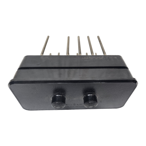
The Type PK -2 test blocks and plugs are used
to test switchboard mounted instruments, meters,
and relays when in an electric circuit or by the use
of
a separate source of power. They are available
in either four or six poles and are back connected.
The contacts have line contact.
'
�
;
�
I"
The PK-2 test blocks and plugs are shipped in
)
i n d i v i d u a l cartons. In the carton. with the test
.. .. .
block, una sse mbled in a s e p a r a t e container, are
sufficient auxiliary contacts for a n y combination
shown in Fig. 8 and 9. Also p a c k e d in the sep-
::!
-
�
..
The block can be mounted on the front surface
of panels 1/8 inch to 2 inches thick or on the rear
surface of a p a n e
(see Fig. 1 and 2}. With both methods of mounting,
the cover and test plug are inserted from the front
of the panel.
Before m o u n t i n g on the pane
Fig.
·
TEST BLOCKS
MOUNTING
1
not more than 1/8 inch thick
I
Mounting on Front of Steel Panel
These instructions do not purport to cover all details or variations in equipment nor to provide for every possible
contingency to be mel in connection with installation, operation or maintenance. Should further information be desired
or should porticular problems arise
be
referred to the G-ral Electric Company.
GENERAL
AND
TYPE PK-2
INTRODUCTION
able of carrying 10 amperes at 250 volts continu
ously. They are not intended to interrupt any cur
rent, but will satisfactorily open the circuit
potential coil and transfer the current coil
struments, meters, or relays.
RECEIVING
arate c o n tai n e r are the n u t s and washers for
the studs; m o u n t i n g screws, washers, and nuts
for m o u n t i n g the test block on steel panels; and
jumpers a n d holding screws for the a uxi l i a r y
contacts.
INSTALLATION
contacts should be assembled according to the com
bination required, as shown in Fig. 8 and 9.
auxiliary contacts. These a r e fastened as shown
by the No.4-48, 5/16 inch round-head screws which
pass through the auxiliary contacts and are threaded
into the inserts in the bottom
iary contact (1, Fig. 3 ), is used to prevent circuit
I,
the auxiliary
interruption when the cover !s removed. This type
Fig.
which
are not covered sufficiently for the purchaser's purposes, the matter should
.
PLUGS
The Type PK-2 test blocks and plugs are cap
Fig. 3 shows a composite assembly of all the
2
Semi-Flush Mounting on 1/8-inch Steel Panel
ELECTRIC
GEH-1023C
of
a
of
in
of
the block. Auxil
I"
Advertisement

Related Manuals for GE PK-2


Summary of Contents for GE PK-2
- Page 1 TYPE PK-2 INTRODUCTION The Type PK -2 test blocks and plugs are used The Type PK-2 test blocks and plugs are cap to test switchboard mounted instruments, meters, able of carrying 10 amperes at 250 volts continu and relays when in an electric circuit or by the use ously.
- Page 2 GEH-1023C Type PK-2 Test Blocks and Plugs of internal connection is shown in F, Fig. With the test block is mounted on an insulation out this connection, loss of revenue is possible due panel, install it on the front of the panel and use the to inte..
- Page 3 Type PK-2 Test Blocks and Phtgs -1023C The p u r p o s e the test plug is to facilitate routine c h e c k testing. They can be permanently connected to any testing equipment. Insertion plug in the test block isolates the auxiliary contacts, when used, and establishes t e s t connections (see Fig.
- Page 4 GEH-1023C Type PK-2 Test Blocks and Plugs :< I" " " � Fig. Back-View Connection of Plug for Testing One Current and One Potential Coil In Circuit . � � + .. Back-View Connection of Test Block for One Fig.