Table of Contents
Advertisement
Quick Links
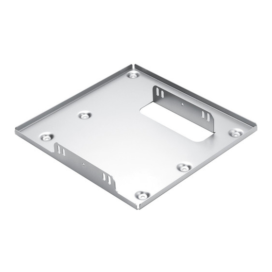
* The figure above shows a combination of this product and the separately sold ET-PKD120S ceiling mount bracket (for low
ceilings).
* Unless specified otherwise, figures in these instructions show a combination with the ceiling mount bracket (for low ceilings).
The installation method is also the same as that of the ceiling mount bracket (for high ceilings).
Thank you for purchasing this Panasonic product.
■ To customers
The "Installation Instructions" is intended for use by installation personnel. Be sure to employ certified personnel to perform
the installation.
After installation, have the installation personnel return these "Installation Instructions" to you, and save it for future use.
When moving or removing the projector, give this manual to the certified personnel and have them perform the procedure.
■ To installation personnel
Read the "Installation Instructions" thoroughly and then perform the operation correctly and safely.
Be sure to read through the section entitled "Read this first!" (page 3) before proceeding with the installation.
After installation, return these "Installation Instructions" to the customer.
Installation Instructions
Projector Mount Bracket
ET-PKD120B
Model No.
TQZJ539-1
Advertisement
Table of Contents

Related Manuals for Panasonic ET-PKD120B


Summary of Contents for Panasonic ET-PKD120B
-
Page 1: Installation Instructions
* The figure above shows a combination of this product and the separately sold ET-PKD120S ceiling mount bracket (for low ceilings). * Unless specified otherwise, figures in these instructions show a combination with the ceiling mount bracket (for low ceilings). The installation method is also the same as that of the ceiling mount bracket (for high ceilings). Thank you for purchasing this Panasonic product. ■ To customers The “Installation Instructions” is intended for use by installation personnel. Be sure to employ certified personnel to perform the installation. After installation, have the installation personnel return these “Installation Instructions” to you, and save it for future use. -
Page 2: Table Of Contents
Contents Read this first! ....................3 Product description ................... 4 Standard installation dimensions ..............5 Installation ......................10 Setting up the screen ......................10 Screws tightening torques ....................10 Installing the bracket to the projector ................10 Attaching the drop prevention kit to the projector ..............11 Specifications .................... -
Page 3: Read This First
Electric shocks may result from contact with any metal objects inside the ceiling. ■ Panasonic disclaims all liability for any accidents or any damage caused by the installation of the ceiling mount bracket using methods that are not described in these Installation Instructions or methods that do not use the parts specified in these Instructions. -
Page 4: Product Description
Product description This is a ceiling mount bracket for installing projectors. ■ Applicable ceiling mount brackets ET-PKD120S / ET-PKD120H ■ Structural components Parts name Form (number of parts) Applications This is used to install the projector Projector mount itself. bracket It also includes a function for adjusting the left/right tilt. -
Page 5: Standard Installation Dimensions
Standard installation dimensions The dimensional relationship between the screen and the projector is shown below. Establish the dimensions after assessing the area possible for installation. ■ Ceiling mount brackets: ET-PKD120S / ET-PKD120H z Projectors: PT-DZ870 / PT-DW830 / PT-DX100 (when using the ceiling mount bracket for low ceilings) Ceiling Projected image (9-13/32") (10-25/32") L (LW/LT) Screen 107.5 <Units: mm (")> (4-7/32") (8-15/32") (when using the ceiling mount bracket for high ceilings) Ceiling Projected image (9-19/32") (10-19/32") L (LW/LT) Screen <Units: mm (")> (Note) This drawing is not in exact scale. -
Page 6: Et-Dle055
Standard installation dimensions (continued) The projection distance can be adjusted using the zoom lens. Check the projected image while making fine adjustments. z I n the case of PT-DZ870 / PT-DW830 / PT-DX100 Unit: m Model number of projection lens L1 size (Approx.) Standard zoom lens 0.043 ET-DLE055 0.028 ET-DLE085 0.084 ET-DLE150 0.045 ET-DLE250 0.045 ET-DLE350 0.051 ET-DLE450 0.095 6 - ENGLISH... - Page 7 Standard installation dimensions (continued) ■ Projection distance according to the projector lens. For the projection distances for projection lenses (optional), refer to the operating instructions [Installation] provided with the projector. Or check the diagonal dimension (m) of your projected image and calculate the projection distance using the following formula. z I n the case of PT-DZ870 Unit: m Model number of Aspect Lens type Projection distance (L) formula projection lens ratio Minimum(LW) L = 1.4906 x SD(m) - 0.0746 16 : 10 Maximum(LT) L = 2.0814 x SD(m) - 0.0725 Minimum(LW) L = 1.5320 x SD(m) - 0.0746 Standard zoom lens — 16 : 9 Maximum(LT) L = 2.1393 x SD(m) - 0.0725 Minimum(LW) L = 1.6874 x SD(m) - 0.0746 4 : 3 Maximum(LT)
- Page 8 Standard installation dimensions (continued) z In the case of PT-DW830 Unit: m Model number of Aspect Lens type Projection distance (L) formula projection lens ratio Minimum(LW) L = 1.5651 x SD(m) - 0.0746 16 : 10 Maximum(LT) L = 2.1855 x SD(m) - 0.0725 Minimum(LW) L = 1.6086 x SD(m) - 0.0746 Standard zoom lens — 16 : 9 Maximum(LT) L = 2.2462 x SD(m) - 0.0725 Minimum(LW) L = 1.7715 x SD(m) - 0.0746 4 : 3 Maximum(LT) L = 2.4736 x SD(m) - 0.0725 16 : 10 — L = 0.7237 x SD(m) - 0.0476 Fixed-focus lens ET-DLE055 16 : 9 — L = 0.7438 x SD(m) - 0.0476 4 : 3 —...
- Page 9 Standard installation dimensions (continued) z In the case of PT-DX100 Unit: m Model number of Aspect Lens type Projection distance (L) formula projection lens ratio Minimum(LW) L = 1.4571 x SD(m) - 0.0746 4 : 3 Maximum(LT) L = 2.0346 x SD(m) - 0.0725 Standard zoom lens — Minimum(LW) L = 1.5875 x SD(m) - 0.0746 16 : 9 Maximum(LT) L = 2.2167 x SD(m) - 0.0725 4 : 3 — L = 0.6738 x SD(m) - 0.0476 Fixed-focus lens ET-DLE055 16 : 9 — L = 0.7340 x SD(m) - 0.0476 Minimum(LW) L = 0.6711 x SD(m) - 0.0471 4 : 3 Maximum(LT) L = 0.8307 x SD(m) - 0.0442 Ultra short focus zoom lens ET-DLE085 Minimum(LW) L = 0.7311 x SD(m) - 0.0471...
-
Page 10: Installation
Installation After checking the height, width, and structure of the installation location while referring to “Standard installation dimensions” on pages 5 to 9, determine the appropriate positions for setting up the screen and installing the projector. Setting up the screen Set up the screen according to the specified method in a position which takes into account the projection distance and angle and the type of screen being used. Screws tightening torques M6 ..4±0.5 N•m M8 ..10±1 N•m z Use a torque screwdriver or torque wrench to tighten screws and bolts to their specified tightening torques. Do not use electric screwdrivers or impact screwdrivers. -
Page 11: Attaching The Drop Prevention Kit To The Projector
Installation(continued) Attaching the drop prevention kit to the projector Attach the wire rope to the projector (sold separately). 1) T urn the adjustment leg (one) counterclockwise to Adjustment leg remove it from the projector. 2) Pass the supplied flat washer (one) and wire rope Adjustment leg through the adjustment leg (one) as illustrated on the left. Flat washer Wire rope 3) Turn the adjustment leg clockwise to secure it to the projector. Note z For installing the ceiling mount brackets (for low and high ceilings) (sold separately) to this bracket as well as attaching the wire rope to the ceiling, refer to the respective installation instructions. -
Page 12: Specifications
Specifications Width: 380 mm (14-31/32"), Height: 56 mm (2-7/32"), External dimensions Depth: 362 mm (14-1/4") Weight Approx. 2.5 (5.5 lbs.) https://panasonic.net/cns/projector/ SS0513AM1047 -PS Printed in Japan...