GE NX-320E Installation Manual
Remote power supply
Hide thumbs
Also See for NX-320E:
- Installation manual (27 pages) ,
- Installation and startup manual (20 pages)
Table of Contents
Advertisement
Quick Links
Download this manual
See also:
Installation Manual
Advertisement
Table of Contents

Related Manuals for GE NX-320E


Summary of Contents for GE NX-320E
- Page 1 NX-320E Remote Power Supply Installation Manual...
- Page 2 Document number/revision: 466-2299A (April 2008). Disclaimer The information in this document is subject to change without notice. GE Security (“GE”) assumes no responsibility for inaccuracies or omissions and specifically disclaims any liabilities, losses, or risks, personal or otherwise, incurred as a consequence, directly or indirectly, of the use or application of any of the contents of this document.
-
Page 3: Table Of Contents
Contents Preface ..................1 Conventions used in this document. - Page 4 NX-320E Remote power Supply Installation Manual...
-
Page 5: Preface
Preface This is the GE NX-320E Remote Power Supply Installation Manual, which describes the following: • how to install the power supply; and • how to program the power supply. There is also information describing how to contact technical support if you have questions or concerns. To use this document effectively, you should have the following minimum qualifications: •... -
Page 6: Product Overview
• UL1023 Household Burglar Alarm Systems • UL1610 Central Station Burglar Alarm Units When the NX-320E is part of a UL commercial fire security system, this unit is compatible with the following: • NX-148E-CF LCD keypad • NX-216E zone expander •... -
Page 7: Installation
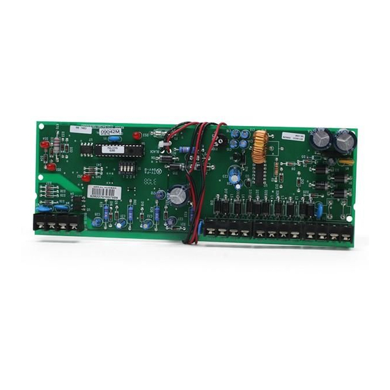
Installation There are several two-holed insertion points inside the enclosure so you can install the module either horizontally or vertically. The insertion points have a large hole and a smaller hole. To mount the board in an enclosure, see Figure 1 and do the following: 1. -
Page 8: Wiring
• Use a 16.5 VAC 50 VA / 120 V, 60 Hz hard-wired transformer (GE Security #T-0002). Do not connect multiple power supply modules in a series (cascaded). The board is wrapped in bubble wrap. Unwrap it so you can orient yourself as you review Figure 2. - Page 9 NX-320E module. Connect to the control panel’s Common terminal. This terminal supplies the common side of the power to the NX-320E module. Connect to the control panel’s Aux power + terminal. This terminal supplies power to the NX-320E module. Accessory terminals DATA Connect the outgoing data-signaling terminal for bus extension.
-
Page 10: Battery
Resistor Battery The battery is not included with the NX-320E. You need the battery for emergency backup.We recommend the Yuasa NP18-12B battery (12 V, 17 Ah). The battery capacity for emergency standby should be at least 24 hours. UL installations must use at least one 17.2 Ah battery for 24 hours of backup. The control panel draws 50 mA standby power. -
Page 11: Addressing
To install the battery, connect the red and black wires to your battery (Figure 4). Figure 4. Battery connection Red wire Black wire 12 volt battery not included Addressing Use the DIP switches to set the module address (84 to 91). Table 4 shows the address settings. Use DIP switch 4 to set the tamper feature: On = enabled, Off = disabled. -
Page 12: Leds
LEDs. Table 5. LED connections Board ID Description LED 1 Flashes when data is transmitted from the NX-320E. LED 2 Flashes when data is transmitted into the NX-320E. LED 3 Flashes during normal operation. LED 4 Glows dimly when connected to the NetworX panel. -
Page 13: Programming
Programming You can use an LED keypad or LCD keypad to program the module. Using an LED keypad To program the module with an LED keypad, do the following: 1. Enter *, 8. All of the function key LEDs will begin to flash. 2. -
Page 14: Programming Data
NX-320E Remote Power Supply Installation Manual Programming data When you program data, you set numerical data or feature selection data. Numerical data. Use the numeric keys of the system keypad with a number from 0 to 255. The system uses a binary process, so to view the data, look at the LEDs for zones 1 through 8 and see which ones are illuminated. -
Page 15: Programming Locations
Programming locations Location 0 - event and time for output A. This location has two segments of numerical data. To program the event and time set the following: • Segment 1. Select the event that triggers Output A. See Table 6 for events you can trigger. •... - Page 16 NX-320E Remote Power Supply Installation Manual Location 1 - special features for output A. This location has two segments of feature selection data to program special features for output A (see Table 7) Table 7. Special features for output Number...
- Page 17 Location 8 - codes 1 to 10, output enable. This location has 10 segments of feature selection data. When you activate outputs with a user code (event #30), you can use Location 8 to restrict certain codes from activating certain outputs. Segment 1 corresponds to user 1; Segment 10 corresponds to user 10. The LEDs correspond to outputs A to C (see Table 8)..
- Page 18 NX-320E Remote Power Supply Installation Manual Location 16 - codes 81 to 90, output enable. This location has 10 segments of feature selection data. When you activate outputs with a user code (event #30), you can use Location 16 to restrict certain codes from activating certain outputs.
-
Page 19: Programming Worksheets
Programming worksheets Use Table 10 to program Locations 1 to 7. Use the Data column to enter your programming information. Table 10. Worksheet for Locations 0 to 7 Location Description Default Data Location 0 - event and time for output A on page 11 0, 10 Location 1 - special features for output A... - Page 20 NX-320E Remote Power Supply Installation Manual Table 10. Worksheet for Locations 0 to 7 (continued) Location Description Default Data Location 7 - special features for the bell output on page 12 Segment 1 3, 5 1. On if timed in minutes; Off if timed in seconds.
- Page 21 Use Table 11 to program Locations 8 to 17. Circle the numbers to indicate your programming information. Table 11. Worksheet for Locations 8 to 17 Location Description Location 8 - codes 1 to 10, output enable on page 13 User Output #A Output #B Output #C...
- Page 22 NX-320E Remote Power Supply Installation Manual Table 11. Worksheet for Locations 8 to 17 (continued) Location Description Location 14 - codes 61 to 70, output enable on page 13 User Output #A Output #B Output #C Location 15 - codes 71 to 80, output enable...
-
Page 23: Specifications
Specifications Dimensions 2.0 × 4.0 in. Current draw AC input 120 V 60 Hz, 650 mA Standby 10 mA VA Transformer 16.5 VAC 50 VA Auxiliary power Limited to 2.0 A Battery 51 Ah for 24 hours of battery backup 5 to 17 Ah in parallel Operating temperature 32 to 120°F (0 to 49°C) Shipping weight... -
Page 24: Contacting Us
Application. Select the appropriate product category for the contact information or use the menu to select a location outside the US. Many GE documents are provided in English only as PDFs. To read these documents, you will need Adobe Reader, which you can download free from Adobe’s website at www.adobe.com.