Haier AB25S2SC1FA Service Manual
R32
Hide thumbs
Also See for AB25S2SC1FA:
- Operation manual and installation manual (26 pages) ,
- Service manual (257 pages) ,
- Operation manual and installation manual (26 pages)
Table of Contents
Advertisement
Advertisement
Table of Contents

Related Manuals for Haier AB25S2SC1FA


Summary of Contents for Haier AB25S2SC1FA
- Page 1 service manual SYJS-04-2017 REV.A Edition: 2017-04...
-
Page 2: Table Of Contents
CONTENTS Part 1 General Information ............................1 1. Indoor/outdoor unit models..........................2 2. Feature .................................3 Part 2 Indoor Units ..............................5 1. Specification ................................6 2. Dimension ................................12 3. Wiring diagram ..............................14 4. Air velocity and temperature distribution .......................17 5. Installation .................................21 Part 3 Outdoor Units ...............................42 1. -
Page 3: Part 1 General Information
Part 1 General Information 1. Indoor/outdoor unit models..........................2 2. Feature .................................3... -
Page 4: Indoor/Outdoor Unit Models
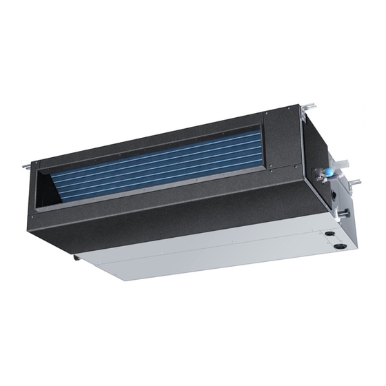
Indoor/outdoor unit models Indoor unit models Compact cassette Low ESP duct AB25S2SC1FA AD25S2SS1FA AB35S2SC1FA AD35S2SS1FA Medium ESP duct AD50S2SM1FA AD71S2SM1FA Outdoor unit models 3U52S2SG1FA 1U71S2SG1FA 3U68S2SG1FA 4U70S2SH1FA 4U85S2SH1FA... -
Page 5: Feature
2. Feature Appearance New valve cover design Compared with the current 1:3 valve cover , we design the new valve cover , which is more slim in the appearance; Cover length Cover length 72.5mm 60mm Current R410a 1:3 New R32 1:3 Installation Less screws to open valve cover In the installation course , installer need to take down the valve cover , then to do wiring and piping , next is the... - Page 6 Easy to carry Left & right two handles are easy for two people carry the units; handl e handl e handl e handl e Easy start up & maintenance * “88” screen show compressor frequency or failure code, * On site testing software check all running data ; This two tools make easy start up &...
-
Page 7: Part 2 Indoor Units
Part 2 Indoor Units 1. Specification ................................6 2. Dimension ................................12 3. Wiring diagram ..............................14 4. Air velocity and temperature distribution ......................17 5. Installation ................................21... -
Page 8: Specification
1. Specification Item Model AB25S2SC1FA Function —— Cooling Heating capacity 2600 3200 sensible heat ratio 0.71 Dehumidifying capacity 10-³xm³/h power supply 1PH, 220-240V~, 50/60Hz Type × Number —— centrifugal*1 Speed(H-M-L) r/min 690/620/560/500 Fan motor output/input power 10/15 Air-flows (H/M/L) m³/h... - Page 9 Item Model AB35S2SC1FA Function —— Cooling Heating capacity 3500 4000 sensible heat ratio 0.71 Dehumidifying capacity 10-³xm³/h power supply 1PH, 220-240V~, 50/60Hz Type × Number —— centrifugal*1 Speed(H-M-L) r/min 690/620/560/500 Fan motor output/input power 10/15 Air-flows (H/M/L) m³/h 620/520/450/350 Type / Diameter inner grooved pipe/¢...
- Page 10 Item Model AD25S2SS1FA Function —— Cooling Heating capacity 2500 3000 sensible heat ratio 0.71 Dehumidifying capacity 10-³xm³/h power supply 1PH, 220-240V~, 50/60Hz Type × Number —— centrifugal*2 Speed(H-M-L) r/min 850/750/650/600 Fan motor output/input power 11/15 Air-flows (H/M/L) m³/h 530/460/390/330 External static pressure 0/10/20/30 Type / Diameter inner grooved pipe/¢...
- Page 11 Item Model AD35S2SS1FA Function —— Cooling Heating capacity 3500 4000 sensible heat ratio 0.71 Dehumidifying capacity 10-³xm³/h power supply 1PH, 220-240V~, 50/60Hz Type × Number —— centrifugal*2 Speed(H-M-L) r/min 950/850/750/700 Fan motor output/input power 16/21 Air-flows (H/M/L) m³/h 600/480/420/350 External static pressure 0/10/20/30 Type / Diameter inner grooved pipe/¢...
- Page 12 Item Model AD50S2SM1FA Function —— Cooling Heating capacity 5000 6000 sensible heat ratio 0.73 Dehumidifying capacity 10-³xm³/h power supply 1PH, 220-240V~, 50/60Hz Type × Number —— centrifugal*2 Speed(H-M-L) r/min 900/820/770/720 Fan motor output/input power 45/70 Air-flows (H/M/L) m³/h 1080/900/780/660 External static pressure 150/130/120/110/100/90/70/50/37/25 Type / Diameter inner grooved pipe/¢...
- Page 13 Item Model AD71S2SM1FA Function cooling heating Capacity 7.1(2.0~8.2) 8.0(2.5~8.5) Sensible heat ratio 0.74 Total power input 2.15(0.6~2.6) 2.16(0.6~2.6) 3000 3000 Max. power input EER or COP 3.30 3.71 Dehumidifying capacity ³×m³/h Power cable H05RN-F 4G 6.0mm2 1PH, 220-240V~, 50/60Hz Power source N, V, Hz Running /Max.Running current A / A...
-
Page 14: Dimension
2. Dimension unit : mm AB25S2SC1FA AB35S2SC1FA AD25S2SC1FA AD35S2SC1FA... - Page 15 AD50S2SM1FA AD71S2SM1FA 595.5 Note: The cushion pasted in the bottom plate isn't included in the thickness data.
-
Page 16: Wiring Diagram
3. Wiring diagram AB25S2SC1FA AB35S2SC1FA HEATER WIRED CONTROLLER... - Page 17 AD25S2SC1FA AD35S2SC1FA...
- Page 18 AD50S2SM1FA AD71S2SM1FA...
-
Page 19: Air Velocity And Temperature Distribution
4. Air velocity and temperature distribution AB25S2SC1FA AB35S2SC1FA a. Cooling / Air Velocity Distribution Cooling Blowy angle:40 Air Velocity Distribution 2.7m 1.5m/s 1.5m/s 1.0m/s 1.0m/s 0.5m/s 0.5m/s b. Cooling / Temperature Distribution Cooling Blowy angle:40 Temperature Distribution 2.7m... - Page 20 c. Heating / Air Velocity Distribution Heating Blowy angle:70 Air velocity Distribution 2.7m 1.5m/s 1.5m/s 1.0m/s 1.0m/s 0.5m/s 0.5m/s d. Heating / Temperature Distribution Heating Blowy angle:70 Temperature Distribution 2.7m...
- Page 21 Temperature distribution AD25S2SS1FA AIR FLOW AND STATIC PRESSURE CHART 30 Pa 30 Pa 20 Pa 20 Pa 10 Pa 10 Pa 0 Pa 0 Pa static pressure (Pa) static pressure (Pa) AD35S2SS1FA AIR FLOW AND STATIC PRESSURE CHART 30 Pa 20 Pa 10 Pa 0 Pa...
- Page 22 AD50S2SM1FA AIR FLOW AND STATIC PRESSURE CHART 1200 1100 1000 150Pa 130Pa 120Pa 110Pa 100Pa 90Pa 70Pa 50Pa 37Pa 25Pa static pressure (Pa) AD71S2SM1FA AIRFLOW AND STATIC PRESSURE CHART 1500 1400 1300 1200 1100 1000 150Pa 130Pa 120Pa 110Pa 100Pa 90Pa 70Pa 50Pa 37Pa...
-
Page 23: Installation
5. Installation For AB25S2SC1FA/AB35S2SC1FA 1. Installation procedure... - Page 24 AB35S2SC1FA AB25S2SC1FA AB35S2SC1FA AB25S2SC1FA...
- Page 27 AB25S2SC1FA AB35S2SC1FA...
- Page 29 For AD25S2SC1FA/AD35S2SC1FA Installation procedure AD25S2SS1FA AD35S2SS1FA...
- Page 30 AD25S2SS1FA AD35S2SS1FA AD25S2SS1FA AD35S2SS1FA...
- Page 32 AD25S2SS1FA AD35S2SS1FA...
- Page 34 The specification of power cable is HO5RN-F3G 4.0mm . The specification of cable between indoor unit to outdoor unit is HO5RN-F4G 2.5mm...
- Page 35 For AD50S2SM1FA/AD71S2SM1FA Installation procedure The machine is adaptive in following situation 1. Applicable ambient temperature range: max. DB/WB 32/23 C Indoor temperature min. DB/WB 18/14 C Cooling max. DB/WB 46/26 C Outdoor temperature min. DB/WB 10/6 C max. DB/WB 27 C Indoor temperature min.
- Page 36 NOTE All wiring of this installation must comply with NATIONAL, STATE AND LOCAL REGULATIONS. These instructions do not cover all variations for every kind of installation circumstance. Should further information be desired or should particular problems occur, the matter should be referred to your local distributor. WARNING BE SURE TO READ THESE INSTRUCTIONS CAREFULLY BEFORE BEGINNING INSTALLATION.
- Page 37 AD50S2SM1FA AD71S2SM1FA Dimensions A(mm) B(mm) C(mm) D(mm) E(mm) F(mm) Model 1433 1493 AD50S2SM1FA AD71S2SM1FA...
- Page 38 Unit model The size of drain opening AD50S2SM1FA AD71S2SM1FA 21mm...
- Page 40 Selection of size of power supply and interconnecting wires Select wire sizes and circuit protection from table below. (This table shows 20 m length wires with less than 2% voltage drop.) Power source Circuit breaker Earth leakage breaker Item wire size Phase Switch Overcurrent...
- Page 41 Cautions - The installation of pipe-work shall be kept to a minimum. - Pipe-work shall be protected from physical damage and shall not be installed in an unventilated space, if that space is smaller than Amin(2m2). - Compliance with national gas regulations shall be observed. - Mechanical connections shall be accessible for maintenance purposes.
- Page 42 Checks to electrical devices - Repair and maintenance to electrical components shall include initial safety checks and component inspection procedures. If a fault exists that could compromise safety, then no electrical supply shall be connected to the circuit until it is satisfactorily dealt with.
- Page 43 - Become familiar with the equipment and its operation. - Isolate system electrically. - Before attempting the procedure, ensure that: • mechanical handling equipment is available, if required, for handling refrigerant cylinders; • all personal protective equipment is available and being used correctly; •...
-
Page 44: Part 3 Outdoor Units
Part 3 Outdoor Units 1. Specification ..............................43 2. Dimension ................................52 3. Wiring diagram ..............................55 4. Wiring connection .............................58 5. Refrigerant diagram ............................60 6. Limitation values on pipe installation ......................63 7. Combination and the data ..........................65 8. Sound pressure level ............................79 9. -
Page 45: Specification
1. Specification Item Model 1U71S2SG1FA Power cable H05RN-F 4G 6.0mm2 Communication cable/Connecting cable H05RN-F 4G 2.5mm2 Power source N, V, Hz 1PH,220-230VAC,50/60HZ Start Current Unit model (color) 1U71S2SG1FA(WHITE) Model / Manufacture SNB130FGYM2/SNB130FGYMC-L1(MGC) Oil model FV50S Compressor Oil type Oil charging 500CC Type Rotary... - Page 46 Item Model 3U52S2SG1FA Function Cooling Heating Rating capacity 5200 6500 Cooling Pdesign 5200 Heating Pdesign(-10℃ ) 4600 Rated power input (indoor + outdoor) 1150 1340 Rated current input (indoor + outdoor) 5.50 6.30 EER / COP SEER / SCOP Minimum capacity 1500 1800 Minimum power input...
- Page 47 Item Model 3U52S2SG1FA Type / Charge R32 / 1.6 Refrigerant No need to recharge Recharge Liquid 3* Φ6.35 Pipe 3* Φ9.52 Connecting method Flared Piping Drop between IU & OU ≤7.5 Piping length between IU & OU ≤10 Total liquid piping length ≤30 Drop between indoor units ≤1...
- Page 48 Item Model 3U68S2SG1FA Function Cooling Heating Rating capacity 6900 7700 Cooling Pdesign 6900 Heating Pdesign(-10℃ ) 5300 Rated power input (indoor + outdoor) 1720 2200 Rated current input (indoor + outdoor) 7.55 9.60 EER / COP SEER / SCOP Minimum capacity 1500 1800 Minimum power input...
- Page 49 Item Model 3U68S2SG1FA Type / Charge R32 / 1.6 Refrigerant No need to recharge Recharge Liquid 3* Φ6.35 Pipe 3* Φ9.52 Connecting method Flared Piping Drop between IU & OU ≤7.5 Piping length between IU & OU ≤10 Total liquid piping length ≤30 Drop between indoor units ≤1...
- Page 50 Item Model 4U70S2SH1FA Function Cooling Heating Rating capacity 7100 8400 Cooling Pdesign 7100 Heating Pdesign(-10℃ ) 6000 Rated power input (indoor + outdoor) 1700 2000 Rated current input (indoor + outdoor) 7.50 8.70 EER / COP SEER / SCOP Minimum capacity 1500 1800 Minimum power input...
- Page 51 Item Model 4U70S2SH1FA Type / Charge R32 / 2.5 Refrigerant No need to recharge Recharge Liquid 4* Φ6.35 Pipe 3* Φ9.52+1*Φ12.7 Connecting method Flared Piping Drop between IU & OU ≤7.5 Piping length between IU & OU ≤10 Total liquid piping length ≤40 Drop between indoor units ≤1...
- Page 52 Item Model 4U85S2SH1FA Function Cooling Heating Rating capacity 8400 9500 Cooling Pdesign 8400 Heating Pdesign(-10℃ ) 7000 Rated power input (indoor + outdoor) 2400 2350 Rated current input (indoor + outdoor) 10.50 10.40 EER / COP SEER / SCOP Minimum capacity 1500 1800 Minimum power input...
- Page 53 Item Model 4U85S2SH1FA Type / Charge R32 / 2.5 Refrigerant No need to recharge Recharge Liquid 4* Φ6.35 Pipe 3* Φ9.52+1*Φ12.7 Connecting method Flared Piping Drop between IU & OU ≤7.5 Piping length between IU & OU ≤10 Total liquid piping length ≤40 Drop between indoor units ≤1...
-
Page 54: Dimension
2. Dimension unit : mm 1U71S2SM1FA... - Page 55 3U52S2SG1FA 3U68S2SG1FA A valve Liquid pipe 2 way valve : 6.35mm Gas pipe 3 way valve : 9.52mm B valve Liquid pipe 2 way valve : 6.35mm Gas pipe 3 way valve : 9.52mm C valve Liquid pipe 2 way valve : 6.35mm Gas pipe 3 way valve : 9.52mm...
- Page 56 4U70S2SH1FA 4U85S2SH1FA Air inlet Air inlet Gas pipe 9.52(flared) 3/8(A,B,C unit) Air outlet Φ 12.7(flared) 1/2(D unit) Φ Handle Indoor and outdoor Handle connect wiring hole (30*48) Handle A unit connection B unit connection C unit connection D unit connection Liquid pipe 6.35(flared) 1/4 Φ...
-
Page 57: Wiring Diagram
3. Wiring diagram 1U71S2SM1FA... - Page 58 3U52S2SG1FA 3U68S2SG1FA...
- Page 59 4U70S2SH1FA 4U85S2SH1FA...
-
Page 60: Wiring Connection
4. Wiring connection 3U52S2SG1FA 3U68S2SG1FA Outdoor 1PH, 220-240V, 50/60Hz Indoor Indoor Unit A Indoor Unit B Indoor Unit C Power Supply Cable: H05RN-F3G 4.0mm² Connecting Cable: H05RN-F4G 2.5mm² Connecting Cable: H05RN-F2G 2.5mm² Connect the connecting wires between indoor and outdoor units and ensure the sequence numbers on terminals match with each other. - Page 61 4U70S2SH1FA 4U85S2SH1FA 1PH, 220-240V, 50/60Hz Power Supply Cable: H05RN-F3G 4.0mm² Connecting Cable: H05RN-F4G 2.5mm² Connecting Cable: H05RN-F2G 2.5mm² Connect the connecting wires between indoor and outdoor units and ensure the sequence numbers on terminals match with each other.
-
Page 62: Refrigerant Diagram
5. Piping diagram 1U71S2SM1FA... - Page 63 3U52S2SG1FA 3U68S2SG1FA...
- Page 64 4U70S2SH1FA 4U85S2SH1FA...
-
Page 65: Limitation Values On Pipe Installation
6. Limitation values on pipe installation 3U52S2SG1FA 3U68S2SG1FA The piping length information, please refer the following table. Item Unit Description Standard Maximum A,B,C liquid pipe mm Size of the liquid side connection pipe φ6.35 A,B,C Gas pipe Size of the gas side connection pipe φ9.52 L1 (one way) Max.piping length between IU and OU of the way... - Page 66 4U70S2SH1FA 4U85S2SH1FA The piping length information, please refer the following table. Item Unit Description Standard Maximum A,B,C, Dliquid pipe mm Size of the liquid side connection pipe φ6.35 A,B,C Gas pipe Size of the gas side connection pipe φ9.52 D Gas pi[pe Size of the gas side connection pipe φ12.7 L1 (one way)
-
Page 67: Combination And The Data
7. Combination and the data 3U52S2SG1FA combination and the data COOLING Rated Total cooling Total power input Total current Combinations capacity(kW) capacity(kW) (kW) (A)@230V (W/W) ENERGY SEER ENERGY (Nom. cooling) Comb. LABEL (W/W) LABEL Unit Unit Unit Unit Unit Unit min. - Page 68 3U52S2SG1FA combination and the data HEATING Rated capacity(kW) Total heating Total power input Total current Combinations (Nom. heating) capacity(kW) (A)@230V (W/W) ENERGY SCOP ENERGY Comb. LABEL (W/W) LABEL Unit Unit Unit Unit Unit Unit min. rated max. min. rated max. min.
- Page 69 3U68S2SG1FA combination and the data COOLING Rated Total cooling Total power input Total current Combinations capacity(kW) capacity(kW) (kW) (A)@230V (W/W) ENERGY SEER ENERGY (Nom. cooling) Comb. LABEL (W/W) LABEL Unit Unit Unit Unit Unit Unit min. rated max. min. rated max.
- Page 70 3U68S2SG1FA combination and the data HEATING Rated capacity(kW) Total heating Total power input Total current Combinations (Nom. heating) capacity(kW) (A)@230V (W/W) ENERGY SCOP ENERGY Comb. LABEL (W/W) LABEL Unit Unit Unit Unit Unit min. rated max. min. rated max. min. rated max.
- Page 71 4U70S2SH1FA combination and the data COOLING Rated capacity(kW) Total cooling Total power input Total current Combinations (Nom. cooling) capacity(kW) (kW) (A)@230V (W/W) ENERGY SEER ENERGY Comb. LABEL (W/W) LABEL Unit Unit Unit Unit Unit Unit Unit Unit min. rated max. min.
- Page 72 Rated capacity(kW) Total cooling Total power input Total current Combinations (Nom. cooling) capacity(kW) (kW) (A)@230V (W/W) ENERGY SEER ENERGY Comb. LABEL (W/W) LABEL Unit Unit Unit Unit Unit Unit Unit Unit min. rated max. min. rated max. min. rated max. rated data data...
- Page 73 4U70S2SH1FA combination and the data HEATING Rated capacity(kW) Total heating Total power input Total current Combinations (Nom. heating) capacity(kW) (kW) (A)@230V (W/W) ENERGY SCOP ENERGY Comb. LABEL (W/W) LABEL Unit Unit Unit Unit Unit Unit Unit Unit min. rated max. min.
- Page 74 Rated capacity(kW) Total heating Total power input Total current Combinations (Nom. heating) capacity(kW) (kW) (A)@230V (W/W) ENERGY SCOP ENERGY Comb. LABEL (W/W) LABEL Unit Unit Unit Unit Unit Unit Unit Unit min. rated max. min. rated max. min. rated max. rated data data...
- Page 75 4U85S2SH1FA combination and the data COOLING Rated capacity(kW) Total cooling Total power input Total current Combinations (Nom. cooling) capacity(kW) (kW) (A)@230V (W/W) ENERGY SEER ENERGY Comb. LABEL (W/W) LABEL Unit Unit Unit Unit Unit Unit Unit Unit min. rated max. min.
- Page 76 Rated capacity(kW) Total cooling Total power input Total current Combinations (Nom. cooling) capacity(kW) (kW) (A)@230V (W/W) ENERGY SEER ENERGY Comb. LABEL (W/W) LABEL Unit Unit Unit Unit Unit Unit Unit Unit min. rated max. min. rated max. min. rated max. rated data data...
- Page 77 Rated capacity(kW) Total cooling Total power input Total current Combinations (Nom. cooling) capacity(kW) (kW) (A)@230V (W/W) ENERGY SEER ENERGY Comb. LABEL (W/W) LABEL Unit Unit Unit Unit Unit Unit Unit Unit min. rated max. min. rated max. min. rated max. rated data data...
- Page 78 4U85S2SH1FA combination and the data HEATING Rated capacity(kW) Total heating Total power input Total current Combinations (Nom. heating) capacity(kW) (kW) (A)@230V (W/W) ENERGY SCOP ENERGY Comb. LABEL (W/W) LABEL Unit Unit Unit Unit Unit Unit Unit Unit min. rated max. min.
- Page 79 Rated capacity(kW) Total heating Total power input Total current Combinations (Nom. heating) capacity(kW) (kW) (A)@230V (W/W) ENERGY SCOP ENERGY Comb. LABEL (W/W) LABEL Unit Unit Unit Unit Unit Unit Unit Unit min. rated max. min. rated max. min. rated max. rated data data...
- Page 80 Rated capacity(kW) Total heating Total power input Total current Combinations (Nom. heating) capacity(kW) (kW) (A)@230V (W/W) ENERGY SCOP ENERGY Comb. LABEL (W/W) LABEL Unit Unit Unit Unit Unit Unit Unit Unit min. rated max. min. rated max. min. rated max. rated data data...
-
Page 81: Sound Pressure Level
8. Performance curve 1U71S2SG1FA cooling capacity curves 8.00 7.00 18/12 20/14.5 6.00 22/16 25/18 5.00 27/19 30/22 32/23 4.00 3.00 2.00 10/6 21/15 25/18 32/20 38/24 43/26 46/26 53/32 Outdoor DB(℃) 1U71S2SG1FA heating capacity curves 8.50 8.00 16/10 18/12 7.50 20/14.5 22/16 7.00... - Page 82 3U52S2SG1FA/3U68S2SG1FA cooling capacity in relation to temperature 35000 indoor 30000 temperature 25000 WB./DB. 20000 22/30 15000 19/27 16/22 10000 14/20 5000 outdoor temperatureDB. outdoor temperatureDB. 3U52S2SG1FA/3U68S2SG1FA heating capacity in relation to temperature 40000 indoor temperature 35000 30000 30000 25000 25000 20000 15000 10000...
- Page 83 4U70S2SH1FA cooling capacity in relation to temperature 10000 Indoor temperature W.B./D.B. 9000 8000 7000 14/20 16/22 6000 19/27 22/30 5000 4000 Outdoor temperature DB . 4U70S2SH1FA heating capacity in relation to temperature 10000 Indoor temperatureD 9000 8000 7000 6000 5000 4000 -12.5 -7.5...
- Page 84 4U85S2SH1FA cooling capacity in relation to temperature 11000 Indoor temperature WB./DB. 10000 9000 8000 14/20 7000 16/22 19/27 22/30 6000 5000 Outdoor temperature DB. 4U85S2SH1FA heating capacity in relation to temperature 12000 Indoor temperatureD 11000 10000 9000 8000 7000 6000 5000 -15 -12.5 -10 -7.5...
-
Page 85: Outdoor Performance Curves
9. Sound pressure level 1U71S2SG1FA... - Page 86 3U52S2SG1FA...
- Page 87 3U68S2SG1FA...
- Page 88 4U70S2SH1FA...
- Page 89 4U85S2SH1FA...
-
Page 90: Installation
10.Installation For 1U71S2SG1FA 10.1 Installation drawings of indoor and outdoor units The models adopt HFC free refrigerant R32. For installation of the indoor units,refer to the installation manual which was provided with the units. (The diagram shows a wall-mounted indoor unit.) Attention must be paid to the rising up of drain hose more than 15cm... - Page 91 10.2 Read before installation...
- Page 93 410A...
- Page 94 10.3 Installation of outdoor unit Air outlet Wind direction Cushion rubber 4.Installation dimension(Unit:mm) Model 1U71S2SG1FA 860 308 730 633 113.5 285...
- Page 95 10.4 Piping connection 1U71S2SG1FA 15.88X1.0 Connection of pipes To bend a pipe, give the roundness as large as possible not to crush the pipe , and the bending radius should be 30 to 40 mm or longer. Connecting the pipe of gas side rst makes working easier. The connection pipe is specialized for R32.
- Page 96 10.5 Air tightness test...
- Page 97 10.6 Vacuuming (R32) (R32)
- Page 98 10.7 Electrical wiring 1U71S2SG1FA ceramic type of T 25A/250V. The explosion-proof breaker of the air conditioner should be all-pole switch. The distance between its two contacts should not be no A explosion-proof breaker must be installed. 1U71S2SG1FA Outdoor unit To Indoor unit Model 1U71S2SG1FA Connecting wiring...
- Page 99 For 3U52S2SG1FA 3U68S2SG1FA 4U70S2SH1FA 4U85S2SH1FA 1. Accessories Accessories supplied with the outdoor unit: Drawing Name of parts Quantity Note Drainage elbow 3U52S2SG1FA 3U68S2SG1FA Drainage elbow 4U70S2SH1FA 4U85S2SH1FA 3U52S2SG1FA 4U70S2SH1FA Rubber cushion 3U68S2SG1FA 4U85S2SH1FA 3U52S2SG1FA 3U68S2SG1FA Clap 4U70S2SH1FA 4U85S2SH1FA 3U52S2SG1FA 4U70S2SH1FA Adaptor(3/8→1/2) 3U68S2SG1FA 4U85S2SH1FA...
- Page 100 NOTE: 1) Cannot be installed hanging from ceiling or stacked. 2) If installing on a high place such as a roof, with a fence or guard rail around it. 3) If there is a potential for accumulated snow to block the air inlet or heat exchanger, install the unit on a higher base.
- Page 101 3. Installation drawings of indoor and outdoor units Do not connected the embedded branch piping and the outdoor unit when only carrying out piping work without connecting the indoor unit in order to add another indoor unit later. Make sure no dirt or moisture gets into either side of the embedded branch piping.
- Page 102 Connection cautions 3U52S2SG1FA 4U70S2SH1FA Model 3U68S2SG1FA 4U85S2SH1FA Connection priority between indoor and stop valve higher from down to up When there is 1 indoor, the prior stop valve is When there are 2 indoors, the prior stop valves are When there are 3 indoors, the prior stop valves are C B A D C B When there are 4 indoors, the prior stop valves are...
- Page 103 4. Precautions on Installation • Check the strength and level of the installation ground so that the unit will not cause any operating vibration or noise after installed. • In accordance with the foundation drawing in fix the unit securely by means of the foundation bolts.(Prepare four sets of M8 or M10 foundation bolts, nuts and washers each which are available on the market.) •...
- Page 104 6. Limitations on the installation 6.1 Precautions on installation • Check the strength and level of the installation ground so that unit will not cause any operating vibration or noise after installation. In accordance with the foundation drawing in fix the unit securely by means of the foundation bolts.
- Page 105 7. Refrigerant piping work 7.1 Installing outdoor unit 1) When installing the outdoor unit, refer to "Precautions for Selecting the Location" and the "Indoor/Outdoor Unit Installation Drawings". 2) If drain work is necessary, follow the procedures below. 7.2 Drain work 1) Use drain plug for drainage.
- Page 106 7.4 Purging air and checking gas leakage When piping work is completed, it is necessary to purge the air and check for gas leakage. WARNING 1) Do not mix any substance other than the specified refrigerant (R32) into the refrigeration cycle. 2) When refrigerant gas leaks occur, ventilate the room as soon and as much as possible.
- Page 107 7.5 Refilling the refrigerant Check the type of refrigerant to be used on the machine nameplate. Precautions when adding R32 Fill from the liquid pipe in liquid form.(recommend) 1) Before filling, check whether the cylinder has a siphon attached or not.(It should have something like "liquid filling siphon attached"...
- Page 108 3) Use separate thermal insulation pipes for gas and liquid refrigerant pipe. 7.8 Cutting and Flaring work of piping • Pipe cutting is carried out with a pipe cutter and burs must be removed. • After inserting the flare nut, flaring work is carried out. Pipe Pipe diameter Size A (mm) Liquid side 6.35mm(1/4")
- Page 109 WARNING 1) Do not use mineral oil on flared part. 2) Prevent mineral oil from getting into the system as this would educe the lifetime of the units. 3) Never use piping which has been used for previous installations. Only use parts which are delivered with the unit.
- Page 110 • Crimp connection method for wires without terminals • Crimp connection method for connection wire • After connection, the wire must be fastened by wire cover. The wire cover shall press on the protection coat of the connection wire, as shown in right top figure. Note:When connecting the wiring, confirm the terminal number of indoor and outdoor units carefully.
- Page 111 9.4 Wiring method of indoor unit Loosen wire cover and connect the power cord and communication wire of indoor unit to the terminal correspondingly. Note: When connecting power cord to power supply terminal, please pay attention to the following items: Do not connect the power cord with different dimensions to the same connection wire end.
- Page 112 Switch on all the 4 dip-switches on the outdoor unit small service PC-board as shown on the right. Then poweroff the unit and power on again, the system will enter the operation of "Wiring Error Check". After 3 minutes stand-by, the unit starts for automatic wiring checking. Approximately 30 - 50minutes (depends on how many units installed in the system) after the unit starts, the Errors of the wiring will be shown by the LEDs (1 to 3).
- Page 113 • Test running. 1) To test cooling, set the lowest temperature at 16 °C. To test heating, set the highest temperature, at 30 °C. If the temperature is lower than 16 °C, it is impossible to test cooling with remote controller, and also when the temperature is higher than 30 °C, it is impossible to test heating.
-
Page 114: Part 4 Electric Control And Debugging
Part 4 Electric Control and Debugging 1. Indoor unit PCB photo, dip switch setting and function ................113 2. Outdoor unit PCB photo, dip switch setting and function ................120 3. Diagnostic code ...............................137 4. Trouble shooting .............................141 5. Controller function ............................159... -
Page 115: Indoor Unit Pcb Photo, Dip Switch Setting And Function
1. Indoor unit PCB photo, dip switch setting and function 1.1 Indoor unit PCB PCB(0151800244A) AB25S2SC1FA AB35S2SC1FA PCB(0151800267) AD25S2SC1FA AD35S2SC1FA AD50S2SM1FA AD71S2SM1FA... - Page 116 1.2 Indoor unit dip switch setting PCB 0151800244A dip switch setting BM1 BM1-1 BM1-2 BM1-3 BM1-4 BM1-5 BM1-6 BM1-7 BM1-8 Description 1HP indoor unit 1.2HP indoor unit 2HP indoor unit 3HP indoor unit 3.5HP indoor unit 4HP indoor unit 5HP indoor unit 6HP indoor unit Room card unavailable(default) Room card available...
- Page 117 PCB 0151800267 dip switch setting BM1 BM1-1 BM1-2 BM1-3 BM1-4 BM1-5 BM1-6 BM1-7 BM1-8 Description 1HP indoor unit 1.2HP indoor unit 2HP indoor unit 3HP indoor unit 3.5HP indoor unit 4HP indoor unit 5HP indoor unit 6HP indoor unit Room card unavailable(default) Room card available Heat pump(default) Cooling only...
- Page 118 1.3 Indoor unit function 1.3.1 Sign definition Indoor outdoor Toci Thick pipe Compressor Compressor Ambient Outlet Inlet pipe Mid coil Ambient Defrost of heat condenser suction discharging temp pipe temp. temp temp temp temp exchanger temp. temp. temp. Tcomp1,2 Tset Temp.
- Page 119 1.3.6 Control for discontinuous operation After the unit starts up in cooling/heating mode, in 5 minutes, the compressor run/stop will not be controlled by the room temp., but after changing the set temp., if compressor stop condition can be met, the system will stop compressor immediately.
- Page 120 1.3.12 Compulsory defrosting operation A: After indoor receives the compulsory defrosting signal, it will send continously the signal to outdoor for 10 times, in this period, indoor unit will work normally and it will enter defrosting operation until it receives the enter- defrost signal from outdoor unit.
- Page 121 function. In 5 seconds, press SLEEP 10 times continuously, the buzzer will beep twice and quit auto-restart functioh C: Memory information: ON/OFF state, mode, fan speed, set temp., health, swing position; D: If the memory includes timer or sleep function, when being electrified again, timer and sleep will be cancelled; E: If the memory includes auto mode, when the jumper shows cooling only type, auto mode will change to cooling mode.
-
Page 122: Outdoor Unit Pcb Photo, Dip Switch Setting And Function
2. Outdoor unit PCB photo, dip switch setting and function 2.1Outdoor unit PCB photo Outdoor unit PCB photo and dip swith setting Model Power module Filter board 1U71S2SG1FA 0011800410RA 0011800377C 3U52S2SG1FA 0151800075B 0150400643C 0150400699A 3U68S2SG1FA 0151800075B 0150400643C 0150400699A 4U70S2SH1FA 0151800075B 0150401756B 0150400699A 4U85S2SH1FA... - Page 123 PCB(0011800410RA) 1U71S2SG1FA Power module(0011800377C) 1U71S2SG1FA...
- Page 124 PCB(0151800075B) 3U52S2SG1FA 3U68S2SG1FA 4U70S2SH1FA 4U85S2SH1FA Power module(0150400643C) 3U52S2SG1FA 3U68S2SG1FA Power module(0150401756B) 4U70S2SH1FA 4U85S2SH1FA...
- Page 125 Filter board (0150400699A) 3U52S2SG1FA 3U68S2SG1FA 4U70S2SH1FA 4U85S2SH1FA Service Board(0151800076A) 3U52S2SG1FA 3U68S2SG1FA 4U70S2SH1FA 4U85S2SH1FA Capacitance(0010404106) 3U52S2SG1FA 3U68S2SG1FA 4U70S2SH1FA 4U85S2SH1FA...
- Page 126 2.2 Dip switch setting Outdoor main PCB 0151800075B dip switch setting SW5 SW5-1 SW5-2 SW5-3 SW5-4 SW5-5 SW5-6 SW5-7 SW5-8 Description Heat pump(default) Cooling only Heating only Adjust by machine types Max Running Current:15A(default) 3U52S2SG1FA 3U68S2SG1FA 4U70S2SH1FA 4U85S2SH1FA Temperature correction invalid(default) Temperature correction valid Defrosting temperature:8°C(default) Defrosting temperature:6°C...
- Page 127 2.3 Outdoor unit control 2.3.1 Outdoor frequency control A. Compressor running frequency range: 1U: 30-91RPS 3U19:20-100RPS 3U24:20-94RPS, the others are 20~95RPS B. defination of high-efficiency operation and its frequency control In order to meet the cooling request at a high ambient temperature and the heating request at low ambient temperature, we set the high-efficiency operation.
- Page 128 Cooling mode Indoor modification angle +50degree/30seconds, it will stop until up to the max. permitted C<discharging temp. opening angle C< discharging temp.<=100 C Keep the angle <=90 -5degree/30seconds, and reduce to 0 degree gradually Heating mode Indoor modification angle +50degree/30seconds, it will stop until up to the max. permitted C<discharging temp.
- Page 129 the defrosting temp. sensor Te and outdoor ambient temp. sensor Tao, if they can meet the following condition, entering in defrosting operation. 1. 5 C<(E)<Tao,Te<=-6 C<(E); 2. -6 C<(E)<=Tao<=5 C,Te≤C×Tao-α; Herein :α=8(E) ;C:Tao<0 C;C=0.8; Tao≥0 C,C=0.6; 3.Tao<-6 C,Te≤-15 C<(E)and defrosting compressor run for 48 minutes in all. Multi: a.
- Page 130 2.3.7 Defrosting operation flow chart: Unitary Beginning Inverter compressor Indicated FQY Defrosting FQY 85 Hz ( E) Soft startup 50HZ 32HZ Outdoor fan motor Send signal to indoor unit Auto 4-way valve Unload valve SV1 Auto 250pulse(E) PMV auto open angle Auto open angle Indoor fan motor Anti-cold air function...
- Page 131 Multi: Beginning Fixed frequency Indicated FQY 60s Defrosting FQY 80 Hz ( E) Soft startup Compressor Outdoor motor Send defrosting signal to indoor Auto 4-way valve 450-pulse 450-pulse 350-pulse(E) All EEVs Auto open angle Auto open angle All indoor motors ON Anti- cold air fun ction...
- Page 132 2.3.8 Frequency control when Td is too high Purpose: make compressor frequency control if the discharging temp. is too high, to lower the discharging temp. efficiently and ensure the system can run normally. Unitary: If keeping for 10s, the unit stops, 3 minutes later, the unit can re-startup.
- Page 133 2.3.9 Frequency control when there is CT over current protection Stop immediately, if abnormal stop 3 times in 1 hour, the unit will stop and alarm. 1.0 I Reduce FQY rapidly 2HZ/S 0.95I Reduce FQY rapidly 1HZ/S 0.93I Reduce FQY slowly 1HZ/10S 0.90I Remain FQY 0.88I...
- Page 134 · When unit stops, the reason that system still checks the low pressure : in a long time stop, make protection for the compressor on the condi tion of great refrigerant leakage. · The reason that low pressure switch action time is 30 seconds: when compressor stops, low pressure does not change, so it will be shorter than the set time in operation.
- Page 135 2.3.12 Oil return operation control Unitary: Entering condition When the compressor running frequency is lower than 58Hz continuously in all and outdoor unit Tcm is lower than 50 degree for 5 hours, the system will enter oil return operation. In the course of mode changeover, manual unit stop or protective unit stop, the time will be accumulative.
- Page 136 Quit condition of oil return: 1 minute later after oil return is over Td‐Tcm>30℃ & Ts‐Tc>30℃ Tc<‐35℃ Max. 10 minutes Oil return procedure in heating mode: Send oil return signal oil return beginning oil return over Inverter compressor indicated FQY oil return frequency 120s Soft startup...
- Page 137 MULTI: D: Entering condition When the compressor running frequency is lower than 58Hz (E) continuously for 8 hrs, the system will enter oil return operation. In the course of mode changeover, manual unit stop or protective unit stop, the time will be accumulative. After the compressor restarts up, the time will be counted continuously.
- Page 138 After oil return in cooling mode, the quit condition of refrigerant eliminated: 1 minute later after oil return is over Td Tc & ‐ >30℃ Ts Tc2AVE ‐ >30℃ Tc2AVE< 35 ‐ ℃ Max. 10 minutes Oil return procedure in heating mode: Send oil return signal oil return begins oil return over...
-
Page 139: Diagnostic Code
3.Diagnostic code 1U71S2SG1FA Suction temperature sensor Suction temperature short-circuit or open-circuit or sensor failure the compressor connection is poor check if there is leakage in the unit... - Page 140 3U52S2SG1FA 3U68S2SG1FA 4U70S2SH1FA 4U85S2SH1FA...
- Page 141 AB25S2SC1FA AB35S2SC1FA LED flash times Wired Contents of Possible reasons of indoor PCB controller Malfunction display LED5 LED1 Sensor disconected or brok- Malfunction of indoor en,or at wrong position,or unit ambient temper- short circuit ature sensor Malfunction of indoor Sensor disconected...
- Page 142 AD50S2SM1FA AD71S2SM1FA LED flash times Wired Contents of Possible reasons of indoor PCB controller Malfunction display LED4 LED3 Sensor disconected or brok- Malfunction of indoor en,or at wrong position,or unit ambient temper- short circuit ature sensor Malfunction of indoor Sensor disconected or brok- unit piping temper- en,or at wrong position,or...
-
Page 143: Trouble Shooting
4.Trouble shooting [1] Outdoor EEPROM failure if faulty disappears after powe on again Ckeck outdoor PCB, If faulty ,replace it. [2] IPM over current or short circuit Check if wire of electric box Correct the wiring due to diagram is correct , and if compressor wire is fixed well If compressor is Repalce compressor... - Page 144 [4] Communication failure between module ans ECU Check if wire between PCB and power module is Adjust communication wire abnormal Check if communication circuit of PCB is Replace PCB abnormal(if signal LED flashes abnormally) If power module is Replace power module abnormal Solve the failures due to relative information...
- Page 145 [6] Voltage too high or low Check if voltage of power Improve power supply circuit supply is normal Check if wiring of Correct the wiring due to diagram electric box is correct In operation, check power module voltage between Replace power module terminal P&N more than 390V or less than 160V Check rectifier, rector,...
- Page 146 [8] Discharging temperature overheating Check if sensor is fixed well Reconnect Replace pressure switch If sensor resistor/ characteristic is proper Check the piping system Check if the system is clogged If the system is lack of Charge refrigerant refrigerant Check the piping system Check if stop valve is open Reconnet Check if the PMV coil is ok...
- Page 147 [9] DC fan motor failure Check if fan motor wires are Replace wire and test again conductive(to CN11 of PCB) Check if motor is Replace PCB running Power off and rotate fan Replace fan motor motor by hand to check if there is obviously friction Test the terminial...
- Page 148 [10~13,28~36,38~41] temperature sensor failure Check if the corresponding Replace it correctly by after-sales personnel on site. connector of sensor is normal Check if resistance characteristic of the Replace it correctly by after-sales personnel on site. sensor is normal Check if the temperature loop Replace it correctly by after-sales personnel on site.
- Page 149 [17] 4-way valve reversing failure If connection between 4-way Reconnect valve and PCB is good If coil of 4-way valve Fix again or replace the sensor fixed well and if its characteristic is correct If system meets Check if compressor is operation condition of 4-way valve reversing: Pd- Ps>0.6Mpa...
- Page 150 [18] Compressor out of control circuit Improve power supply circuit Check if voltage of power supply is normal Check if wire between Correct the wiring due to diagram power module and compressor are correct Replace power module If power module is normal If compressor is Repalce compressor normal(compressor coil...
- Page 151 [20] Indoor thermal overload If sensor terminal is Reconnect fixed well If sensor resistor / Replace sensor characteristic is proper If indoor air passage is patency Modify air passage Charge refrigerant If system is lack of refrigerant Check the system piping If stop valve is open Reconnect If PMV coil is connection well...
- Page 152 [21] Indoor frosted If sensor terminal is Reconnect fixed well If sensor resistor / Replace sensor characteristic is proper If indoor air passage is patency Modify air passage If system is lack of refrigerant Charge refrigerant Check the system piping If stop valve is open Reconnect If EEV coil is connection well...
- Page 153 [23] Module thermal overload If screw of module is fixed Correct the wire due to diagram well, Replace power module [24] Compressor startup failure Check if voltage of power Improve power supply circuit supply is normal Check if wire between Correct the wiring due to diagram power module and compressor are correct...
- Page 154 [25] Module input over-current Check if wire of electric box is correct, and if compressor wire Correct the wiring due to diagram is fixed well If compressor is Repalce compressor normal(compressor coil resistor, insulation) Replace power module If power module is normal Solve the failures due to relative information [26] MCU reset...
- Page 155 [27] Module current detect circuit failure Check if wire between IPM Correct the wire due to diagram and compressor is correct Replace power module...
- Page 156 [42,43] High or low pressure switch shut off failure Check if the pressure switch Reconnect connection is ok If the system pressure Replace pressure switch match the condition that pressure switch shut off Make pressure switch close,measure if terminal is conductive by multimeter Check if the system is Check the piping system...
- Page 157 Trouble 1: No display on the operation panel Start Check if display Replace display panel and the panel and check unit matched again well If the red diode If the power Check the terminal and green diode terminal block is block and the on indoor PCB 220V input...
- Page 158 Trouble 3: Communication failure between indoor and outdoor Start As per the wiring Re-wiring, and diagram, check if communication check again wiring is correct Check if the If the power cable and the PCB is faulty, communication port communication wire are replace and connecting to the too close, resulting in the...
- Page 159 Trouble 8: Outdoor unit alarms sensor failure Start As per the wiring Re-fix the diagram, check if sensor and connection port check again between sensor and PCB is correct Check if the sensor is in open circuit or Check if the Replace sensor the connection port sensor resistor...
- Page 160 Failure 11: Low pressure switch failure Reason: 1. Too low system pressure causes that the unit stops and the compressor protection works, the failure can be resumed. 2. Pressure switch wire is not fixed well or in open circuit. Start Check if the connector Check if the 2 If indoor fan motor...
-
Page 161: Controller Function
5.Controller function Description of YR-HBS01 remote-controller: Loading of the battery 1. Remove the battery cover; 2. Load the batteries as illustrated. 2 R-03 batteries, resetting key (cylinder); Be sure that the loading is in line with the “+”/ “-”; 3. Load the battery, then put on the <1>... - Page 162 Functional description 1. Power-up and Show All: 8. Four-side Embedment (Available for some models): the LCD display shows all symbols in this function. 3s later, it (1) Initial position of all modes for power on: just shows time and the initial time is AM 12:00. The initial time SMART HEAT COOL...
- Page 163 (2) TIMER OFF 14. ECO: • Press “TIMER OFF” button, character “OFF” is (1) Press ECO button and the display will show press “+/-“ button to adjust, then press “CONFIRM” to (2) ECO is valid under all modes, it is memorized among if “CONFIRM”...
- Page 164 YR-E17 Parts and Functions Interface Display • If using Fresh Air unit, set temp. cannot be adjusted. If there is no Central/Lock set, the temp. will be at 18°C (64°F) in cooling and 22°C (72°F) in heating. The Up/Down key will not display in normal state, but will display and valid in timer setting, function selection, unit shift in malfunction inquiry, parameter shift in parameter check, unit No.
- Page 165 Icon Note: If using Fresh Air unit, fan will be in auto fan and cannot Clock; Parameter setting/inquiry; Malfunction be adjusted. If press FAN key, fan icon and FFFF on the display; Mode setting. top-right corner will prompting fan speed cannot be Timer ON/OFF: Sleeping;...
- Page 166 Dip Switch Interpretation (for AC) (2) If the wired controller can’t be communicated with the indoor PCB normally after powering on, the initialization will be On/Off Default in 4 minutes, and then the communication malfunction Function switch station setting can be checked from the malfunction inquiry function. Slave wired controller Master wired controller Screen Saving...
- Page 167 (3) Press Time key for 5s to enter clock setting function. It ① the hour or minute position is press to adjust will show after powering on (if not time of the timer, Keep pressing to accelerate the adjusting speed, powering on, clock time is the memorized time), with clock then the setting.
- Page 168 (3) If Sw5 is off, some models can self-adaptive the swing Health up/down function (Only valid for part of setting and swing angle control. models) ① If the angle of the Up/Down swing can be adjusted: (1) The function can be set through wired controller or remote Press SET key to enter the function circulation;...
- Page 169 SW6 is on: Sleeping SW6 is On(Only valid for part of models): (1) Press key to enter function setting, press to the sleeping icon “ ” and it will the sleeping time will ① Press SET key to enter function circulation, icon display by the which is on the top-right corner.
- Page 170 Humidity Function (Only valid for part of models) (5) If it’s not the four-way cassette model, press the Set key once to enter the function circulation. When it switches to the (1) Press the mode key to switch to the dry mode, and the 10°C heating function, the temp.
- Page 171 Motion sensing (Only valid for part of models) (6) The mode of indoor units can be inquired /changed by the advanced setting function after the wired controller is powered (1) For the four-way cassette model, press the SET key for on, Only valid for part of models.
- Page 172 Child Lock (2) In parameter inquiry state, press key to change the unit No. address in the group. (1) Child lock function can be used to prevent false operation. (3) In parameter inquiry state, press the key again or have All of keys are locked after pressing together for no operation for 10 seconds to exit.
- Page 173 Energy Saving Parameter Setting Static Pressure Grade Inquiry and Adjustment Function (1) Under cooling mode 30°C (86°F), keep pressing (1) In the state of ON and non screen saving state, press Fan for 5 seconds to set energy saving parameter in cooling mode. + Set keys for 5s to enter static pressure grade adjustment This cooling energy saving parameter is behind top-...
- Page 174 Temp. Compensation Setting Advanced setting function (Only valid for part of models) (1) In OFF state, keep pressing key for 5 seconds, the The way to enter: current temp. compensation value is displayed on the top-right (1) Press the SET key and Up key for 5s to enter the advanced of the screen and “00”...
- Page 175 00: Unavailable Health function; (7) Manual Defrosting (Only valid for part of models): 01: Available Health function. After entering the advanced setting, press the Fan key to (3) Mode Setting (Only valid for part of models): change the function from A to E, The function code 01 display After entering the advanced setting, press the Fan key to in the clock display area Press Up/Down key to...
- Page 176 Communication wiring 2. Fix back cover to the holder. After that, connect Communication wiring length (m/ communication wire to CON1 port of wired controller. Finally Dimensions of wiring put the front cover of wired controller to back cover to complete 0.3mm x3-core shielded the installation.
-
Page 177: Appendix Sensor Characteristic
Appendix Sensor characteristic Model Function Part code Characteristic Indoor ambient temperature R25=23KΩ±3% AB25S2SC1FA 001A3900159 AB35S2SC1FA sensor B25/50=4200K±3% AD25S2SS1FA AD35S2SS1FA R25=10KΩ±3% Indoor coil temperature sensor 001A3900006 AD50S2SM1FA B25/50=3700K±3% Indoor ambient temperature R25=23KΩ±3% 001A3900159 sensor B25/50=4200K±3% AD71S2SM1FA R25=10KΩ±3% Indoor coil temperature sensor 0010401922 B25/50=3700K±3%... - Page 178 R25=23KΩ±3% B25/50=4200K±3% T (°C) Rnom(KΩ) T (°C) Rnom(KΩ) T (°C) Rnom(KΩ) T (°C) Rnom(KΩ) 149.07 20.94 4.52 1.32 140.35 20.00 4.36 1.28 132.20 19.10 4.21 1.25 124.59 18.24 4.05 1.21 117.46 17.43 3.91 1.18 110.79 16.66 3.77 1.14 104.54 15.93 3.64 1.11 98.69...
- Page 179 R25=10KΦ±3% B25/50=3700K±3% T (°C) Rnom (KΦ) T (°C) Rnom (KΦ) 90.79 7.83 85.72 7.52 80.96 7.23 76.51 6.95 72.33 6.68 68.41 5.43 64.73 61.27 5.59 58.02 5.73 54.97 5.52 52.1 5.32 49.4 5.12 46.86 4.93 44.46 42.21 4.58 40.08 4.42 38.08 4.26 36.19...
- Page 180 R80=50KΦ±3% B25/80=4450K±3% T ( ℃ ) Rnom (KΦ) T ( ℃ ) Rnom (KΦ) 11600 760.8 10860 722.8 10170 687.3 9529 653.8 8932 8375 7856 553.6 7372 536.6 6920 511.1 6498 486.9 6104 5736 442.3 5392 421.7 5071 402.1 4770 383.6 4488 4225...
- Page 181 R50=17K±2% B25/50=4170K±3% T(°C) Rnom(KΩ) T(°C) Rnom(KΩ) T(°C) Rnom(KΩ) T(°C) Rnom(KΩ) 320.02 45.60 9.96 2.94 301.43 43.55 9.60 2.85 284.05 41.60 9.26 2.77 267.80 39.75 8.93 2.69 252.58 38.00 8.62 2.61 238.33 36.33 8.32 2.54 224.99 34.75 8.03 2.47 212.48 33.25 7.75 2.40 200.75...
- Page 182 Haier Commercial Air Condition Web: Http://www.haier.com Haier reserves the right to make change without any notice.