Table of Contents
Advertisement
Quick Links
g
Introduction
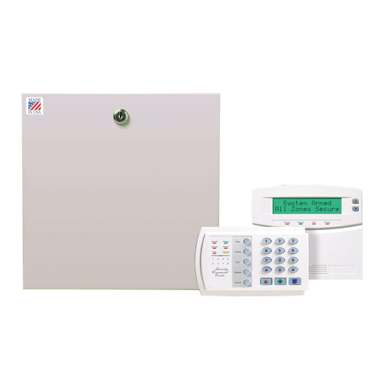
This is the GE NX-6V2-Control Panel Installation Instructions.
Installations should only be done by trained professionals.
Use this document to install the system with default settings
that comply with UL requirements.
To install the keypad, other peripherals, and sensors, refer to
the documentation for those devices.
Installation
There are four slots for board insertions inside the metal
enclosure, two on the top and two on the bottom. These allow
the PC board to be positioned vertically (Figure 1). When you
slide the board between the grooves of the slots, make sure
the terminal strip is toward the front opening (toward you) to
allow for the wire connections.
Note: Install the metal enclosure with the door opening from the top
to bottom.
Figure 1. Board installation
NetworX keypad maximum wire run
Table 1 lists wire lengths for one keypad at the end of the
wire. When connecting more than one keypad to the end of
the wire, a higher gauge wire is required.
Table 1.
Maximum keypad wire run
Length in feet
Wire gauge for NX-6V2
250
24
500
20
1000
18
1500
16
2500
14
Installation Instructions
Terminal descriptions
Table 2 describes the panel terminals.
Table 2.
Terminal
R1
R
T
T1
EARTH
AC
Bell + and
Bell -
KP DATA
KP COM
KP POS
COM
AUX PWR +
ZONE 6
COM
ZONE 5
ZONES 1 to
4
AUXOUT 4
(SMOKE +)
Wire gauge for NX320-E
22
18
16
AUXOUT 1
to 3
14
12
NX-6V2-Control Panel
466-2338A • October 2009
NX-6V2 terminals
Description
House telephone ring (grey).
Telephone ring (red).
Telephone tip (green).
House telephone tip (brown).
Earth ground. Connect to a cold water pipe or a 6 to 10 ft.
driven rod.
AC input. Connect to a 16.5 V, 40 or 50 VA Class II UL
approved transformer.
If used as a siren output (default), the speaker rating should
be 15 watt at 8 or 16 ohm, or 30/40 watt at 4, 8, or 16 ohms. If
voltage ouput is selected in location 37, this output becomes
voltage output, 12 VDC, 1 Amp maximum load. Note: A 3.3
kohm resistor may be required across the bell terminals
when a 12 VDC siren is used. If no resistor is used, you may
experience voltage leakage into the siren, which will cause
these devices to output a small signal.
Connect to the data terminal on the keypads and the
expanders. Maximum number of devices is 16 keypads plus 3
other de vices. See Maximum Wire Run table.
Connect to the common terminal on the keypads and the
expanders.
Connect to the POS terminal on the keypads and the
expanders. Individually, this terminal is limited to 1 amp.
Combined, this terminal and AUX PWR+ are limited to 2 amps
total current.
Common negative wire of powered devices such as motion
detectors and smoke detectors.
Connect positive wire of all powered devices except smoke
detectors and keypads. Individually, this terminal is limited to
1 amp. Combined, this terminal and KP POS are limited to 2
amps total current.
Connect to one side of zone 6 loop. Connect the other side to
com terminal. Open or short causes alarm. Only zone 6 can
be used for a two-wire smoke detector, connected with a 680
ohm EOL resistor. Refer to the wiring diagram. Program loca-
tion 37, segment 6, option 1. Only zone 6 can be a two-wire
zone.
Common (-) terminal for zones 5 and 6.
Connect to one side of zone 5 loop. Connect the other side to
COM terminal. Open or short causes alarm.
Connect as described for zones 5 and 6.
Smoke detector power 12 VDC (for those jurisdictions which
allow the Priority zone to be used with smoke detectors).
Current limited to 250 mA when output is positive and 250 uA
when output is negative. This output defaults to Smoke
Power, but can be reconfigured. Zone 7 may be used for a 2-
wire smoke detector using a 680 ohm EOL resistor.
Connect negative lead of low current device [relay, LED
(install 1kohm resistor in series with LED), etc.] Connect posi-
tive lead of device to COM. Current is limited to 50 mA when
output is negative, and 250 uA when output is positive.
© 2009 GE Security, Inc.
Advertisement
Table of Contents

Related Manuals for GE NX-6V2


Summary of Contents for GE NX-6V2
-
Page 1: Installation Instructions
© 2009 GE Security, Inc. Introduction Terminal descriptions Table 2 describes the panel terminals. This is the GE NX-6V2-Control Panel Installation Instructions. Table 2. NX-6V2 terminals Installations should only be done by trained professionals. Use this document to install the system with default settings... -
Page 2: Control Panel Programming
To exit before the last segment, press # (Armed LED illu- minates). Note: The NX-6V2 control panel sends a trouble condition once each You are now ready to enter another programming location. If hour if it senses that no devices have been enrolled. This report you attempt to program an invalid entry for a particular shows expander trouble--device zero (0). - Page 3 If a speaker is attached to the NX-6V2, it clicks at this Universal 4+2 Two-digit event code 1800 Hz transmit time. If a siren or bell is attached to the NX-6V2, it sounds 2300 Hz handshake double round parity for about one second. If the module is not detected, the 40 pps Service LED illuminates.
- Page 4 Program the backup control for phone 1. The default is 0. 2. On for 2300 Hz handshake; off for 1400 Hz. • Program a 0 in segment 2 to cause the NX-6V2 to make 3. On for cksum parity; off for double round parity.
-
Page 5: Underwriters Laboratories Information
Underwriters laboratories information zone bypasses when the group bypass command is entered at the keypad. The NetworX NX-6V2 holds the following listings from Under- 17. Entry/exit delay 1 with A trip starts entry delay 1. The lack of a trip... - Page 6 NX-6V2-Control Panel Installation Instructions When installing an NX-6V2 in compliance with Underwriters • Bell output (sirens): Wheelock models: NS-1215W, Laboratories, the following instructions must be observed: NS-121575W, NS4-1215W, NS4-121575W, AS- 1215W, AS-121575W • Initiating and indicating devices must be rated at 11.5 to •...
-
Page 7: Specifications
The following requirements apply to residential fire, residen- number 22-156 for UL or tial burglary, and commercial burglary installations. 22-156-CN for Canadian installations) • The NetworX NX-6V2 panel is necessary to initiate resi- Loop resistance dential and commercial installations. Standard loop 300 ohms maximum •... -
Page 8: Ansi/Sia Cp-01 Requirements
Refer to your keypad installation manual. Combined abort window time and entry delay must not exceed one minute. Technical support 888 GE Security (888.437.3287). Toll-free in the US, Puerto Rico, and Canada. 503.885.5700 outside the toll-free area or contact your local dealer. www.gesecurity.com...