Pioneer VSX-819H-K Service Manual
Audio/video multi-channel receiver
Hide thumbs
Also See for VSX-819H-K:
- Operating instructions manual (212 pages) ,
- Catalog (8 pages) ,
- Specification sheet (2 pages)
Table of Contents
Advertisement
ORDER NO.
RRV3894
VSX-819H-K
AUDIO/VIDEO MULTI-CHANNEL RECEIVER
VSX-819H-K
THIS MANUAL IS APPLICABLE TO THE FOLLOWING MODEL(S) AND TYPE(S).
Model
Type
Power Requirement
Remarks
VSX-819H-K
KUCXCN
AC 120 V
For details, refer to "Important Check Points for good servicing".
PIONEER CORPORATION
4-1, Meguro 1-chome, Meguro-ku, Tokyo 153-8654, Japan
PIONEER ELECTRONICS (USA) INC. P.O. Box 1760, Long Beach, CA 90801-1760, U.S.A.
PIONEER EUROPE NV Haven 1087, Keetberglaan 1, 9120 Melsele, Belgium
PIONEER ELECTRONICS ASIACENTRE PTE. LTD. 253 Alexandra Road, #04-01, Singapore 159936
PIONEER CORPORATION
2009
T-ZZK MAR.
2009 Printed in Japan
Advertisement
Table of Contents

Related Manuals for Pioneer VSX-819H-K


Summary of Contents for Pioneer VSX-819H-K
- Page 1 PIONEER CORPORATION 4-1, Meguro 1-chome, Meguro-ku, Tokyo 153-8654, Japan PIONEER ELECTRONICS (USA) INC. P.O. Box 1760, Long Beach, CA 90801-1760, U.S.A. PIONEER EUROPE NV Haven 1087, Keetberglaan 1, 9120 Melsele, Belgium PIONEER ELECTRONICS ASIACENTRE PTE. LTD. 253 Alexandra Road, #04-01, Singapore 159936...
-
Page 2: Safety Information
, a l way s c o n s u l t t h e c u r r e n t P I O N E E R Service Manual. A subscription to, or additional copies Also test with plug reversed of, PIONEER Ser vice Manual may be obtained at a (Using AC adapter Earth nominal charge from PIONEER. - Page 3 To protect products from damages or failures during transit, the shipping mode should be set or the shipping screws should be installed before shipment. Please be sure to follow this method especially if it is specified in this manual. VSX-819H-K...
-
Page 4: Table Of Contents
11.5 P.C.B SUB ASSY (INPUT-819)............................84 11.6 P.C.B SUB ASSY (VIDEO-819)...........................86 11.7 P.C.B SUB ASSY (SPEAKER-819) ..........................90 11.8 P.C.B SUB ASSY (DSP) and P.C.B SUB ASSY (CNT) ....................92 11.9 P.C.B SUB ASSY (HDMI-819).............................96 11.10 P.C.B SUB ASSY (USB)............................98 12. PCB PARTS LIST ................................99 VSX-819H-K... -
Page 5: Service Precautions
GYP1008 0.3 in dia. 1.2 CAUTION • Discharging For more detail, please refer to “7. DISASSEMBLY - 1. Discharging”. • Notes on Ground Points Connection For more detail, please refer to “7. DISASSEMBLY - 2. Notes on Ground Points Connection”. VSX-819H-K... -
Page 6: Specifications
IR signal ....High Active (High Level : 2.0 V) Accessories iPod cable (L308102013010-IL) Remote control (8300753100010-IL) AM loop antenna FM wire antenna AAA size IEC R03 Microphone (E601016000010-IL) (E605010070001-IL) (for Auto MCACC setup) Dry cell batteries (x2) (M040000300100-IL) VSX-819H-K... -
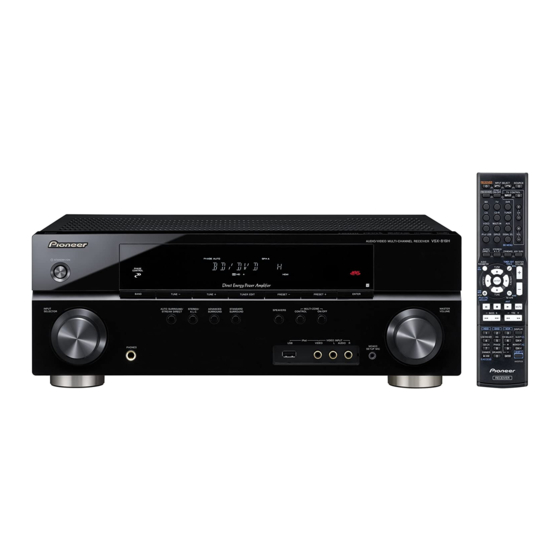
Page 7: Panel Facilities
TV/SAT SPEAKERS Class 2 Wiring COAXIAL ASSIGNABLE MONITOR OUT BD/DVD IN TV/SAT IN BD/DVD ANTENNA (CD) SURROUND CENTER FRONT OPTICAL SIRIUS (AUX) (TV/SAT) (CD-R/TAPE) (BD/DVD) LOOP BD/DVD IN ASSIGNABLE SUBWOOFER ASSIGNABLE DIGITAL AUDIO BD/DVD MULTI CH IN COMPONENT VIDEO VSX-819H-K... - Page 8 Lights when a source with DTS-EXPRESS or DTS-HD encoded audio signals is detected. Lights when a source with DTS-ES encoded audio signals is detected. 96/24 Lights when a source with DTS 96/24 encoded audio signals is detected. VSX-819H-K...
- Page 9 Displays the HOME MENU screen. RETURN Confi rm and exit the current menu screen. MENU Displays the TOOLS menu screen of Blu-ray Disc player. Press TUNER or SIRIUS fi rst to access: T.EDIT Memorizes stations for recall. When TUNER is pressed, VSX-819H-K...
- Page 10 Use to adjust the channel level. SB CH Press to select ON, AUTO, OFF the surround back channel. PHASE Press to switch on/off Phase Control. DIMMER Dims or brightens the display. The brightness can be controlled in four steps. SPEAKERS VSX-819H-K...
-
Page 11: Basic Items For Service
Item to be checked regarding video Item to be checked regarding audio Block noise Distortion Horizontal noise Noise Flicker Volume too low Disturbed image (video jumpiness) Volume too high Too dark Volume fluctuating Too bright Sound interrupted Mottled color VSX-819H-K... -
Page 12: Pcb Locations
2..P.C.B SUB ASSY (DSP) 7028067561010-IL 2..P.C.B SUB ASSY (INPUT-819) 7028067531030-IL 1..P.C.B TOTAL ASSY (HDMI-819) 7025HK0811016-IL 1..P.C.B TOTAL ASSY (SPEAKER-819) 7025HK0811033-IL 2..P.C.B SUB ASSY (HDMI-819) 7028067571010-IL 2..P.C.B SUB ASSY (SPEAKER-819) 7028067601020-IL 1..P.C.B TOTAL ASSY (USB) 7025HK0811017-IL 2..P.C.B SUB ASSY (USB) 7028067591010-IL VSX-819H-K... -
Page 13: Jigs List
8P extension jig GGD1629 Diagnosis cable Diagnosis Board to board extension jig GGD1630 cable Lubricants and Glues list Name Lubricants and Glues Remarks Silicon grease GEM1057 Refer to "9.2 EXTERIOR SECTION" Silicon adhesive GYA1011 (KE40RTV-W) Refer to "9.2 EXTERIOR SECTION" VSX-819H-K... -
Page 14: Block Diagram
4. BLOCK DIAGRAM 4.1 OVERALL CONNECTION DIAGRAM P.C.B SUB ASSY P.C.B SUB ASSY (SPEAKER-819) (7028067601020-IL) P.C.B SUB ASSY (7028067501030-IL P.C.B SUB ASSY (AMP) (7028067521010-IL) P.C.B SUB ASSY (FUNCTION) P.C.B SUB (7028067514010-IL) ASSY (HEADPHONE) (7028067512010-IL) P.C.B SUB ASSY (USB) (7028067591010-IL) VSX-819H-K... - Page 15 P.C.B SUB ASSY (INPUT-819) P.C.B SUB (7028067531030-IL) ASSY (P/T) (7028067505010-IL) SUB ASSY (MAIN) 67501030-IL) 1/2,2/2 P.C.B SUB ASSY (DSP) (7028067561010-IL) P.C.B SUB ASSY (FRONT) (7028067511010-IL) P.C.B SUB ASSY (VOLUME) (7028067513010-IL) P.C.B SUB ASSY (MIC) P.C.B SUB (7028067516010-IL) ASSY (F-VIDEO) (7028067515010-IL) VSX-819H-K...
-
Page 16: Audio Block Diagram
4.2 AUDIO BLOCK DIAGRAM P.C.B SUB ASSY P.C.B SUB ASSY (USB) (HDMI-819) P.C.B SUB ASSY (MAIN) P.C.B SUB ASSY (DSP) P.C.B SUB ASS (MIC) VSX-819H-K... - Page 17 P.C.B SUB ASSY (SPEAKER-819) P.C.B SUB ASSY (INPUT-819) P.C.B SUB ASSY P.C.B SUB ASSY P.C.B SUB ASSY (MIC) (AMP) (HEADPHONE) VSX-819H-K...
-
Page 18: Video Block Diagram
4.3 VIDEO BLOCK DIAGRAM P.C.B SUB ASSY (F-VIDEO) P.C.B SUB ASSY (VIDEO-819) VSX-819H-K... -
Page 19: U-Com Block Diagram
4.4 U-COM BLOCK DIAGRAM P.C.B SUB ASSY (FRONT) VSX-819H-K... -
Page 20: Power Supply Block Diagram
4.5 POWER SUPPLY BLOCK DIAGRAM S1(AMP B+/B-) S2(+12V,-12V) MAIN TRANS S3(DSP, HDMI) S4(DIR/CODEC, HDMI, USB) AC CORD S4(FLT) SUB TRANS VSX-819H-K... -
Page 21: Diagnosis
3.3 V Replace REG103. output? *The I/O power of DSP Assy is OK ZD200 kathode Is the Check the ZD200 2.4 VB voltage of 2.5 V and IC106. output? *The IC106 power of DSP Assy To Step 3 VSX-819H-K... - Page 22 0 V : DIR 3.3 V : HDMI Is there To Step 6 Replace IC109. a LR clock output? (0 V ⇔ 3.3 V) IC109 (Pin 14) DIR_SDTO (Data) Is there a data Replace IC109. output? (0 V ⇔ 3.3 V) VSX-819H-K...
- Page 23 (0 V ⇔ 3.3 V) Surround back L/R data IC109 (Pin 25) Is there a data input? (0 V ⇔ 3.3 V) Check the path between IC102 and data & address lines. SDRAM (IC100), FLASH ROM (IC101) To Step 7 VSX-819H-K...
- Page 24 Replace IC109. output? Is the output Replace IC109. 2.5 V fixing? LFE out IC109 (Pin 39) Is there IC109 (Pin 39) LFE out Replace IC109. a audio signal output? Is the output Replace IC109. 2.5 V fixing? VSX-819H-K...
-
Page 25: Hdmi Troubleshooting
Turn on the power of the Receiver and equipments which was connected with HDMI. Function switch (BD, TV or DVR) Switch the function that HDMI was assigned. Factory shipments setting: HDMI 1: BD/DVD HDMI 2: TV/SAT HDMI 3: DVR/VCR To Step 2 VSX-819H-K... - Page 26 Check the path between them. patterns in the path. Replace Q1204, IC1003, etc. To Step 3 Is Q1405 replace Q1405 collector voltage 0 V? (base is 3.3 V) Check the parts and patterns in the path Q1405, Q1204, etc. VSX-819H-K...
- Page 27 IC1001 (Pin 4) Is there Check the parts and patterns in a data output? the path IC1003. (0 to 3.3 V) Is there Check the path to pin4 of IC1001. a 27 MHz Replace IC1001. output? To Step 5 VSX-819H-K...
- Page 28 * When connected the equipment to IN3 (DVR/VCR) To Step 6 JACK1001 (Pin 19) HPD1 Is the Check the JACK1001 and IC1001. voltage 5 V If JACK1001 or IC1001 is failure, when selecting replace JACK1001 or IC1001. IN1? To Step 7 VSX-819H-K...
- Page 29 IC1001 or JACK1003. IN1? IC1002 (Pins 30,31,33,34,36,37,39,40) TMDS OUTPUT (0 to 5 V) Check the IC1001 or IC1002. Are there signals(approx. 0.5 If IC1001 or IC1002 is failure, Vp-p) in all replace IC1001 or IC1002. lines? VSX-819H-K...
- Page 30 I / U E R R 4 No Track i P o d No Music Track Cautuion When a track does not exist in the selected T r a c k category T R A C K [Procedure] Select another category. VSX-819H-K...
- Page 31 CN801. 5 V output? Replace REG2. The output and GND may be To STEP 2 short-circuited. Check the path between them. 5 V input REG1 (pin 3) Check the patterns in the voltage the path. 5 V ? VSX-819H-K...
- Page 32 DATA and ADDRESS lines turning the power between SDRAM (IC803), on and several seconds FLASH ROM (IC802) and IC801 later, does SDCLK change 12 MHz to 80 MHz? are may not be connected. Operation of IC801 is OK. To STEP 3 VSX-819H-K...
- Page 33 To STEP 4 Step 4 Audio Out check CN805 (pin 1) S/PDIF output Is there Check the a S/PDIF path between IC801 Replace IC801. signal (pin 105) Check the parts and pattern CN805 and IC801. Refer to the DSP Assy troubleshooting. VSX-819H-K...
-
Page 34: Detection Circuit
5.2 DETECTION CIRCUIT [1] DC Protection Circuit Diagram VSX-819H-K... - Page 35 [2] Overload Protection Circuit Diagram VSX-819H-K...
- Page 36 [3] Power DC Protection Circuit Diagram VSX-819H-K...
-
Page 37: Service Mode
5 (-> normal) *1 Number of abnormal-temperature [ENTER key] error detections Counter (Initial display) *1 “5 (-> normal)” denotes that the display will return to the normal indication when no key operation is performed for 5 seconds. *2 Variable range: 0-255 VSX-819H-K... - Page 38 1. When the procedures for Reset mode for numbers of protection detections are completed, all the counters will be reset to “000.” 2. Prohibitions: The protection detection counts cannot be cleared (reset to 000) with the MEMORY CLEAR process. They can only be cleared when the procedures of Reset mode are completed. VSX-819H-K...
- Page 39 Normal display (Normal display) [Detailed explanations] Simultaneously holding the [ADVANCD SURROUND] and [STANDBY/ON] keys on the front panel pressed for 2 seconds will cancel Key Input Inhibition mode after a DC error detection and turn the unit ON. VSX-819H-K...
-
Page 40: Disassembly
(3) Check that the voltage between the -30 V and GND terminals is less than 1 V, using a tester. *Be sure to connect the GND terminal of the tester to the chassis. *If the voltage is still 1 V or higher, repeat Step (2). 47-100 ohms (2 W or higher) P.C.B SUB Assy (FRONT) VSX-819H-K... - Page 41 Without grounding connection, the protection circuit will be activated. After repairing, be sure to remove the ground wire before reassembling. REAR CHASSIS TUNER PACK CHASSIS GND WIRE (Be sure to disconnect the GND wire before reassembly.) MAIN CAPAITOR GND P.C.B SUB Assy (MAIN) VSX-819H-K...
- Page 42 2. Remove the two screws. (BBZ30P080FTC) P.C.B SUB Assy P.C.B SUB Assy (GUIDE PCB L) (GUIDE PCB R) 3. Remove the two screws. 4. Unhook the two hooks. 5. Arrange the front panel section as shown in the photo below. Front panel section VSX-819H-K...
- Page 43 • Bottom view 2. Remove the four screws. (BBZ30P080FTC) P.C.B SUB Assy P.C.B SUB Assy (GUIDE PCB L) (GUIDE PCB R) 3. Disconnect the two connectors. P.C.B SUB Assy (INPUT-819) P.C.B SUB Assy (AMP) CP801 P.C.B SUB Assy (MAIN) CP107 VSX-819H-K...
- Page 44 Note: P.C.B SUB Assy (AMP) The Power transistor and heat sink on the P.C.B SUB Assy (MAIN) come closer. Make sure that they will not come into contact. Power transistor P.C.B SUB Assy (MAIN) Heat sink Heat sink section VSX-819H-K...
- Page 45 P.C.B SUB Assy (MAIN) 2. Remove the three screws. (BBZ30P080FTC) 3. Remove the six screws. (BBZ30P180FTC) 4. Arrange the unit as shown in the photo below. 5. Connect the chassis ground. See “2. Notes on Ground Points Connection”. P.C.B SUB Assy (MAIN) VSX-819H-K...
- Page 46 • Rear view 2. Remove the one screw. (BMZ30P100FTB) ×22 3. Remove the 22 screws. (BBT30P100FTB) ×4 4. Remove the five screws. (BBT30P100FTB) P.C.B SUB Assy (DSP) 5. Remove the rear chassis. 6. Remove the P.C.B SUB Assy (DSP). Rear chassis VSX-819H-K...
- Page 47 See “2. Notes on Ground Points Connection”. CP200 CN206 8. Reassembling the rear chassis. 9. Connect the board to board extension jig cable. Connect an alligator clip to the chassis. Rear chassis Board to board extension jig cable (GGD1630) P.C.B SUB Assy (DSP) VSX-819H-K...
-
Page 48: Each Setting And Adjustment
Idle current Idle current VR: VR201FR VR: VR201SR VR: VR201C VR: VR201SL VR: VR201FL TP201FR 3PIN TP201SR 3PIN TP201C 3PIN TP201SL 3PIN TP201FL 3PIN TEST POINT(+) TEST POINT(+) TEST POINT(+) TEST POINT(+) TEST POINT(+) TP201FR 1PIN TEST POINT(-) [fig 1.] VSX-819H-K... - Page 49 VSX-819H-K...
-
Page 50: Exploded Views And Parts List
For the applying amount of lubricants or glue, follow the instructions in this manual. (In the case of no amount instructions, apply as you think it appropriate.) 9.1 PACKING SECTION POLY BAG PACKING STYLE TAPE(CLEAR) S E T CORD AC VSX-819H-K... - Page 51 • • • • • 20 Microphone M040000300100-IL (for Auto MCACC setup) 21 • • • • • 22 • • • • • 23 • • • • • 24 • • • • • 25 iPod Cable L308102013010-IL VSX-819H-K...
-
Page 52: Exterior Section
9.2 EXTERIOR SECTION NON-CONTACT SIDE CONTACT SIDE VSX-819H-K... - Page 53 S5 *4 S4 *4 S1 *4 Silicon adhesive GYA1011 S2 *32 Silicon grease GEM1057 VSX-819H-K...
- Page 54 Description Part No. Mark No. Description Part No. 50 Cabinet 3007211276010-IL 1 Window 5077212673000-IL 2 Pioneer Badge B XAM3006 51 Cushion 4050211205000-IL 3 Knob 5080211931100-IL 52 P.C.B SUB ASSY (H/P GUIDE) 7028067506010-IL 4 Cushion 4050211745000-IL 53 P.C.B SUB ASSY (P/T)
- Page 55 VSX-819H-K...
-
Page 56: Schematic Diagram
10.1 P.C.B SUB ASSY (MAIN) and P.C.B SUB ASSY (P/T) CP403 CN803 CP402 CP405 CN202 CN202 CN201 P.C.B SUB ASSY (P/T) (7028067505010-IL) • NOTE FOR FUSE REPLACEMENT CAUTION - FOR CONTINUED PROTECTION AGAINST RISK OF FIRE. REPLACE WITH SAME TYPE AND RATINGS OF FUSE. VSX-819H-K... - Page 57 The > mark found on some component parts indicates the importance of the safety factor of the part. Therefore, when replacing, be sure to use parts of identical designation. : The power supply is shown with the marked box. CN201 CN803 CN203 CN804 CN204 CP704 CN807 P.C.B SUB ASSY (MAIN) (7028067501030-IL) VSX-819H-K...
-
Page 58: Sub Assys (Front), (Volume), (Function), (Headphone), (F-Video) And (Mic)
10.2 P.C.B SUB ASSYS (FRONT), (VOLUME), (FUNCTION), (HEADPHONE), (F-VIDEO) and (MIC) P.C.B SUB ASSY (FRONT) (7028067511010-IL) P.C.B SUB ASSY (VOLUME) (7028067513010-IL) P.C.B SUB ASSY (FUNCTION) (7028067514010-IL) FPC101 C A D E VSX-819H-K... - Page 59 P.C.B SUB ASSY (F-VIDEO) (7028067515010-IL) P.C.B SUB ASSY (HEADPHONE) (7028067512010-IL) P.C.B SUB ASSY (MIC) (7028067516010-IL) : Video Signal Route : Audio Signal Route (L ch) C A F G H VSX-819H-K...
-
Page 60: Sub Assy (Amp)
10.3 P.C.B SUB ASSY (AMP) P.C.B SUB ASSY (AMP) (7028067521010-IL) (FL) (FL) (SL) (SL) (SL) (FL) : Audio Signal Route (Front L ch) (SL) : Audio Signal Route (Surround L ch) : Audio Signal Route (Center ch) VSX-819H-K... - Page 61 (FL) (FL) (SL) (SL) (SL) VSX-819H-K...
-
Page 62: Sub Assy (Input-819)
10.4 P.C.B SUB ASSY (INPUT-819) P.C.B SUB ASSY (INPUT-819) (7028067531030-IL) CN206 CP117 CP118 CP119 VSX-819H-K... - Page 63 CP802 20010WA-06A MCACC J802 & F.AUX J801 R892,R900 470 Q812,Q814 KTC2875B R901 R894 R895 470K C896 10N-K R902 Q813 KRA102S D811,D812 R863 WOOFER R869 Q810,Q811 R950,R951 470K SIRIUS JK802,3,4 JACK RCA-610D-00-02 R972,R973 SB CH C935,C936 2N2-K CP119 CN702 CP120 VSX-819H-K...
-
Page 64: Sub Assy (Video-819)
: Video Signal Route L L H H L H : Video Signal Route (Component Y ch) L H H CP122 CP123 (Cb) : Video Signal Route (Component Cb ch) H H H (Cr) : Video Signal Route (Component Cr ch) VSX-819H-K... - Page 65 * AREA OPTION /KUCXCN (NTSC) XTAL1001 14M318(18P) J1005 JUMPER XTAL1002 J1004 Q1015 Q1016 Q1017 * AREA OPTION (SW) (SBL) (SBL) : Audio Signal Route (Surround Back L ch) (SW) : Audio Signal Route (SubWoofer ch) CP123 CP124 VSX-819H-K...
-
Page 66: Sub Assy (Speaker-819) And P.c.b Sub Assy (Cnt)
10.6 P.C.B SUB ASSY (SPEAKER-819) and P.C.B SUB ASSY (CNT) P.C.B SUB ASSY (SPEAKER-819) (7028067601020-IL) (FL) (FL) (FL) (FL) (SL) (SL) (FL) : Audio Signal Route (Front L ch) (SL) : Audio Signal Route (Surround L ch) : Audio Signal Route (Center ch) VSX-819H-K... - Page 67 P.C.B SUB ASSY (CNT) (7028067504010-IL) VSX-819H-K...
-
Page 68: Sub Assy (Dsp) (1/2)
10.7 P.C.B SUB ASSY (DSP) (1/2) P.C.B SUB ASSY (DSP) (7028067561010-IL) CP803 Ref. NO. VSX-819 REMARK IC102 TMS320DA788 CN202 TUC-P15X-B1 CP105 5268-03A R136 BD121T CP113 CP114 VSX-819H-K... - Page 69 : Audio Signal Route (Front L ch) (SL) : Audio Signal Route (Surround L ch) : Audio Signal Route (Center ch) (SW) : Audio Signal Route (SubWoofer ch) (SBL) : Audio Signal Route (Surround Back L ch) CP114 CP115 VSX-819H-K...
- Page 70 10.8 P.C.B SUB ASSY (DSP) (2/2) P.C.B SUB ASSY (DSP) (7028067561010-IL) CP116 VSX-819H-K...
- Page 71 VSX-819H-K...
-
Page 72: Sub Assy (Usb)
10.9 P.C.B SUB ASSY (USB) P.C.B SUB ASSY (USB) CP105 (7028067591010-IL) VSX-819H-K... - Page 73 CP705 CP105 VSX-819H-K...
-
Page 74: Pcb Connection Diagram
P.C.B SUB ASSY (MAIN) CP403 CP405 CP403 CN103 CN106 CN104 Q125 Q122 Q121 Q123 Q124 IC104 IC111 IC112 Q106 Q107 IC103 IC115 Q108 CP12 Q129 Q132 Q135 Q128 Q131 Q134 Q130 Q136 Q133 P.C.B SUB ASSY (P/T) Q126 Q127 VSX-819H-K... - Page 75 SIDE A For further information for respective destinations, be sure to check with the schematic diagram. SIDE B CP122 CP123 P.C.Board Chip Part CP129 CP121 CP110 CP105 CP126 CP125 CN701 CN807 CP804 CN701 CP200 CP117-120 CP113-116 CN803,804,806,807 CN201-204 P/T) VSX-819H-K...
- Page 76 SIDE B P.C.B SUB ASSY (MAIN) IC108 IC110 IC109 Q138 IC120 Q300 Q101 Q111 Q109 Q302 IC301 IC302 Q110 Q301 IC106 IC101 Q103 Q202 Q102 Q201 IC113 VSX-819H-K...
- Page 77 SIDE B P.C.B SUB ASSY (P/T) VSX-819H-K...
-
Page 78: Sub Assys (Front)
11.2 P.C.B SUB ASSYS (FRONT) SIDE A P.C.B SUB ASSY (FRONT) Q702 CP705 CN802 SIDE B P.C.B SUB ASSY (FRONT) Q701 Q703 IC701 VSX-819H-K... - Page 79 SIDE A CN704 CP701 SIDE B VSX-819H-K...
-
Page 80: Sub Assys (Volume), (Function), (Headphone), (F-Video) And (Mic)
11.3 P.C.B SUB ASSYS (VOLUME), (FUNCTION), (HEADPHONE), (F-VIDEO) and (MIC) SIDE A SIDE A P.C.B SUB ASSY(VOLUME) P.C.B SUB ASSY (MIC) P.C.B SUB ASSY (HEADPHONE) P.C.B SUB ASSY (F-VIDEO) P.C.B SUB ASSY (FUNCTION) CN706 CP703 D E F G H VSX-819H-K... - Page 81 SIDE B SIDE B P.C.B SUB ASSY(VOLUME) P.C.B SUB ASSY (MIC) P.C.B SUB ASSY (HEADPHONE) P.C.B SUB ASSY (F-VIDEO) P.C.B SUB ASSY (FUNCTION) D E F G H VSX-819H-K...
-
Page 82: Sub Assy (Amp)
Q203SL Q204SL Q204FL Q206SR Q203FL Q203SR Q202SL Q202SR Q206FR Q206SL Q202FL Q206FL Q202FR VR201FL VR201FR VR201SR VR201SL VR201C Q205FR Q205SR Q205C Q201SL Q201SR Q201FL Q201C Q201FR Q207FR Q207FL Q207SL Q207FL Q207SL Q205SL Q205FL SIDE B P.C.B SUB ASSY (AMP) VSX-819H-K... - Page 83 SIDE A SIDE B VSX-819H-K...
-
Page 84: Sub Assy (Input-819)
11.5 P.C.B SUB ASSY (INPUT-819) SIDE A SIDE A P.C.B SUB ASSY (INPUT-819) IC803 IC804 IC801 Q816 Q815 Q817 IC802 Q818 CP805 CP804 CP801 CP802 CN803,804, 806,807 CN702 CP110 CN201 CN703 CN701 CN705 CP117-120 VSX-819H-K... - Page 85 SIDE B SIDE B P.C.B SUB ASSY (INPUT-819) IC801 Q812 Q813 Q814 Q801 Q802 Q803 Q805 Q804 IC802 Q807 Q806 Q808 Q809 Q810 Q811 VSX-819H-K...
-
Page 86: Sub Assy (Video-819)
11.6 P.C.B SUB ASSY (VIDEO-819) SIDE A P.C.B SUB ASSY (VIDEO-819) IC1003 IC1005 Q1006 VSX-819H-K... - Page 87 SIDE A VSX-819H-K...
- Page 88 SIDE B P.C.B SUB ASSY (VIDEO-819) Q1012 Q1008 Q1011 Q1010 IC1004 Q1007 IC1008 Q1009 Q1017 IC1001 Q1016 Q1015 IC1002 Q1014 Q1002 Q1003 IC1007 Q1004 Q1005 Q1013 VSX-819H-K...
- Page 89 SIDE B VSX-819H-K...
-
Page 90: Sub Assy (Speaker-819)
11.7 P.C.B SUB ASSY (SPEAKER-819) SIDE A SIDE A P.C.B SUB ASSY (SPEAKER-819) CP403 CN104 CP402 CN103 VSX-819H-K... - Page 91 SIDE B SIDE B P.C.B SUB ASSY (SPEAKER-819) Q404 Q402 Q403 Q401 VSX-819H-K...
-
Page 92: Sub Assy (Dsp) And P.c.b Sub Assy (Cnt)
11.8 P.C.B SUB ASSY (DSP) and P.C.B SUB ASSY (CNT) SIDE A P.C.B SUB ASSY (DSP) CN805 CP105 IC101 IC109 IC110 IC106 IC100 CN206 CN201 CN202 CP803 CP113 CP114 VSX-819H-K... - Page 93 SIDE A UPGRADE CN205 P.C.B SUB ASSY (CNT) CN203 CP115 VSX-819H-K...
- Page 94 SIDE B P.C.B SUB ASSY (DSP) Q802 IC806 P.C.B SUB ASSY (CNT) VSX-819H-K...
- Page 95 SIDE B VSX-819H-K...
-
Page 96: Sub Assy (Hdmi-819)
11.9 P.C.B SUB ASSY (HDMI-819) SIDE A SIDE A P.C.B SUB ASSY (HDMI-819) IC1002 IC1001 IC1003 VSX-819H-K... - Page 97 SIDE B SIDE B P.C.B SUB ASSY (HDMI-819) Q1002 Q1004 Q1006 Q1001 Q1003 Q1005 Q1201 Q1405 IC1005 Q1402 Q1403 IC1004 Q1401 Q1204 VSX-819H-K...
-
Page 98: Sub Assy (Usb)
11.10 P.C.B SUB ASSY (USB) SIDE A SIDE A P.C.B SUB ASSY (USB) IC803 IC801 CN802 CP705 SIDE B SIDE B P.C.B SUB ASSY (USB) IC802 IC804 VSX-819H-K... -
Page 99: Pcb Parts List
2..P.C.B SUB ASSY (INPUT-819) 7028067531030-IL JA 101 TUNER E903004100020-IL JA 102 TER,BOARD PUSH 2P G592212A0300Y-IL 1..P.C.B TOTAL ASSY (SPEAKER-819) 7025HK0811033-IL JA 1011 JACK,DIN G403515397000-IL 2..P.C.B SUB ASSY (SPEAKER-819) 7028067601020-IL RY 101 RELAY G680120502050-IL RY 302 RELAY G680060502010-IL T 301 POWER TRANS 8200280150620-IL VSX-819H-K... - Page 100 S 701-714 SWITCH G180040500010-IL R 2021-2025,2071-2075 C060056265050-IL 0000 HOLDER 432004078301A-IL R 2031-2035 C00002226P520-IL R 2041-2045 C00004746P520-IL RESISTORS R 779,780 C0602R2063050-IL R 2051-2055,2231-2235 C0604R7063050-IL R 2061-2065 C00001036P520-IL CAPACITORS R 2081-2085 C00005626P520-IL C 718,719 D02047306C060-IL R 2091-2095,2101-2105 N113136647820-IL R 2111-2115 C00002216P520-IL VSX-819H-K...
- Page 101 Q 1001-1006 J522390400010-IL MISCELLANEOUS Q 1201 J522104S00210-IL L 1001 COIL,FILTER-INDUCTOR D330330700520-IL Q 1204 J500124200010-IL JA 1001 TER,RCA G608610D0210Y-IL Q 1401 J5232114K0010-IL JA 1002 TER,RCA G608610D0209Y-IL Q 1402,1403 J522038750210-IL JA 1003 TER,RCA 9PIN G607902AD016Y-IL X 1001 CRYSTAL E80014R318080-IL Q 1405 J522010200210-IL VSX-819H-K...
- Page 102 341S2164 IC 805 J046205100010-IL J522010200210-IL J520103S00210-IL D 3,4 K005041480030-IL MISCELLANEOUS JA 801 CN,PLUG CONTACT G480040400020-IL CRYSTAL E80012R000010-IL P.C.B SUB ASSY (GUIDE-L) MISCELLANEOUS JHMX9800(ON)HAITI) 4330000120000-IL P.C.B SUB ASSY (GUIDE-R) MISCELLANEOUS JHMX9800(ON)HAITI) 4330000120000-IL P.C.B SUB ASSY (H/P GUIDE) MISCELLANEOUS BRACKET 4010210196000-IL VSX-819H-K...