Table of Contents
Advertisement
Advertisement
Table of Contents

Related Manuals for Toro TimeCutter HD MyRide 48in


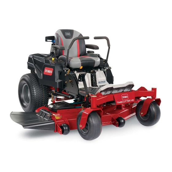
Summary of Contents for Toro TimeCutter HD MyRide 48in
- Page 1 Form No. 3415-511 Rev A TimeCutter ® HD MyRide 48in, 54in, and 60in Riding Mower Model No. 75211—Serial No. 400000000 and Up Model No. 75212—Serial No. 400000000 and Up Model No. 75213—Serial No. 400000000 and Up *3415-511* A Register at www.Toro.com. Original Instructions (EN)
-
Page 2: Figure
Whenever you need service, genuine Toro parts, or mower model. additional information, contact an Authorized Service Important: Dealer or Toro Customer Service and have the model If you are using a machine with a Toro and serial numbers of your product ready. Figure 1... - Page 3 Using the Smart Speed Control System............24 Model No. Stopping the Machine ........24 Using the Side Discharge ......... 25 Serial No. Adjusting the Height of Cut ....... 26 Adjusting the Anti-Scalp Rollers......27 Using Attachments and Accessories....27 This manual identifies potential hazards and has Operating Tips ..........
-
Page 4: Safety
Safety This machine has been designed in accordance with ANSI B71.1-2012. General Safety This product is capable of amputating hands and feet and of throwing objects. Always follow all safety instructions to avoid serious personal injury. Using this product for purposes other than its intended use could prove dangerous to you and bystanders. -
Page 5: Slope Indicator
Slope Indicator G011841 g011841 Figure 4 This page may be copied for personal use. 1. The maximum slope you can safely operate the machine on is 15 degrees. Use the slope chart to determine the degree of slope of hills before operating. Do not operate this machine on a slope greater than 15 degrees. Fold along the appropriate line to match the recommended slope. -
Page 6: Safety And Instructional Decals
Safety and Instructional Decals Safety decals and instructions are easily visible to the operator and are located near any area of potential danger. Replace any decal that is damaged or missing. decaloemmarkt Manufacturer's Mark 1. Indicates the blade is identified as a part from the original machine manufacturer. - Page 7 decal130-0765 decal131-1097 130-0765 131-1097 1. Read the Operator's 3. Remove the key from 1. Oil drain Manual. the ignition and read the Operator's Manual before performing maintenance. 2. Height-of-cut selection decal132-0872 132-0872 1. Thrown object 3. Severing hazard of hand hazard—keep bystanders or foot—keep away from away from the machine.
- Page 8 decal132-0869 132-0869 1. Warning—read the Operator's Manual. 5. Ramp hazard—When loading onto a trailer, do not use split ramps. Only use a full-width ramp wide enough for the machine. Ramp angle with the ground should be less than 15 degrees. Back up the ramp and drive forward off the ramp. 2.
- Page 9 decal133-9263 133-9263 1. Fast 4. PTO disengage 2. Slow 5. PTO engage 3. Choke decal136-4243 136-4243 1. Fast 4. Reverse 2. Slow 5. Parking brake disengaged 3. Neutral 6. Parking brake engaged decal136-4245 136-4245 3. Fast 1. Slow 2. Transport decal136-4244 136-4244 1.
- Page 10 decal136-5596 136-5596 1. Check the tire pressure 4. Check the tire pressure every 25 operating hours. every 25 operating hours. 2. Engine oil 5. Read the Operator's Manual before performing maintenance. 3. Check the tire pressure every 25 operating hours. decal136-9186 136-9186 1.
-
Page 11: Product Overview
Controls Product Overview Become familiar with all controls in Figure 6 Figure 7 before you start the engine and operate the machine. g188738 Figure 6 1. Hour meter 4. Ignition switch 2. Throttle control 5. PTO switch 3. Choke control 6. -
Page 12: Choke Control
Authorized Service Dealer or Distributor or go to To disengage the parking brake, pull the lever out of www.Toro.com for a list of all approved attachments the detent slot and toward you, then push it down. and accessories. -
Page 13: Before Operation
Operation containers on the ground, away from your vehicle before filling. • Remove the equipment from the truck or trailer Note: Determine the left and right sides of the and refuel it while it is on the ground. If this is not machine from the normal operating position. -
Page 14: Using Stabilizer/Conditioner
Using Stabilizer/Conditioner Use a fuel stabilizer/conditioner in the machine to provide the following benefits: • Keeps fuel fresh during storage of 90 days or less (drain the fuel tank when storing the machine for more than 90 days) • Cleans the engine while it runs •... -
Page 15: Think Safety First
Think Safety First CAUTION This machine produces sound levels in Please read all safety instructions and symbols in the excess of 85 dBA at the operator’s ear and safety section. Knowing this information could help can cause hearing loss through extended you or bystanders avoid injury. -
Page 16: Positioning The Seat
Testing the Safety-Interlock Positioning the Seat System The seat moves forward and backward. Position the seat where you have the best control of the machine Service Interval: Before each use or daily and are most comfortable. Test the safety-interlock system before you use the To adjust, move the lever sideways to unlock the seat machine each time. -
Page 17: Adjusting The Myride™ Suspension System
Adjusting the MyRide™ Adjust the rear-shock assemblies (Figure 13). Suspension System The MyRide™ suspension system adjusts to provide a smooth and comfortable ride. Adjusting the rear 2-shock assemblies is the easiest and quickest adjustment for changing the suspension system. Position the suspension system where you are most comfortable. -
Page 18: Adjusting The Motion-Control Levers
Adjusting the During Operation Motion-Control Levers During Operation Safety Adjusting the Height General Safety You can adjust the motion-control levers higher or • The owner/operator can prevent and is responsible lower for maximum comfort (Figure 14). for accidents that may cause personal injury or property damage. - Page 19 • Do not change the governor speed or overspeed the engine. • Use accessories and attachments approved by Toro only. Slope Safety • Establish your own procedures and rules for operating on slopes. These procedures must include surveying the site to determine which slopes are safe for machine operation.
-
Page 20: Operating The Parking Brake
Operating the Parking Operating the Mower Brake Blade-Control Switch (PTO) Always engage the parking brake when you stop the The blade-control switch (PTO) starts and stops the machine or leave it unattended. mower blades and any powered attachments. Engaging the Parking Brake Engaging the Blade-Control Switch (PTO) WARNING... -
Page 21: Operating The Throttle
Operating the Throttle Operating the Ignition Switch You can move the throttle control between the F and S positions (Figure 20). 1. Turn the ignition key to the S position TART Always use the F position when turning on the (Figure 22). -
Page 22: Starting And Shutting Off The Engine
Starting and Shutting Off Using the Motion-Control the Engine Levers Starting the Engine Note: A warm or hot engine may not require choking. Important: Do not engage the starter for more than 5 seconds at a time. Engaging the starter motor for more than 5 seconds can damage the starter motor. -
Page 23: Driving The Machine
Driving the Machine Driving Forward Note: The engine stops when you move the The drive wheels turn independently, powered by traction-control with the parking brake engaged. hydraulic motors on each axle. You can turn 1 side in reverse while you turn the other forward, causing To stop, pull the motion-control levers to the N EUTRAL the machine to spin rather than turn. -
Page 24: System
Driving Backward 3. Adjust the lever to the desired position. 1. Move the levers to the center, unlocked position. The following are only recommendations for use. Adjustments vary by grass type, moisture content, 2. To go backward, slowly pull the motion-control and the height of the grass. -
Page 25: Using The Side Discharge
Using the Side Discharge CAUTION Children or bystanders may be injured if they The mower has a hinged grass deflector that move or attempt to operate the machine while disperses clippings to the side and down toward the it is unattended. turf. -
Page 26: Adjusting The Height Of Cut
Adjusting the Height of Cut 3. Select a hole in the height-of-cut system corresponding to the desired height of cut and The machine is equipped with a foot pedal deck-lift insert the pin (Figure 29). system. You can use the foot pedal to lift the deck 4. -
Page 27: Adjusting The Anti-Scalp Rollers
Adjusting the Anti-Scalp Using Attachments and Accessories Rollers Use only Toro approved attachments and accessories. Whenever you change the height-of-cut, it is recommended to adjust the height of the anti-scalp If you attach a bucket to the engine guard, use a nylon rollers. -
Page 28: Operating Tips
It is best to cut only about a third of the grass blade. genuine Toro replacement blade. Cutting more than that is not recommended unless grass is sparse, or it is late fall when grass grows more slowly. -
Page 29: After Operation
Pushing the Machine by After Operation Hand After Operation Safety Important: Always push the machine by hand. Do not tow the machine, because damage may occur. General Safety This machine has an electric-brake mechanism, and to push the machine, the ignition key must be in the •... -
Page 30: Transporting The Machine
Operating the Machine Loading the Machine Move the bypass levers rearward through the keyhole Use extreme caution when loading or unloading and down to lock them in place as shown in Figure machines onto a trailer or a truck. Use a full-width ramp that is wider than the machine for this procedure. - Page 31 g027996 g027996 Figure 34 1. Full-width ramp in stowed 4. Ramp is at least 4 times position as long as the height of the trailer or truck bed to the ground 2. Side view of full-width 5. H=height of the trailer or ramp in loading position truck bed to the ground 3.
-
Page 32: Maintenance
Maintenance Note: Determine the left and right sides of the machine from the normal operating position. Recommended Maintenance Schedule(s) Maintenance Service Maintenance Procedure Interval • Change the engine oil. After the first 5 hours • Check the safety-interlock system. • Check the air cleaner for dirty, loose, or damaged parts. •... -
Page 33: Pre-Maintenance Procedures
Check their proper operation regularly. • To ensure optimum performance and continued safety certification of the machine, use only genuine Toro replacement parts and accessories. Replacement parts and accessories made by... -
Page 34: Engine Maintenance
Engine Maintenance WARNING Contact with hot surfaces may cause personal injury. Keep your hands, feet, face, clothing, and other body parts away the muffler and other hot surfaces. g027800 g027800 Engine Safety Shut off the engine before checking the oil or adding oil to the crankcase. -
Page 35: Servicing The Engine Oil
Servicing the Paper Element Important: If you overfill or underfill the engine crankcase with oil and run the engine, you may Service Interval: Every 100 hours/Yearly (whichever damage the engine. comes first)—Service the air-cleaner 1. Park the machine on a level surface, disengage paper element (more often in dusty, the blade-control switch, shut off the engine, dirty conditions). - Page 36 Changing the Engine Oil and Oil Filter Service Interval: After the first 5 hours/After the first month (whichever comes first)—Change the engine oil. Every 100 hours/Yearly (whichever comes first)—Change the engine oil (more often in dusty, dirty conditions). g027799 Every 100 hours/Yearly (whichever comes g027799 first)—Change the oil filter (more often in dusty, dirty conditions).
-
Page 37: Servicing The Spark Plug
5. Change the engine-oil filter (Figure 40). Note: Ensure that the oil-filter gasket touches the engine and then turn the filter an extra 3/4 turn. g193530 Figure 41 Servicing the Spark Plug Service Interval: Every 100 hours/Yearly (whichever comes first)—Check the spark plug(s). -
Page 38: Cleaning The Cooling System
Installing the Spark Plug Tighten the spark plug(s) to 25 to 30 N∙m (18.5 to 22.1 ft-lb). g027478 g027478 Figure 42 Note: Due to the deep recess around the spark plug, blowing out the cavity with compressed air is the most effective method for cleaning. The 25-30 N-m spark plug is most accessible when the blower 18.5-22.1 ft-lb... -
Page 39: Fuel System Maintenance
Fuel System Maintenance DANGER In certain conditions, fuel is extremely g027939 flammable and highly explosive. A fire or g027939 explosion from fuel can burn you, others, and can damage property. • Perform any fuel-related maintenance when the engine is cold. Do this outdoors in an open area. -
Page 40: Electrical System Maintenance
Electrical System Maintenance Electrical System Safety • Disconnect the battery before repairing the machine. Disconnect the negative terminal first and the positive last. Connect the positive terminal first and the negative last. • Charge the battery in an open, well-ventilated area, away from sparks and flames. -
Page 41: Installing The Battery
g000538 Figure 48 1. Positive (+) battery post 3. Red (+) charger lead 2. Negative (–) battery post 4. Black (–) charger lead g188903 Figure 47 Installing the Battery 1. Battery 5. Positive (+) battery post 1. Position the battery in the tray (Figure 47). -
Page 42: Servicing The Fuses
Servicing the Fuses Drive System Maintenance The electrical system is protected by fuses. It requires no maintenance; however, if a fuse blows, check the component/circuit for a malfunction or short. Checking the Tire Pressure Fuse type: • Main—F1 (15 A, blade-type) Service Interval: Every 25 hours—Check tire pressure. -
Page 43: Mower Maintenance
Mower Maintenance Servicing the Cutting Blades To ensure a superior quality of cut, keep the blades sharp. For convenient sharpening and replacement, keep extra blades on hand. g006530 Figure 52 1. Cutting edge 3. Wear/slot forming Blade Safety 2. Curved area 4. - Page 44 If a bent blade is replaced with a new blade, and the dimension obtained continues to exceed 3 mm (1/8 inch), the blade spindle could be bent. Contact an Authorized Toro Dealer for service. B. If the variance is within constraints, move to the next blade. G014974 g014974 6.
-
Page 45: Removing The Blades
(Figure 58). best performance and continued safety conformance of the machine, use genuine Toro replacement blades. Replacement blades made by other manufacturers may result in non-conformance with safety standards. 1. Hold the blade end using a rag or thickly padded glove. -
Page 46: Leveling The Mower Deck
Leveling the Mower Deck Checking the Front-to-Rear Blade Slope Ensure that the mower deck is level any time you install the mower deck or when you see an uneven Check the front-to-rear blade level any time you install cut on your lawn. the mower. -
Page 47: Removing The Mower Deck
Leveling the Mower Deck 1. Set the anti-scalp rollers to the top holes or remove them completely for this procedure; refer Adjusting the Anti-Scalp Rollers (page 27). 2. Set the height-of-cut lever to the 76 mm (3 inch) position; refer to Adjusting the Height of Cut (page 26). -
Page 48: Installing The Mower Deck
Removing the Mower Deck Installing the Mower Deck 1. Remove the hairpin cotter and washer securing 1. Park the machine on a level surface and the link pin to the frame and deck, and remove disengage the blade-control switch. the link bar (Figure 65). -
Page 49: Replacing The Grass Deflector
Replacing the Grass 4. Install the spring onto the straight end of the rod. 5. Position the spring on the rod as shown in so Deflector the shorter spring end is coming from under the rod before the bend and going over the rod as it Service Interval: Before each use or daily—Inspect returns from the bend. -
Page 50: Mower Belt Maintenance
(Figure 69). 6. Remove the floor pan to access the idler pulley. 7. Using a spring removal tool, (Toro Part No. WARNING 92-5771), remove the idler spring from the deck post to remove tension on the idler pulley... -
Page 51: Cleaning
Cleaning 4. Lower the mower to the lowest height of cut. 5. Sit on the seat and start the engine. 6. Engage the blade-control switch and let the Washing the Underside of mower run for 1 to 3 minutes. the Mower 7. -
Page 52: Storage
Storage D. Start the engine and run it until it shuts off. E. Dispose of fuel properly. Recycle the fuel according to local codes. Cleaning and Storage Important: Do not store 1. Disengage the blade-control switch (PTO), stabilizer/conditioned fuel over engage the parking brake, turn the ignition key 90 days. -
Page 53: Troubleshooting
Troubleshooting Problem Possible Cause Corrective Action The fuel tank is showing signs of 1. The air-cleaner paper element clogged. 1. Clean the paper element. collapsing or the machine is showing signs of frequently running out of fuel. The engine overheats. 1. - Page 54 Problem Possible Cause Corrective Action The machine does not drive. 1. The bypass valves are open. 1. Close the tow valves. 2. The traction belts are worn, loose, or 2. Contact an Authorized Service Dealer. broken. 3. The traction belts are off of the pulleys. 3.
-
Page 55: Schematics
Schematics g203461 Electrical Diagram (Rev. A) - Page 56 Countries Other than the United States or Canada This warranty is not valid in Mexico. Customers who have purchased Toro products outside the United States or Canada should contact their Toro Distributor (Dealer) to obtain guarantee policies for your country, province, or state. If for any reason you are dissatisfied with your Distributor's service or have difficulty obtaining guarantee information, contact the Toro importer.