Table of Contents
Advertisement
Quick Links
Advertisement
Table of Contents

Related Manuals for Cisco UCS C240 M5


Summary of Contents for Cisco UCS C240 M5
- Page 1 Cisco UCS C240 M5 Server Installation and Service Guide First Published: 2017-07-14 Last Modified: 2017-09-12 Americas Headquarters Cisco Systems, Inc. 170 West Tasman Drive San Jose, CA 95134-1706 http://www.cisco.com Tel: 408 526-4000 800 553-NETS (6387) Fax: 408 527-0883 Text Part Number:...
- Page 2 Cisco and the Cisco logo are trademarks or registered trademarks of Cisco and/or its affiliates in the U.S. and other countries. To view a list of Cisco trademarks, go to this URL: www.cisco.com/go/trademarks . Third-party trademarks mentioned are the property of their respective owners. The use of the word partner does not imply a partnership relationship between Cisco and any other company.
- Page 3 ◦ ◦ ◦ • Cisco UCS C240 M5 (UCSC-C240-M5S)—SFF drives, with 8-drive backplane and DVD drive option. ◦Front-loading drive bays 1—8 support 2.5-inch SAS/SATA drives. ◦ Optionally, front-loading drive bays 1 and 2 support 2.5-inch NVMe SSDs. ◦ Optionally, the two rear-loading drive bays support up to two 2.5-inch SAS/SATA drives; or up to two 2.5-inch NVMe SSDs.
- Page 4 For definitions of LED states, see Front-Panel LEDs, on page Cisco UCS C240 M5 Server (SFF Drives, 24-Drive) Front Panel Features Figure 1: Cisco UCS C240 M5 Server (SFF Drives, 24-Drive) Front Panel Temperature status LED • UCSC-C240-M5SX: Drive bays 1—24 support SAS/SATA drives.
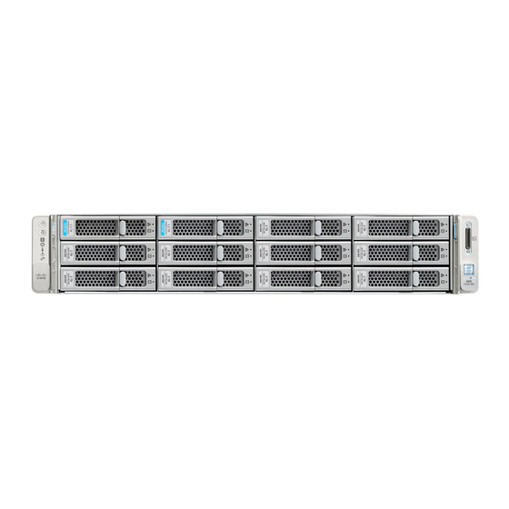
- Page 5 The following figure shows the front panel features of the small form-factor (SFF) drive, 8-drive version of the server (UCSC-C240-M5S). For definitions of LED states, see Front-Panel LEDs, on page Figure 2: Cisco UCS C240 M5 Server (SFF Drives, 8-Drive) Front Panel Temperature status LED UCSC-C240-M5S: Drive bays 1—8 support SAS/SATA drives.
- Page 6 KVM connector (used with KVM cable that provides one DB-15 VGA, one DB-9 serial, and two USB connectors) Cisco UCS C240 M5 Server (LFF Drives, 12-Drive) Front Panel Features The following figure shows the front panel features of the large form-factor (LFF) drive version of the server (UCSC-C240-M5L).
- Page 7 The rear panel features are the same for all versions of the server. For definitions of LED states, see Rear-Panel LEDs, on page Figure 4: Cisco UCS C240 M5 Server Rear Panel PCIe riser 1 (PCIe slot 1, 2, 3), with the following USB 3.0 ports (two) options: •...
- Page 8 1-Gb Ethernet dedicated management port Power Specifications, on page 122 for specifications and supported options. Threaded holes for dual-hole grounding lug. Serial port (RJ-45 connector) Modular LAN-on-motherboard (mLOM) card slot (x16) Rear unit identification button/LED Cisco UCS C240 M5 Server Installation and Service Guide...
- Page 9 This topic shows the locations of the field-replaceable components and service-related items. The view in the following figure shows the server with the top cover removed. Figure 5: Cisco UCS C240 M5 Server, Serviceable Component Locations Front-loading drive bays. Rear-drive backplane assembly...
-
Page 10: Summary Of Server Features
Cisco UCS Servers Technical Specifications Sheets (scroll down to Technical Specifications). Summary of Server Features The following table lists a summary of server features. Feature Description Chassis Two rack-unit (2RU) chassis Cisco UCS C240 M5 Server Installation and Service Guide... - Page 11 Baseboard management BMC, running Cisco Integrated Management Controller (Cisco IMC) firmware. Depending on your Cisco IMC settings, Cisco IMC can be accessed through the 1-Gb dedicated management port, the 1-Gb/10-Gb Ethernet LAN ports, or a Cisco virtual interface card. Network and management I/O Rear panel: •...
- Page 12 Six horizontal PCIe expansion slots on two PCIe riser assemblies. PCIe Slot Specifications, on page 95 for specifications of the slots. InfiniBand The PCIe bus slots in this server support the InfiniBand architecture. Cisco UCS C240 M5 Server Installation and Service Guide...
- Page 13 • ◦ ◦ ◦ • Cisco UCS C240 M5 (UCSC-C240-M5S)—SFF drives, with 8-drive backplane and DVD drive option. ◦Front-loading drive bays 1—8 support 2.5-inch SAS/SATA drives. ◦ Optionally, front-loading drive bays 1 and 2 support 2.5-inch NVMe SSDs. ◦ Optionally, the two rear-loading drive bays support up to two 2.5-inch SAS/SATA drives;...
- Page 14 RAID backup The server has a mounting bracket on the removable air baffle for one supercap unit that is used with the Cisco modular RAID controller card. Integrated video Integrated VGA video. Cisco UCS C240 M5 Server Installation and Service Guide...
-
Page 15: Table Of Contents
This section contains the following topics: Installation Warnings and Guidelines Note Before you install, operate, or service a server, review the Regulatory Compliance and Safety Information for Cisco UCS C-Series Servers for important safety information. Cisco UCS C240 M5 Server Installation and Service Guide... - Page 16 No additional spacing between the servers is required when you mount the units using rail kits. Cisco UCS C240 M5 Server Installation and Service Guide...
-
Page 17: Rack Requirements
Avoid uninterruptible power supply (UPS) types that use ferroresonant technology. These UPS types can Caution become unstable with systems such as the Cisco UCS, which can have substantial current draw fluctuations from fluctuating data traffic patterns. When you are installing a server, use the following guidelines: •... -
Page 18: Installing The Server In A Rack
Open the front securing plate on both slide-rail assemblies. The front end of the slide-rail assembly has a spring-loaded securing plate that must be open before you can insert the mounting pegs into the rack-post holes. Cisco UCS C240 M5 Server Installation and Service Guide... - Page 19 Align the rear ends of the inner rails that are attached to the server sides with the front ends of the empty slide rails on the rack. Cisco UCS C240 M5 Server Installation and Service Guide...
- Page 20 The screw threads into the static part of the rail on the rack post and prevents the server from being pulled out. Repeat for the opposite slam latch. Cisco UCS C240 M5 Server Installation and Service Guide...
- Page 21 CMA tab on arm closest to the server attaches to Rear of server end of inner slide rail attached to server. Cisco UCS C240 M5 Server Installation and Service Guide...
- Page 22 180 degrees so that it points toward the rear of the server. Figure 10: Reversing the CMA CMA tab on end of width-adjustment slider Metal button on outside of tab Cisco UCS C240 M5 Server Installation and Service Guide...
-
Page 23: Initial Server Setup
There are two methods for connecting to the system for initial setup: • Local setup—Use this procedure if you want to connect a keyboard and monitor directly to the system for setup. This procedure can use a KVM cable (Cisco PID N20-BKVM) or the ports on the rear of the server. - Page 24 Connect a USB keyboard and VGA monitor to the server using one of the following methods: • Connect an optional KVM cable (Cisco PID N20-BKVM) to the KVM connector on the front panel. Connect your USB keyboard and VGA monitor to the KVM cable.
- Page 25 Allow your preconfigured DHCP server to assign an IP address to the server node. Step 4 Use the assigned IP address to access and log in to the Cisco IMC for the server node. Consult with your DHCP server administrator to determine the IP address.
- Page 26 Setting Up the System With the Cisco IMC Configuration Utility In this NIC mode, DHCP replies are returned to both the shared LOM ports and the Cisco card ports. If the system determines that the Cisco card connection is not getting its IP address from a Cisco UCS Manager system because the server is in standalone mode, further DHCP requests from the Cisco card are disabled.
-
Page 27: Nic Mode And Nic Redundancy Settings
What to Do Next Use a browser and the IP address of the Cisco IMC to connect to the Cisco IMC management interface. The IP address is based upon the settings that you made (either a static address or the address assigned by your DHCP server). - Page 28 Active-Active NIC redundancy setting in the following step. In this NIC mode, DHCP replies are returned to both the shared LOM ports and the Cisco card ports. If the system determines that the Cisco card connection is not getting its IP address from a Cisco UCS Manager system because the server is in standalone mode, further DHCP requests from the Cisco card are disabled.
-
Page 29: Updating The Bios And Cisco Imc Firmware
When you upgrade the BIOS firmware, you must also upgrade the Cisco IMC firmware to the same version Caution or the server does not boot. Do not power off the server until the BIOS and Cisco IMC firmware are matching or the server does not boot. -
Page 30: Smart Access Usb
• This feature has the following requirements: ◦ A serial cable connection, which can use either the RJ-45 serial connector on the server rear panel, or a DB-9 connection when using the KVM cable (Cisco PID N20-BKVM) on the front-panel KVM console connector. - Page 31 ◦ Disabled: the front-panel USB device is connected to the host. • In a case where no management network is available to connect remotely to Cisco IMC, a Device Firmware Update (DFU) shell over serial cable can be used to generate and download technical support files to the USB device that is attached to front panel USB port.
- Page 32 Installing the Server Smart Access USB Cisco UCS C240 M5 Server Installation and Service Guide...
-
Page 33: Status Leds And Buttons
Preparing For Component Installation, page 39 • Removing and Replacing Components, page 43 • Service Headers and Jumpers, page 112 Status LEDs and Buttons This section contains information for interpreting LED states. Cisco UCS C240 M5 Server Installation and Service Guide... - Page 34 • Off—There is no hard drive in the hard drive tray (no access, no fault). • Green—The hard drive is ready. • Green, blinking—The hard drive is reading or writing data. Cisco UCS C240 M5 Server Installation and Service Guide...
- Page 35 Power button/LED • Off—There is no AC power to the server. • Amber—The server is in standby power mode. Power is supplied only to the Cisco IMC and some motherboard functions. • Green—The server is in main power mode. Power is supplied to all server components.
- Page 36 • Off—The Ethernet LOM port link is idle. • Green—One or more Ethernet LOM ports are link-active, but there is no activity. • Green, blinking—One or more Ethernet LOM ports are link-active, with activity. Cisco UCS C240 M5 Server Installation and Service Guide...
- Page 37 • Green—Link speed is 10 Gbps. 1-Gb/10-Gb Ethernet link status (on both LAN1 and LAN2) • Off—No link is present. • Green—Link is active. • Green, blinking—Traffic is present on the active link. Cisco UCS C240 M5 Server Installation and Service Guide...
- Page 38 • Green, solid—12 V main power on; 12 V standby power • Amber, blinking—Warning threshold detected but 12 V main power on. • Amber, solid—Critical error detected; 12 V main power off (for example, over-current, over-voltage, or over-temperature failure). Cisco UCS C240 M5 Server Installation and Service Guide...
- Page 39 • Amber—The drive has failed. • Amber, blinking—A drive Locate command has been issued in the software. NVMe SSD activity • Off—No drive activity. NVMe • Green, blinking—There is drive activity. Cisco UCS C240 M5 Server Installation and Service Guide...
-
Page 40: Internal Diagnostic Leds
CPU fault LEDs (one behind each CPU socket on the motherboard). These LEDs operate only when the server is in standby power mode. • Amber—CPU has a fault. • Off—CPU is OK. Cisco UCS C240 M5 Server Installation and Service Guide... -
Page 41: Chapter:
• Graceful shutdown—Press and release the Power button. The operating system performs a graceful shutdown and the server goes to standby mode, which is indicated by an amber Power button/LED. Cisco UCS C240 M5 Server Installation and Service Guide... - Page 42 The operating system performs a graceful shutdown and the server goes to standby mode, which is indicated by an amber Power button/LED. Step 3 If a service procedure instructs you to completely remove power from the server, disconnect all power cords from the power supplies in the server. Cisco UCS C240 M5 Server Installation and Service Guide...
-
Page 43: Removing The Server Top Cover
If a service procedure instructs you to completely remove power from the server, disconnect all power cords from the power supplies in the server. Removing the Server Top Cover Step 1 Remove the top cover: Cisco UCS C240 M5 Server Installation and Service Guide... - Page 44 If desired, lock the latch by using a screwdriver to turn the lock 90-degrees clockwise. Figure 14: Removing the Top Cover Cover latch Serial number label location Cover lock Cisco UCS C240 M5 Server Installation and Service Guide...
-
Page 45: Removing And Replacing Components
Statement 1029 When handling server components, handle them only by carrier edges and use an electrostatic discharge Caution (ESD) wrist-strap or other grounding device to avoid damage. Cisco UCS C240 M5 Server Installation and Service Guide... - Page 46 This topic shows the locations of the field-replaceable components and service-related items. The view in the following figure shows the server with the top cover removed. Figure 15: Cisco UCS C240 M5 Server, Serviceable Component Locations Front-loading drive bays. Rear-drive backplane assembly...
- Page 47 • 2B: One connector for rear NVMe SSDs. • 2C: One connector for rear NVMe SSDs plus one connector for front-loading NVMe SSDs • Rear-drive fan module RTC battery, vertical socket Cisco UCS C240 M5 Server Installation and Service Guide...
- Page 48 • ◦ ◦ • Cisco UCS C240 M5 (UCSC-C240-M5S)—SFF drives, with 8-drive backplane and DVD drive option. ◦Front-loading drive bays 1—8 support 2.5-inch SAS/SATA drives. ◦ Optionally, front-loading drive bays 1 and 2 support 2.5-inch NVMe SSDs. • Cisco UCS C240 M5 (UCSC-C240-M5L)—Large form-factor (LFF) drives, with 12-drive backplane.
- Page 49 • You must boot 4K sector format drives in UEFI mode, not legacy mode. See the procedures in this section. • Do not configure 4K sector format and 512-byte sector format drives as part of the same RAID volume. Cisco UCS C240 M5 Server Installation and Service Guide...
- Page 50 Under Boot Option Priorities, verify that the OS you installed is listed as your Boot Option #1. Setting Up UEFI Mode Booting in the Cisco IMC GUI Step 1 Use a web browser and the IP address of the server to log into the Cisco IMC GUI management interface. Step 2 Navigate to Server > BIOS.
- Page 51 Place a new drive in the empty drive tray and install the four drive-tray screws. b) With the ejector lever on the drive tray open, insert the drive tray into the empty drive bay. Cisco UCS C240 M5 Server Installation and Service Guide...
- Page 52 Push the tray into the slot until it touches the backplane, and then close the ejector lever to lock the drive in place. Figure 19: Replacing a Drive in a Drive Tray Ejector lever Drive tray screws (two on each side) Release button Drive removed from drive tray Cisco UCS C240 M5 Server Installation and Service Guide...
- Page 53 (virtual drive) that contains a mix of hard drives and SSDs. That is, when you create a logical volume, it must contain all SAS/SATA hard drives or all SAS/SATA SSDs. Cisco UCS C240 M5 Server Installation and Service Guide...
- Page 54 Place a new drive in the empty drive tray and install the four drive-tray screws. b) With the ejector lever on the drive tray open, insert the drive tray into the empty drive bay. Cisco UCS C240 M5 Server Installation and Service Guide...
- Page 55 Drive tray screws (two on each side) Release button Drive removed from drive tray Replacing Front-Loading NVMe SSDs This section is for replacing 2.5-inch or 3.5-inch form-factor NVMe solid-state drives (SSDs) in front-panel drive bays. Cisco UCS C240 M5 Server Installation and Service Guide...
- Page 56 Setting Up UEFI Mode Booting in the BIOS Setup Utility, on page 48 Setting Up UEFI Mode Booting in the Cisco IMC GUI, on page • You cannot control NVMe PCIe SSDs with a SAS RAID controller because NVMe SSDs interface with the server via the PCIe bus.
- Page 57 Save your changes and exit the utility. Enabling Hot-Plug Support Using the Cisco IMC GUI Step 1 Use a browser to log in to the Cisco IMC GUI for the server. Step 2 Navigate to Compute > BIOS > Advanced > PCI Configuration.
- Page 58 Observe the drive-tray LED and wait until it returns to solid green before accessing the drive: • Off—The drive is not in use. • Green, blinking—the driver is initializing following hot-plug insertion. • Green—The drive is in use and functioning properly. Cisco UCS C240 M5 Server Installation and Service Guide...
- Page 59 Installing Riser 2C Kit For Front-Loading NVMe SSDs The front-loading NVMe SSDs interface with the server via the PCIe bus. A PCIe cable connects the front-panel drive backplane to PCIe riser 2C. Cisco UCS C240 M5 Server Installation and Service Guide...
- Page 60 • The red line represents the cable path from riser 2C to the front-drive backplane. • The blue line represents the cable path from riser 2C to the optional rear-drive backplane. Figure 22: PCIe Cabling From PCIe Riser 2 to Drive Backplanes Cisco UCS C240 M5 Server Installation and Service Guide...
- Page 61 ◦24-drive server—rear bays are numbered bays 25 and 26. • When populating drives, add drives to the lowest-numbered bays first. • Keep an empty drive blanking tray in any unused bays to ensure proper airflow. Cisco UCS C240 M5 Server Installation and Service Guide...
- Page 62 Setting Up UEFI Mode Booting in the BIOS Setup Utility, on page 48 Setting Up UEFI Mode Booting in the Cisco IMC GUI, on page • You cannot control NVMe PCIe SSDs with a SAS RAID controller because NVMe SSDs interface with the server via the PCIe bus.
- Page 63 Observe the drive-tray LED and wait until it returns to solid green before accessing the drive: • Off—The drive is not in use. • Green, blinking—the driver is initializing following hot-plug insertion. • Green—The drive is in use and functioning properly. Cisco UCS C240 M5 Server Installation and Service Guide...
- Page 64 Installing Riser 2B or 2C Kit For Rear-Loading NVMe SSDs The rear-loading NVMe SSDs interface with the server via the PCIe bus. A PCIe cable connects the rear drive backplane to PCIe riser 2B or 2C. Cisco UCS C240 M5 Server Installation and Service Guide...
- Page 65 • The blue line represents the cable path from riser 2B or 2C to the optional rear drive backplane. • The red line represents the cable path from riser 2C (only) to the front drive backplane. Figure 24: PCIe Cabling From PCIe Riser 2 to Drive Backplanes Cisco UCS C240 M5 Server Installation and Service Guide...
- Page 66 Step 6 Replace the top cover to the server. Step 7 Replace the server in the rack, replace cables, and then fully power on the server by pressing the Power button. Cisco UCS C240 M5 Server Installation and Service Guide...
- Page 67 Replace the top cover to the server. Step 8 Replace the server in the rack, replace cables, and then fully power on the server by pressing the Power button. Figure 25: Rear Drive Backplane Fan Cisco UCS C240 M5 Server Installation and Service Guide...
- Page 68 Remove an existing HHHL form-factor NVME SSD (or a blank filler panel) from the PCIe riser: a) Shut down and remove power from the server as described in Shutting Down and Removing Power From the Server, on page Cisco UCS C240 M5 Server Installation and Service Guide...
- Page 69 Position the PCIe riser over its socket on the motherboard and over the chassis alignment channels. g) Carefully push down on both ends of the PCIe riser to fully engage its connector with the sockets on the motherboard. h) Replace the top cover to the server. Cisco UCS C240 M5 Server Installation and Service Guide...
-
Page 70: Replacing Fan Modules
There is a fault LED on the top of each fan module. This LED lights green when the fan is correctly seated and is operating OK. The LED lights amber when the fan has a fault or is not correctly seated. Cisco UCS C240 M5 Server Installation and Service Guide... - Page 71 Replace the server in the rack, replace cables, and then fully power on the server by pressing the Power button. Figure 27: Top View of Fan Module Fan module release latches Fan module fault LED Cisco UCS C240 M5 Server Installation and Service Guide...
- Page 72 Caution Caution Cisco does not support third-party DIMMs. Using non-Cisco DIMMs in the server might result in system problems or damage to the motherboard. To ensure the best server performance, it is important that you are familiar with memory performance Note guidelines and population rules before you install or replace DIMMs.
- Page 73 The CPUs in the server support memory mirroring only when an even number of channels are populated with DIMMs. If one or three channels are populated with DIMMs, memory mirroring is automatically disabled. Cisco UCS C240 M5 Server Installation and Service Guide...
-
Page 74: Replacing Dimms
• Tools Required For CPU Replacement, on page 73 • Replacing a CPU and Heatsink, on page 73 • Additional CPU-Related Parts to Order with RMA Replacement Motherboards, on page 80 Cisco UCS C240 M5 Server Installation and Service Guide... -
Page 75: Cpu Configuration Rules
• Heatsink cleaning kit—Supplied with replacement CPU. Orderable separately as Cisco PID UCSX-HSCK=. • Thermal interface material (TIM)—Syringe supplied with replacement CPU. Use only if you are reusing your existing heatsink (new heatsinks have a pre-applied pad of TIM). Orderable separately as Cisco PID UCS-CPU-TIM=. See also... - Page 76 4, 3, 2, 1. e) Lift straight up on the CPU/heatsink assembly and set it heatsink-down on an antistatic surface. Figure 29: Removing the CPU/Heatsink Assembly Cisco UCS C240 M5 Server Installation and Service Guide...
- Page 77 Note the thermal-interface material (TIM) breaker location. TIM BREAKER is stamped on the CPU carrier next to a small slot. Figure 30: Separating the CPU Assembly From the Heatsink CPU carrier CPU-carrier inner-latch nearest to the TIM breaker slot #1 flat-head screwdriver inserted into TIM breaker slot Cisco UCS C240 M5 Server Installation and Service Guide...
- Page 78 If the CPU assembly and CPU assembly tool become separated, note the alignment features for correct orientation. The pin 1 triangle on the CPU carrier must be aligned with the angled corner on the CPU assembly tool. Cisco UCS C240 M5 Server Installation and Service Guide...
- Page 79 CPU assembly (CPU in plastic carrier frame) Triangle cut into plastic carrier (pin 1 alignment feature) Heatsink Angled corner on CPU assembly tool (pin 1 alignment feature) Step 4 Apply new TIM to the heatsink: Cisco UCS C240 M5 Server Installation and Service Guide...
- Page 80 Install the CPU/heatsink assembly to the server: a) Lift the heatsink with attached CPU assembly from the CPU assembly tool. b) Align the assembly over the CPU socket on the motherboard. Cisco UCS C240 M5 Server Installation and Service Guide...
- Page 81 Set the heatsink with CPU assembly down onto the CPU socket. d) Use the T-30 Torx driver that is supplied with the replacement CPU to tighten the four captive nuts that secure the heatsink to the motherboard standoffs. Cisco UCS C240 M5 Server Installation and Service Guide...
- Page 82 Additional CPU-Related Parts to Order with RMA Replacement Motherboards When a return material authorization (RMA) of the motherboard or CPU is done on a Cisco UCS C-Series server, additional parts might not be included with the CPU or motherboard spare bill of materials (BOM).
- Page 83 Position carrier over socket, with the carrier's connector facing down. Two alignment pegs must match with two holes on the carrier. b) Gently push down the socket end of the carrier so that the two pegs go through the two holes on the carrier. Cisco UCS C240 M5 Server Installation and Service Guide...
- Page 84 Population Rules For Mini-Storage SD Cards • You can use one or two SD cards in the carrier. • Dual SD cards can be configured in a RAID 1 array through the Cisco IMC interface. Cisco UCS C240 M5 Server Installation and Service Guide...
- Page 85 Install a new M.2 SSD: a) Insert the new M.2 SSD connector-end into the socket on the carrier with its label side facing up. b) Press the M.2 SSD flat against the carrier. Cisco UCS C240 M5 Server Installation and Service Guide...
- Page 86 While holding the retainer on the plastic cover open with your fingertip, align the new Micro SD card with the socket. b) Gently push down on the card until it clicks and locks in place in the socket. c) Replace the top cover to the server. Cisco UCS C240 M5 Server Installation and Service Guide...
- Page 87 Step 1 Remove an existing internal USB drive: a) Shut down and remove power from the server as described in Shutting Down and Removing Power From the Server, on page Cisco UCS C240 M5 Server Installation and Service Guide...
- Page 88 Replace the server in the rack, replace cables, and then fully power on the server by pressing the Power button. Figure 36: Location of Internal USB Port <ILLO PENDING> Location of vertical USB socket on motherboard Cisco UCS C240 M5 Server Installation and Service Guide...
-
Page 89: Replacing The Rtc Battery
The real-time clock (RTC) battery retains system settings when the server is disconnected from power. The battery type is CR2032. Cisco supports the industry-standard CR2032 battery, which can be ordered from Cisco (PID N20-MBLIBATT) or purchased from most electronic stores. -
Page 90: Replacing Power Supplies
• See also Rear-Panel LEDs, on page 35 for information about the power supply LEDs. This section includes procedures for replacing AC and DC power supply units. Cisco UCS C240 M5 Server Installation and Service Guide... - Page 91 Only if you shut down the server, press the Power button to boot the server to main power mode. Figure 38: Replacing AC Power Supplies Power supply release lever Power supply handle Cisco UCS C240 M5 Server Installation and Service Guide...
- Page 92 Pull the power supply out of the bay. Step 2 Install a new DC power supply: a) Grasp the power supply handle and insert the new power supply into the empty bay. Cisco UCS C240 M5 Server Installation and Service Guide...
- Page 93 Warning Statement 1022 Warning This product requires short-circuit (overcurrent) protection, to be provided as part of the building installation. Install only in accordance with national and local wiring regulations. Statement 1045 Cisco UCS C240 M5 Server Installation and Service Guide...
- Page 94 Step 1 Turn off the DC power source from your facility’s circuit breaker to avoid electric shock hazard. The required DC input cable is Cisco part CAB-48DC-40A-8AWG. This 3-meter cable has a 3-pin connector Note on one end that is keyed to the DC input socket on the power supply. The other end of the cable has no connector so that you can wire it to your facility’s DC power.
-
Page 95: Replacing A Pcie Riser
If you removed a card from the old PCIe riser, install the card to the new riser. See Replacing a PCIe Card, on page b) Position the PCIe riser over its socket on the motherboard and over its alignment slots in the chassis. Cisco UCS C240 M5 Server Installation and Service Guide... -
Page 96: Replacing A Pcie Card
Replacing a PCIe Card Note Cisco supports all PCIe cards qualified and sold by Cisco. PCIe cards not qualified or sold by Cisco are the responsibility of the customer. Although Cisco will always stand behind and support the C-Series rack-mount servers, customers using standard, off-the-shelf, third-party cards must go to the third-party card vendor for support if any issue with that particular card occurs. - Page 97 Gen-3 x16 x24 connector Full length Full height Gen-3 x8 x16 connector Full length Full hight Micro SD card One socket for Micro SD card on the top of the riser. slot Cisco UCS C240 M5 Server Installation and Service Guide...
- Page 98 Table 8: PCIe Riser 2B (UCSC-PCI-2B-C240M5) PCIe Expansion Slots Slot Number Electrical Lane Connector Maximum Card Card Height NCSI Support GPU Card Width Length Length (Rear Panel Support Opening) Gen-3 x8 x24 connector ¾ length Full height Cisco UCS C240 M5 Server Installation and Service Guide...
- Page 99 6 NCSI is supported in only one slot at a time. Note Replacing a PCIe Card If you are installing a Cisco UCS Virtual Interface Card, there are prerequisite considerations. See Cisco Note Virtual Interface Card (VIC) Considerations, on page RAID controller cards install into a dedicated motherboard socket.
- Page 100 Swing the hinged securing plate closed on the bottom of the riser. Ensure that the clip on the plate clicks into the locked position. e) Position the PCIe riser over its socket on the motherboard and over the chassis alignment channels. Cisco UCS C240 M5 Server Installation and Service Guide...
- Page 101 Figure 43: PCIe Riser Card Securing Mechanisms Release latch on hinged securing plate Hinged card-tab retainer Hinged securing plate Cisco Virtual Interface Card (VIC) Considerations This section describes VIC card support and special considerations for this server. Cisco UCS C240 M5 Server Installation and Service Guide...
-
Page 102: Replacing An Mlom Card
Maintaining the Server Replacing an mLOM Card If you use the Cisco Card NIC mode, you must also make a VIC Slot setting that matches where your VIC Note is installed. The options are Riser1, Riser2, and Flex-LOM. See NIC Mode and NIC Redundancy Settings, on page 25 for more information about NIC modes. - Page 103 Position of mLOM card thumbscrew Replacing a SAS Storage Controller Card (RAID or HBA) For hardware-based storage control, the server can use a Cisco modular SAS RAID controller or SAS HBA that plugs into a dedicated, vertical socket on the motherboard.
- Page 104 Host Upgrade Utility (HUU) for your firmware release to bring it to a compatible level. See the HUU guide for your Cisco IMC release for instructions on downloading and using the utility to bring server components to compatible levels: Guides.
- Page 105 This server supports installation of one supercap unit. The unit mounts to a bracket on the removable air baffle. The supercap provides approximately three years of backup for the disk write-back cache DRAM in the case of a sudden power loss by offloading the cache to the NAND flash. Cisco UCS C240 M5 Server Installation and Service Guide...
- Page 106 Push aside the black plastic tab on the air baffle and set the supercap into the bracket. Relax the tab so that it closes over the top edge of the supercap. Cisco UCS C240 M5 Server Installation and Service Guide...
- Page 107 For software-based storage control that uses the server's embedded SATA controller to control front-loading drives, the server requires a SATA interposer card that plugs into a dedicated socket on the motherboard (the same socket used for SAS storage controllers). Cisco UCS C240 M5 Server Installation and Service Guide...
- Page 108 Fully close the blue ejector lever on the card to lock the card into the socket. d) Connect PCIe cables to the new card. If this is a first-time installation, see Storage Controller Cable Connectors and Backplanes, on page 133 for cabling instructions. Cisco UCS C240 M5 Server Installation and Service Guide...
- Page 109 Step 1 Prepare the server for component installation: a) Shut down and remove power from the server as described in Shutting Down and Removing Power From the Server, on page Cisco UCS C240 M5 Server Installation and Service Guide...
- Page 110 Step 5 Replace the server in the rack, replace cables, and then fully power on the server by pressing the Power button. Figure 48: Replacing a Chassis Intrusion Switch Intrusion switch location Cisco UCS C240 M5 Server Installation and Service Guide...
- Page 111 Slide the server out the front of the rack far enough so that you can remove the top cover. You might have to detach cables from the rear panel to provide clearance. If you cannot safely view and access the component, remove the server from the Caution rack. Cisco UCS C240 M5 Server Installation and Service Guide...
- Page 112 Replace the server in the rack, replace cables, and then fully power on the server by pressing the Power button. Step 7 Continue with Enabling the TPM in the BIOS, on page 111. Figure 49: Location of the TPM Socket TPM socket location on motherboard, below PCIe riser 2 Cisco UCS C240 M5 Server Installation and Service Guide...
- Page 113 Verify that the following items are listed as Enabled: • VT-d Support (default is Enabled) • VT Support (default is Enabled) • TPM Support • TPM State d) Do one of the following: Cisco UCS C240 M5 Server Installation and Service Guide...
-
Page 114: Service Headers And Jumpers
Using the Boot Alternate Cisco IMC Image Header (J39, Pins 1 - 2), on page 117 • Using the Reset Cisco IMC Password to Default Header (J39, Pins 3 - 4), on page 118 Cisco UCS C240 M5 Server Installation and Service Guide... - Page 115 Using the Clear CMOS Header (J38, Pins 9 - 10) • Using the Reset Cisco IMC to Defaults Header (J39, Pins 5 - 6), on page 118 Figure 50: Location of Service Header Blocks J38 and J39 Location of header block J38...
- Page 116 • If it is a non-BootBlock corruption, a message similar to the following is displayed: ****BIOS FLASH IMAGE CORRUPTED**** Flash a valid BIOS capsule file using Cisco IMC WebGUI or CLI interface. IF Cisco IMC INTERFACE IS NOT AVAILABLE, FOLLOW THE STEPS MENTIONED BELOW.
- Page 117 Step 6 Wait for server to complete the BIOS update, and then remove the USB drive from the server. During the BIOS update, Cisco IMC shuts down the server and the screen goes blank for about 10 minutes. Do Note not unplug the power cords during this update.
- Page 118 Step 10 Wait for server to complete the BIOS update, and then remove the USB drive from the server. During the BIOS update, Cisco IMC shuts down the server and the screen goes blank for about 10 minutes. Do Note not unplug the power cords during this update.
- Page 119 CIMC will boot from alternate image on next reboot or input power cycle. If you do not remove the jumper, the server will boot from an alternate Cisco IMC image every time that you Note power cycle the server or reboot Cisco IMC.
- Page 120 'Reset to default CIMC password' debug functionality is enabled. On input power cycle, CIMC password will be reset to defaults. If you do not remove the jumper, the server will reset the Cisco IMC password to the default every time that Note you power cycle the server.
- Page 121 'CIMC reset to factory defaults' debug functionality is enabled. On input power cycle, CIMC will be reset to factory defaults. If you do not remove the jumper, the server will reset the Cisco IMC to the default settings every time that you Note power cycle the server.
- Page 122 Maintaining the Server Using the Reset Cisco IMC to Defaults Header (J39, Pins 5 - 6) Cisco UCS C240 M5 Server Installation and Service Guide...
- Page 123 Server with slide rail: 31.0 in (787.4 mm) Maximum weight (fully loaded chassis) SFF 8-drive: 45.5 lb. (20.6 Kg) SFF 24-drive: 57.5 lb. (26.1 Kg) LFF 12-drive: 64.0 lb. (29.0 Kg) Cisco UCS C240 M5 Server Installation and Service Guide...
-
Page 124: Environmental Specifications
Power Specifications Do not mix power supply types or wattages in the server. Both power supplies must be identical. Note You can get more specific power information for your exact server configuration by using the Cisco UCS Power Calculator: http://ucspowercalc.cisco.com The power specifications for the supported power supply options are listed in the following sections. - Page 125 Server Specifications Power Specifications 1050 W AC Power Supply This section lists the specifications for each 1050 W AC power supply (Cisco part number UCSC-PSU1-1050W). Table 13: 1050 W AC Specifications Description Specification AC Input Voltage Nominal range: 100–120 VAC, 200–240 VAC (Range: 90–132 VAC, 180–264 VAC)
- Page 126 Climate Savers Platinum Efficiency (80Plus Platinum certified) Form factor RSP2 Input connector IEC320 C14 1050 W DC Power Supply This section lists the specifications for each 1050 W DC power supply (Cisco part number UCSC-PSUV2-1050DC). Table 15: 1050 W DC Specifications Description Specification DC Input Voltage...
-
Page 127: Power Cord Specifications
CAB-C13-C14-AC AC power cord, 10 A; C13 to C14, recessed receptacle CAB-250V-10A-AR AC power cord, 250 V, 10 A Argentina CAB-C13-C14-2M-JP AC Power Cord, C13 to C14 Japan PSE Mark Cisco UCS C240 M5 Server Installation and Service Guide... - Page 128 North America CAB-250V-10A-ID AC power Cord, 250 V, 10 A, India CAB-9K10A-SW AC power cord, 250 V, 10 A, MP232 plug Switzerland CAB-250V-10A-BR AC power Cord, 250 V, 10 A Brazil Cisco UCS C240 M5 Server Installation and Service Guide...
- Page 129 AC power cord, NEMA L6-20 to C13 connectors CAB-9K10A-IT AC power cord, 250 V, 10 A, CEI 23-16/VII plug Italy R2XX-DMYMPWRCORD No power cord; PID option for ordering server with no power cord Cisco UCS C240 M5 Server Installation and Service Guide...
- Page 130 Server Specifications Power Cord Specifications Cisco UCS C240 M5 Server Installation and Service Guide...
- Page 131 Storage Controller Card Firmware Compatibility, page 131 • RAID Backup (Supercap), page 131 • Write-Cache Policy for Cisco 12G SAS Modular RAID Controllers, page 132 • Mixing Drive Types in RAID Groups, page 132 • RAID Controller Migration, page 133 •...
- Page 132 UCSC-RAID-M5HD drive backplanes. • SFF 24-drives Includes 4-GB cache; (UCSC-C240-M5SX): controls up to 26 drives 24 front-loading, plus 2 rear-loading SAS/SATA drives Cisco UCS C240 M5 Server Installation and Service Guide...
- Page 133 Host Upgrade Utility (HUU) for your firmware release to bring it to a compatible level. See the HUU guide for your Cisco IMC release for instructions on downloading and using the utility to bring server components to compatible levels: Guides.
-
Page 134: Mixing Drive Types In Raid Groups
The write policy can be set to Write Back, if preferred. You can set the write policy using the following methods: • For standalone servers, use the Cisco IMC interface to set Virtual Drive Properties > Write Policy. See the “Managing Storage Adapters” section in your Cisco IMC Configuration Guide. -
Page 135: Raid Controller Migration
Embedded RAID is disabled in the BIOS. Storage Controller Cable Connectors and Backplanes This section describes cabling for the storage controllers and backplanes. The SAS/SATA cables are factory-installed and are used for all supported internal controllers. Cisco UCS C240 M5 Server Installation and Service Guide... - Page 136 Figure 51: SATA Interposer Cabling (SFF, 8-Drive Version Only) Cisco 12G Modular SAS RAID Controller or HBA For Up To 16 Drives (UCSC-RAID-M5 or UCSC-SAS-M5) The drive support differs by server version, as described in the following sections. These controllers are supported only in these server versions: •...
- Page 137 2 Connect SAS/SATA cable A2 from the A2 card connector to the A2 front backplane connector. 3 Connect SAS/SATA cable B2 from the B2 card connector to the B2 front backplane connector. Cisco UCS C240 M5 Server Installation and Service Guide...
- Page 138 4 Optional for rear drives: Connect SAS/SATA cable B1 from the B1 card connector to the rear backplane connector. Figure 53: LFF, 12-Drive UCSC-C240-M5L Cabling With UCSC-RAID-M5 Cisco 12G Modular SAS RAID Controller or HBA For Up To 26 Drives (UCSC-RAID-M5HD or UCSC-SAS-M5HD) This controller is supported only in this server version: • SFF 24-Drives UCSC-C240-M5SX This HW RAID or HBA option can control up to 24 front-loading SAS/SATA drives in this server version, plus 2 rear-loading SAS/SATA drives.
-
Page 139: Embedded Sata Raid Controller
VMware ESX/ESXi or any other virtualized environments are not supported for use with the embedded MegaRAID controller. Hypervisors such as Hyper-V, Xen, or KVM are also not supported for use with the embedded MegaRAID controller. Cisco UCS C240 M5 Server Installation and Service Guide... -
Page 140: Embedded Sata Raid Controller Considerations
Migrations from software RAID to hardware RAID are supported only before there is data on the front-loading drives, or when there are no drives in the server. Cisco UCS C240 M5 Server Installation and Service Guide... - Page 141 Embedded SATA RAID: Two SATA Controllers The embedded RAID platform controller hub (PCH) is split into two controllers: primary SATA (pSATA) and secondary SATA (sSATA). These two controllers are seen as separate RAID controllers in the Cisco IMC interface and are configurable separately.
-
Page 142: Installing Lsi Megasr Drivers For Windows And Linux
This section explains how to install the LSI MegaSR drivers for the following supported operating systems: • Microsoft Windows Server • Red Hat Enterprise Linux (RHEL) • SUSE Linux Enterprise Server (SLES) Cisco UCS C240 M5 Server Installation and Service Guide... - Page 143 • For pSATA, select LSI Software RAID Configuration Utility (SATA) • For sSATA, select LSI Software RAID Configuration Utility (sSATA) Step 1 Download the Cisco UCS C-Series drivers’ ISO, as described in Downloading the MegaSR Drivers, on page 141. Step 2 Prepare the drivers on a USB thumb drive: a) Burn the ISO image to a disk.
- Page 144 Windows installation disk into the DVD drive. Skip to Step 6. • To install from remote ISO, log in to the server’s Cisco IMC interface and continue with the next step. Step 4 Launch a Virtual KVM console window and click the Virtual Media tab.
- Page 145 , which is the boot image for the embedded dud-[driver version].img MegaRAID stack. The LSI MegaSR drivers that Cisco provides for RHEL and SLES are for the original GA versions of Note those distributions. The drivers do not support updates to those OS kernels.
- Page 146 • To install from local media, connect an external USB DVD drive to the server and then insert the first RHEL installation disk into the drive. Then continue with Step 6. • To install from remote ISO, log in to the server’s Cisco IMC interface. Then continue with the next step. Step 4 Launch a Virtual KVM console window and click the Virtual Media tab.
- Page 147 To access the configuration utility, open the BIOS Setup Utility, go to the Advanced tab, and then choose the utility instance for the embedded controller: • For pSATA, select LSI Software RAID Configuration Utility (SATA) Cisco UCS C240 M5 Server Installation and Service Guide...
- Page 148 • To install from local media, connect an external USB DVD drive to the server and then insert the first SLES installation disk into the drive. Then continue with Step 6. • To install from remote ISO, log in to the server’s Cisco IMC interface. Then continue with the next step. Step 4 Launch a Virtual KVM console window and click the Virtual Media tab.
- Page 149 12Gb/s MegaRAID SAS Software User Guide, Version 2.8 • For embedded software MegaRAID and the utility that is accessed via the server BIOS (refer to Chapter 4)—Avago Technologies Embedded MegaRAID Software User Guide, Revison 2.1. Cisco UCS C240 M5 Server Installation and Service Guide...
- Page 150 Storage Controller Considerations For More RAID Utility Information Cisco UCS C240 M5 Server Installation and Service Guide...
- Page 151 3.1(1) NVIDIA Tesla P100 12GB 3.1(1) NVIDIA Tesla P100 16GB 3.1(1) AMD FirePro S7150 X2 3.1(1) GPU Card Configuration Rules Note the following rules when populating a server with GPU cards. Cisco UCS C240 M5 Server Installation and Service Guide...
- Page 152 • Do not mix different brands or models of GPU cards in the server. • You can install a GPU card and a Cisco UCS VIC in the same riser. When you install a GPU card in slot 2, NCSI support in riser 1 automatically moves to slot 1. When you install a GPU card in slot 5, NCSI support in riser 2 automatically moves to slot 4.
- Page 153 GPU Card Installation Installing a Double-Wide GPU Card • If the server is integrated with Cisco UCS Manager and is controlled by a service profile, this setting is enabled by default in the service profile when a GPU is present.
- Page 154 Connect the GPU power cable. The straight power cable connectors are color-coded. Connect the cable's black connector into the black connector on the GPU card and the cable's white connector into the white GPU POWER connector on the PCIe riser. Cisco UCS C240 M5 Server Installation and Service Guide...
- Page 155 Ensure that the latch release tab clicks and locks the latch in place. Figure 55: GPU Front Support Bracket Inserted to Securing latch on Air Baffle Front end of GPU card Lip on securing latch GPU front support bracket Securing latch release tab Cisco UCS C240 M5 Server Installation and Service Guide...
- Page 156 NVIDIA GRID License Server virtual appliance. The license is returned to the license server when the OS shuts down. Cisco UCS C240 M5 Server Installation and Service Guide...
- Page 157 Virtual GPUs for business desktop computing GRID Virtual Workstation Virtual GPUs for midrange workstation computing GRID Virtual Workstation – Extended Virtual GPUs for high-end workstation computing Workstation graphics on GPU pass-through Cisco UCS C240 M5 Server Installation and Service Guide...
- Page 158 • The hosting platform can be a physical or a virtual machine. NVIDIA recommends using a host that is dedicated only to running the License Server. • The hosting platform must run a supported Windows OS. Cisco UCS C240 M5 Server Installation and Service Guide...
- Page 159 Use your Linux package manager to install the tomcat and tomcat-webapps packages: a) Use the following command to install Tomcat: sudo yum install tomcat b) Enable the Tomcat service for automatic startup on boot: Cisco UCS C240 M5 Server Installation and Service Guide...
- Page 160 It is important to use the same Ethernet ID consistently to identify the server when generating licenses on Note NVIDIA’s Licensing Portal. NVIDIA recommends that you select one entry for a primary, non-removable Ethernet interface on the platform. Cisco UCS C240 M5 Server Installation and Service Guide...
- Page 161 Access the GRID License Server Management Interface in a browser. Step 2 In the left-side License Server panel, select Licensed Clients. Step 3 To view detailed information about a single licensed client, click on its Client ID in the list. Cisco UCS C240 M5 Server Installation and Service Guide...
- Page 162 Edit the FeatureType line with the integer for the license type. See the example file below. • GRID vGPU = 1 • GRID Virtual Workstation = 2 Step 5 Restart the nvidia-gridd service. sudo service nvidia-gridd restart Cisco UCS C240 M5 Server Installation and Service Guide...
- Page 163 Switches to graphics mode. Switches mode of all supported GPUs in the server unless you specify otherwise when prompted. • --gpumode compute Switches to compute mode. Switches mode of all supported GPUs in the server unless you specify otherwise when prompted. Cisco UCS C240 M5 Server Installation and Service Guide...
- Page 164 1 Update the server BIOS. 2 Update the GPU drivers. 1. Updating the Server BIOS Install the latest Cisco UCS C240 M4 server BIOS by using the Host Upgrade Utility for the Cisco UCS C240 M4 server. Note You must do this procedure before you update the NVIDIA drivers.
- Page 165 Step 4 Restart the server. Step 5 Check that the virtual machine is able to recognize the GPU card. In Windows, use the Device Manager and look under Display Adapters. Cisco UCS C240 M5 Server Installation and Service Guide...
- Page 166 GPU Card Installation 2. Updating the GPU Card Drivers Cisco UCS C240 M5 Server Installation and Service Guide...
- Page 167 Refer to the guide that is for the version of Cisco UCS Manager that you are using. Also refer to the release notes for Cisco UCS Manager software and C-Series Cisco IMC software for any special considerations regarding integration in your release.
- Page 168 Installation For Cisco UCS Manager Integration Installation For Cisco UCS Manager Integration Cisco UCS C240 M5 Server Installation and Service Guide...