Bosch B6512 Installation Manual
Hide thumbs
Also See for B6512:
- Installation manual (147 pages) ,
- Quick user manual (56 pages) ,
- Operation manual (224 pages)

Related Manuals for Bosch B6512


Summary of Contents for Bosch B6512
- Page 1 Control Panels B6512/B5512/B4512/B3512 (B5512E/B4512E/B3512E) Installation Manual...
-
Page 3: Table Of Contents
1.2.1 Lightning 1.2.2 Power Introduction About documentation 2.1.1 Related documentation Bosch Security Systems, Inc. product manufacturing dates System overview Installation checklist Control panel installation Install the enclosure and wiring label Install the control panel 5.2.1 Mount the control panel 5.2.2 Connect earth ground 5.2.3... - Page 4 RADION keyfobs and Inovonics pendant transmitters On-board outputs 10.1 Circuit protection 10.2 Total available power 10.3 Open collector outputs 10.4 Continuous power outputs Off-board outputs 11.1 B308 Octo-output Module 11.1.1 SDI2 address settings 2017.04 | 15 | F.01U.287.180 Installation Manual Bosch Security Systems, Inc.
- Page 5 2-wire smoke wiring (B201) 18.4 2-wire smoke wiring (D125B) 18.5 Notification appliance circuit wiring 18.6 SDI2 devices general system wiring 18.6.1 SDI2 bus wiring recommendations 18.7 Wiring label Approved applications Bosch Security Systems, Inc. Installation Manual 2017.04 | 15 | F.01U.287.180...
- Page 6 20.2.8 [3] RF Diagnostic Menu > [2] RF Repeater Menu 20.3 [3] Diags menu 20.3.1 [1] Wireless 20.3.2 [2] Network menu 20.3.3 [3] Cellular menu 20.3.4 [4] IP Camera 2017.04 | 15 | F.01U.287.180 Installation Manual Bosch Security Systems, Inc.
- Page 7 SDI2 address information 22.2.3 Device numbers (zzz, dddd) 22.2.4 Communication Trouble device numbers (zzzz) 22.2.5 Special User IDs (uuuu, iiii) 22.2.6 Keypad alarm virtual point numbers (ppp, pppp) 22.3 AutoIP Bosch Security Systems, Inc. Installation Manual 2017.04 | 15 | F.01U.287.180...
-
Page 8: Certifications, Approvals, Listings, And Safety
Listed for Control Panel Standard - Features for False Alarm Reduction ANSI/SIA CP-01-2010. 1.1.4 Department of Defense (DoD) The B6512/B5512/B4512/B3512 control panels were granted approval for Department of Defense (DoD) installations in Sensitive Compartmented Information Facilities (SCIF). 1.1.5 Department of Energy This control panel operates on a transformer that has been reviewed by a third party and deemed to be compliant to the Department of Energy, U.S. -
Page 9: Federal Communications Commission (Fcc) Rules
Part 68 The B430 module by Bosch Security Systems, Inc. is registered with the Federal Communication Commission (FCC) under Part 68, for connection to the public telephone system using an RJ31X or RJ38X phone line connection jack installed by the local telephone company. -
Page 10: Lightning
Use caution when working with the positive lead and the terminal labeled BAT+. Always disconnect the positive (red) lead from the battery before removing it from the terminal labeled BAT+. 2017.04 | 15 | F.01U.287.180 Installation Manual Bosch Security Systems, Inc. - Page 11 Routine heavy discharges can lead to premature battery failure. Notice! Use sealed lead acid batteries only The charging circuit is calibrated for lead-acid batteries. Do not use gel-cell or NiCad batteries. Bosch Security Systems, Inc. Installation Manual 2017.04 | 15 | F.01U.287.180...
-
Page 12: Introduction
These indicate a hazardous situation which, if not avoided, could result in death or serious injury. Copyright This document is the intellectual property of Bosch Security Systems, Inc. and is protected by copyright. All rights reserved. Trademarks All hardware and software product names used in this document are likely to be registered trademarks and must be treated accordingly. - Page 13 Introduction | en Control Panels (B5512/B4512/B3512) UL Installation Guide (P/N: F01U287185)* Control Panels (B5512/B4512/B3512) SIA Quick Reference Guide (P/N: F01U287184)* Control Panels (B9512G/B8512G/B6512/B5512/B4512/B3512) ULC Installation Guide (P/N: F01U321698)* *Shipped with the control panel. Located on the documentation CD shipped with the control panel.
-
Page 14: Bosch Security Systems, Inc. Product Manufacturing Dates
Control Panels Bosch Security Systems, Inc. product manufacturing dates Use the serial number located on the product label and refer to the Bosch Security Systems, Inc. website at http://www.boschsecurity.com/datecodes/. The following image shows an example of a product label and highlights where to find the manufacturing date within the serial number. -
Page 15: System Overview
12 volt devices. B44x B450 Conettix Plug-In Cellular Conettix Plug-In Communicator Communicator allows Interface allows communication communication over over a cellular network through a cellular network. the SDI2 bus. Bosch Security Systems, Inc. Installation Manual 2017.04 | 15 | F.01U.287.180... -
Page 16: Installation Checklist
Install, operate, test and maintain this device according to the control panel Installation and System Reference Guide (this document). Failure to follow these procedures may cause the device not to function properly. Bosch Security Systems Inc. is not responsible for any devices that are improperly installed, tested or maintained. - Page 17 Control Panels Installation checklist | en Complete the installation – Program and test the control panel, page 67 Bosch Security Systems, Inc. Installation Manual 2017.04 | 15 | F.01U.287.180...
-
Page 18: Control Panel Installation
Figure 5.1: Enclosure and control panel mounting (B10 shown) Callout ᅳ Description 1 ᅳ Control panel wiring label 2 ᅳ Enclosure mounting holes (4) 3 ᅳ Module mounting locations (4) 2017.04 | 15 | F.01U.287.180 Installation Manual Bosch Security Systems, Inc. -
Page 19: Install The Control Panel
Snap the four supplied plastic standoffs onto four enclosure support posts. If using the B12 Mounting Plate for D8103 Enclosure, attach the standoffs to the plate support posts. Do not attach the standoffs with screws at this time. Figure 5.3: Standoff attachment Bosch Security Systems, Inc. Installation Manual 2017.04 | 15 | F.01U.287.180... -
Page 20: Connect Earth Ground
OUTPUT A - 12 V + NO C NC COM AUX 18VAC + BAT - PWR A B COM OUTPUT A Figure 5.5: OUTPUT A jumper configuration options (B5512 shown) 2017.04 | 15 | F.01U.287.180 Installation Manual Bosch Security Systems, Inc. -
Page 21: Control Panel To Module Wiring Overview
NO C NC COM AUX 18VAC + BAT - PWR A B COM OUTPUT A B COM B COM Figure 5.7: SDI2 devices daisy chained with interconnect wiring (B5512 shown) Bosch Security Systems, Inc. Installation Manual 2017.04 | 15 | F.01U.287.180... -
Page 22: Power Supply
Connect the black battery lead to BAT- and then to the negative (-) side of the battery. Connect the red battery lead to BAT+, and then to the positive (+) side of the battery. 2017.04 | 15 | F.01U.287.180 Installation Manual Bosch Security Systems, Inc. - Page 23 7 ᅳ Sensor loop wires Charge the battery Connect the battery and then the transformer to allow the control panel to charge the battery while you complete the installation. Bosch Security Systems, Inc. Installation Manual 2017.04 | 15 | F.01U.287.180...
-
Page 24: Battery Maintenance
For Burglar applications, an additional 2 A of alarm power is available, allowing 2 A of standby current and up to 4 A of alarm current. The B6512 and B5512 support up to 4 B520 modules. The B4512and B3512 support up to 2 B520 modules. -
Page 25: Sdi2 Address Settings
Caution! Do not use telephone or electrical ground for the earth ground connection. Use 14 AWG (1.8 mm) to 16 AWG (1.5 mm) wire when making the connection. Bosch Security Systems, Inc. Installation Manual 2017.04 | 15 | F.01U.287.180... -
Page 26: Powered Device And Battery Wiring
(included). Wiring the output of a B520 to a SDI2 device provides power to the device while passing through data between the control panel and the device. 2017.04 | 15 | F.01U.287.180 Installation Manual Bosch Security Systems, Inc. - Page 27 1 ᅳ B520 Auxiliary Power Supply Module 2 ᅳ Battery 2 (BATT 2) - (12 V nominal lead acid) 3 ᅳ Battery 1 (BATT 1) - (12 V nominal lead acid) Bosch Security Systems, Inc. Installation Manual 2017.04 | 15 | F.01U.287.180...
-
Page 28: Telephone Communications
Plug-in Telephone Communicator (B430) Installation Guide. Notification The B430 module by Bosch Security Systems, Inc. is registered with the Federal Communication Commission (FCC) under Part 68, for connection to the public telephone system using an RJ31X or RJ38X phone line connection jack installed by the local telephone company. -
Page 29: Diagnostic Leds
After installation, confirm that the control panel seizes the line, acquires dial tone, reports correctly to the receiver, and releases the telephone line to the in-house telephone system. Bosch Security Systems, Inc. Installation Manual 2017.04 | 15 | F.01U.287.180... -
Page 30: Telephone Line Monitor
This interval varies with telephone company equipment. Control panel firmware allows for “called party disconnect” by adding a 35-seconds “on hook” interval to the 2017.04 | 15 | F.01U.287.180 Installation Manual Bosch Security Systems, Inc. -
Page 31: Communication Failure
If the queue reaches the capacity of panel event log, the oldest reports are cleared (overwritten). Bosch Security Systems, Inc. Installation Manual 2017.04 | 15 | F.01U.287.180... -
Page 32: Ip Communications
In RPS, open the control panel account and click the Connect button. From the Connect Via drop-down list select IP Direct. Click Connect. Once connected, perform the necessary tasks, and disconnect when finished. Reconnect the cable used for IP communication, if applicable. 2017.04 | 15 | F.01U.287.180 Installation Manual Bosch Security Systems, Inc. -
Page 33: On-Board Ethernet Diagnostic Leds
Flash pattern Function Plugged into an Ethernet network. On Steady Communication in progress. Flashing Unplugged from an Ethernet network, or the Ethernet network is not available. Tab. 8.3: LINK LED descriptions Bosch Security Systems, Inc. Installation Manual 2017.04 | 15 | F.01U.287.180... -
Page 34: Conettix Plug-In Cellular Communicators
The module has a threaded connector for connection to an antenna. Route the antenna cable through a wire knockout in the top of the enclosure. Connect the antenna cable to the module. Secure the antenna cable to the outside of the enclosure. 2017.04 | 15 | F.01U.287.180 Installation Manual Bosch Security Systems, Inc. -
Page 35: Signal Strength And Diagnostic Leds
Indicates a very good signal strength level. Green (2 lights) * One green LED indicates the minimum installation level. Tab. 8.4: Cellular module signal strength LED patterns A single blue Status LED indicates the module status. Bosch Security Systems, Inc. Installation Manual 2017.04 | 15 | F.01U.287.180... -
Page 36: B426 Ethernet Communication Module
If a Domain Name Server (DNS) is available on the network, a failure to resolve an individual Network Address hostname results in a system fault at the keypads indicating DNS ERROR ##. The error number represents the communication module and destination combination that 2017.04 | 15 | F.01U.287.180 Installation Manual Bosch Security Systems, Inc. -
Page 37: Local Rps Programming
Use either the terminal strip wiring or interconnect wiring to the control panel. Do not use both. When connecting multiple modules, you can combine terminal strip and interconnect wiring connectors in series. Bosch Security Systems, Inc. Installation Manual 2017.04 | 15 | F.01U.287.180... -
Page 38: Diagnostic Leds
The B426 includes the following on-board LEDs to assist with troubleshooting: – Heartbeat (system status). – RX (receive). – TX (transmit). Refer to B426 module overview for Ethernet link LED locations. 2017.04 | 15 | F.01U.287.180 Installation Manual Bosch Security Systems, Inc. - Page 39 100Mb (green) LED pattern Function No Ethernet link 10Base-T link On Steady 10Base-T activity Flashing 100Base-TX link On Steady On Steady 100Base-TX activity On Steady Flashing Tab. 8.8: Ethernet Link LEDs descriptions Bosch Security Systems, Inc. Installation Manual 2017.04 | 15 | F.01U.287.180...
-
Page 40: B450 Conettix Plug-In Communicator Interface
1000 ft (305 m) using 18 AWG to 22 AWG (1.02 mm to 0.65 mm) wire from the control panel. Use the screws provided with the module to secure the module in the enclosure. 2017.04 | 15 | F.01U.287.180 Installation Manual Bosch Security Systems, Inc. -
Page 41: Diagnostic Leds
– RX (receive). – TX (transmit). The plug-in module also includes LEDs for troubleshooting and status. Flash pattern Function Normal state. Indicates normal operation. Flashes once every 1 sec Bosch Security Systems, Inc. Installation Manual 2017.04 | 15 | F.01U.287.180... -
Page 42: Compatible Receivers For Ip Communication
Software may require an update as shown in the Contact ID requirements table below. ContactID reporting format requirements Receiver/Gateway CPU version D6200 version Conettix D6600 Communications Receiver/Gateway 01.03.02 1.35 (with D6641 line cards installed only) 2017.04 | 15 | F.01U.287.180 Installation Manual Bosch Security Systems, Inc. - Page 43 Receiver/Gateway CPU version D6200 version Conettix D6600 Communications Receiver/Gateway 01.11.00 2.20 (with D6641 line cards installed only) Conettix D6100IPv6 Communications Receiver/Gateway 61.11.00 2.20 Conettix D6100i Communications Receiver/Gateway 61.11.00 2.20 Bosch Security Systems, Inc. Installation Manual 2017.04 | 15 | F.01U.287.180...
-
Page 44: Keypads, Keyswitches, Keyfobs And Transmitters
Inovonics transmitters, or a combination of these options to turn areas on and off. The B6512 supports up to 6 areas. The B5512 supports up to 4 areas. The B4512 supports up to 2 areas. The B3512 supports 1 area. -
Page 45: Shortcuts And Custom Functions
Use the provided anchors and screws to mount the keypad base on the wall. Pull the necessary wiring through the mounting plate. Refer to . Install the keypad on the base. Bosch Security Systems, Inc. Installation Manual 2017.04 | 15 | F.01U.287.180... -
Page 46: Sensor Loops Overview And Wiring (B921C/B942/B942W Only)
COM, and 1, 2, 3, or 4. Wire resistance on each sensor loop must be less than 100 Ω with the detection devices connected. The terminal strip supports 12 to 22 AWG (0.65 to 2 mm) wires. 1COM2 3COM4 Figure 9.2: Keypad inputs wiring (B921C shown) 2017.04 | 15 | F.01U.287.180 Installation Manual Bosch Security Systems, Inc. -
Page 47: Output Wiring (B942/B942W Only)
If the area is disarmed, turn the keyswitch once to start the arming process. Turning the keyswitch a second time stops the arming process and silences the bell. Bosch Security Systems, Inc. Installation Manual 2017.04 | 15 | F.01U.287.180... -
Page 48: Installation And Control Panel Wiring (Keyswitches)
The control panel supports one RADION keyfob or one Inovonics pendant transmitter for each user the control panel supports. – B6512. Up to 10 wireless RADION keyfobs or 100 Inovonics pendant transmitters. – B5512. Up to 50 wireless RADION keyfobs or 50 Inovonics pendant transmitters. - Page 49 Using RPS, you can assign two custom functions to a RADION keyfob FB, allowing a user to initiate the functions wirelessly. For more information, refer to RPS Help or the control panel Program Entry Guide. Bosch Security Systems, Inc. Installation Manual 2017.04 | 15 | F.01U.287.180...
-
Page 50: On-Board Outputs
The default configuration for Output A makes it a powered output providing alarm power. Use OUTPUT PARAMETERS in RPS to configure programmable outputs. 10.3 Open collector outputs OUTPUT B and C OUTPUT 2017.04 | 15 | F.01U.287.180 Installation Manual Bosch Security Systems, Inc. -
Page 51: Continuous Power Outputs
The continuous current draw for powered devices connected to Terminals 3, 26, and 30, and the ZONEX connector must not exceed 1.4 A. Devices powered from these outputs operate at 12.0 VDC Nominal. Bosch Security Systems, Inc. Installation Manual 2017.04 | 15 | F.01U.287.180... -
Page 52: Off-Board Outputs
Refer to Output Parameters in RPS Help or the control panel Program Entry Guide. The B6512 supports up to 9 modules to provide 72 outputs. The B5512 supports up to 5 modules to provide 40 outputs. The B4512 supports up to 3 modules to provide 24 outputs. -
Page 53: Installation And Control Panel Wiring (B308)
Figure 11.1: B308 to control panel wiring - terminal strip or interconnect wiring connector Callout ᅳ Description 1 ᅳ Control panel 2 ᅳ Module 3 ᅳ Terminal strip wiring 4 ᅳ Interconnect cable (P/N: F01U079745) (included) Bosch Security Systems, Inc. Installation Manual 2017.04 | 15 | F.01U.287.180... -
Page 54: On-Board Points
The total resistance for the wire length and contacts, excluding the end-of-line (EOL) resistor, must not exceed 100 Ω. 2017.04 | 15 | F.01U.287.180 Installation Manual Bosch Security Systems, Inc. -
Page 55: Dual Eol Resistor Circuit Style
For the dual EOL resistor circuit style order ICP-1K22AWG-10, package of 10 1.0 kΩ EOL resistors. Point Figure 12.2: Input wiring with dual EOL resistors Callout - Description 1 - Point sensor loop terminals Bosch Security Systems, Inc. Installation Manual 2017.04 | 15 | F.01U.287.180... -
Page 56: Point Response Time
Debounce does not apply to points with Point Source configured as Wireless, Output, or IP Camera. 2017.04 | 15 | F.01U.287.180 Installation Manual Bosch Security Systems, Inc. -
Page 57: Off-Board Points
SDI2 bus. This module is supervised and communicates back to the control panel all point status changes. The module points work in the same way as the points on the control panel. The B6512 supports up to 9 modules. The B5512 supports up to 4 modules. The B4512 supports up to 2 modules. -
Page 58: Sensor Loops Overview And Wiring
You can configure each sensor loop for a single EOL resistor, or for dual EOL resistors. Single EOL resistor is the default. For dual EOL resistors, set the Point Index (point profile) > Circuit Style parameter to dual. 2017.04 | 15 | F.01U.287.180 Installation Manual Bosch Security Systems, Inc. - Page 59 UL does not permit normally closed loops for commercial fire applications. Notice! Optionally use these points for household fire applications. You can connect four-wire detectors to these points, for example. Bosch Security Systems, Inc. Installation Manual 2017.04 | 15 | F.01U.287.180...
- Page 60 Callout ᅳ Description 1 ᅳ Module 2 ᅳ Sensor loop 3 ᅳ EOL Resistor – 1.0 kΩ (2.0 kΩ and No EOL optional) 4 ᅳ Wiring to additional sensor loops 2017.04 | 15 | F.01U.287.180 Installation Manual Bosch Security Systems, Inc.
-
Page 61: Test Off-Board Points
Trouble event; however, if the point is missing while the area is turned on (armed) the control panel generates a Missing Alarm event. Non-fire, 24-hour points always generate a Missing Alarm event, whereas Fire points always generate a Missing Fire Trouble event. Bosch Security Systems, Inc. Installation Manual 2017.04 | 15 | F.01U.287.180... -
Page 62: Wireless Modules
Pull the necessary wiring through the mounting plate. Refer to Wire to the control panel (B810). Install the module on the base. Notice! Mount the receiver in a location removed from metal. Metal objects (duct work, wire mesh screens, boxes) reduce RF range. 2017.04 | 15 | F.01U.287.180 Installation Manual Bosch Security Systems, Inc. -
Page 63: B820 Sdi2 Inovonics Interface Module
Installation and control panel wiring (B820) Ensure that there is enough power for the module and other powered devices you want connected to the system. Refer to On-board outputs, page 50. Bosch Security Systems, Inc. Installation Manual 2017.04 | 15 | F.01U.287.180... - Page 64 COM AUX PWR A B COM Figure 14.2: B820 to control panel wiring (B5512 shown) Callout ᅳ Description 1 ᅳ Control panel 2 ᅳ Module 3 ᅳ Terminal strip wiring 2017.04 | 15 | F.01U.287.180 Installation Manual Bosch Security Systems, Inc.
-
Page 65: Access Control
Control each authority restriction through automatic and manual functions. The module connects to a B6512 SDI2 bus or using the interconnect wiring connector. You can connect more than one module to the control panel by wiring them in parallel. This section includes basic installation instructions. -
Page 66: Card Reader Wiring
SDI. Use either the terminal strip wiring or interconnect wiring to the control panel. 15.2 Card reader wiring To wire the access control module to a card reader, refer to the card reader instructions printed on or shipped with the reader. 2017.04 | 15 | F.01U.287.180 Installation Manual Bosch Security Systems, Inc. -
Page 67: Program And Test The Control Panel
If the point loop has multiple detectors, then the keypad will emit a tone as confirmation for each fault detected. 16.2.2 Intrusion walk test An intrusion walk test includes points meeting the following criteria: Bosch Security Systems, Inc. Installation Manual 2017.04 | 15 | F.01U.287.180... -
Page 68: Service Walk Test
Point Indexes with the Invisible Point parameter set to Yes. An invisible walk test includes points meeting the following criteria: – Have a point source other than Unassigned 2017.04 | 15 | F.01U.287.180 Installation Manual Bosch Security Systems, Inc. - Page 69 To view the list of points, press Enter or View untested points. To scroll through the list of points, use /Previous or /Next. When you fault a point (open a door for example), the keypad emits a brief tone and shows the name. Bosch Security Systems, Inc. Installation Manual 2017.04 | 15 | F.01U.287.180...
-
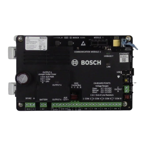
Page 70: Control Panel Board Overview
On-board Ethernet connection, page 32 9 ᅳ USB connector Programming 10 ᅳ Heartbeat LED (blue) 11 ᅳ RESET button 12 ᅳ Terminals for Output B and Output C Open collector outputs, page 50 2017.04 | 15 | F.01U.287.180 Installation Manual Bosch Security Systems, Inc. - Page 71 Configure OUTPUT A using the jumper, page 20 19 ᅳ Battery terminals Secondary (DC) power, page 22 20 ᅳ 18 VAC power input terminals Primary (AC) power, page 22 Bosch Security Systems, Inc. Installation Manual 2017.04 | 15 | F.01U.287.180...
-
Page 72: System Wiring Diagrams
All terminals are supervised except OUTPUT A, OUTPUT B, and OUTPUT C. For proper supervision, do not loop wire under terminals. Break the wire run to provide supervision of connections. 2017.04 | 15 | F.01U.287.180 Installation Manual Bosch Security Systems, Inc. - Page 73 12 ᅳ External relay 6 ᅳ Audible signaling device 13 ᅳ USB connector 7 ᅳ UL Listed four-wire smoke detectors with EOL 14 ᅳ RJ-45 modular jack for Ethernet (optional) resistor Bosch Security Systems, Inc. Installation Manual 2017.04 | 15 | F.01U.287.180...
-
Page 74: Battery Lead Supervision Wiring
Figure 18.2: Battery lead supervision wiring (B5512 shown) Callout ᅳ Description 1 ᅳ D113 Battery Lead Supervision Module, if required 2 ᅳ Batteries 3 ᅳ To supervision point 4 ᅳ Control panel 2017.04 | 15 | F.01U.287.180 Installation Manual Bosch Security Systems, Inc. -
Page 75: 2-Wire Smoke Wiring (B201)
2 ᅳ Interconnect wiring cable 3 ᅳ B201 4 ᅳ EOL resistor 5 ᅳ 1.8 kΩ EOL resistor (P/N: F01U009011) (included with the module) 6 ᅳ Smoke reset wire Bosch Security Systems, Inc. Installation Manual 2017.04 | 15 | F.01U.287.180... -
Page 76: 2-Wire Smoke Wiring (D125B)
UL Listed fire alarm applications, install a D192G Notification Appliance Circuit module. Refer to the D192G Notification Appliance Circuit Module Installation Guide (P/N: 4998122260) for detailed wiring information and specifications. 2017.04 | 15 | F.01U.287.180 Installation Manual Bosch Security Systems, Inc. - Page 77 2 ᅳ Output jumper set to configure OUTPUT A terminal C for AUX POWER (jumper cover removed) 3 ᅳ D192G Notification Appliance Circuit module 4 ᅳ 1k Ω EOL resistor (P/N: F01U033966) Bosch Security Systems, Inc. Installation Manual 2017.04 | 15 | F.01U.287.180...
-
Page 78: Sdi2 Devices General System Wiring
SDI2 bus wiring recommendations Use the following SDI2 bus wiring recommendations for SDI2 installation. The control panel and SDI2 modules use the SDI2 bus to communicate with one another. 2017.04 | 15 | F.01U.287.180 Installation Manual Bosch Security Systems, Inc. - Page 79 Callout ᅳ Description 1 ᅳ Control panel 2 ᅳ SDI2 device (module or keypad) 3 ᅳ Daisy chain wiring 4 ᅳ Single-level T-tapped wiring 5 ᅳ Home run wiring Bosch Security Systems, Inc. Installation Manual 2017.04 | 15 | F.01U.287.180...
- Page 80 Table 18.11: Maximum cable length Notice! Use unshielded cable only. Maximum capacitance of 140nF (140,000 pF) per system. Contact the wire manufacturer for the capacitance ratings of the wire being used. 2017.04 | 15 | F.01U.287.180 Installation Manual Bosch Security Systems, Inc.
-
Page 81: Wiring Label
Avertissement : guide de l'utilisateur (réf. : F01U287181) : seul l'occupant est autorisé à le retirer. Minimum system requirements for Classification in accordance with ANSI/SIA CP-01-2010 Bosch Security Systems, Inc. recommends testing the entire system UL Listed and Classified control unit Model B5512, B4512 or B3512;... -
Page 82: Approved Applications
Control Panels Approved applications The UL System Chart references the components that are evaluated and listed by UL for compatibility with B6512/B5512/B4512/B3512. These components meet the basic system requirements for the applicable standard. Refer to Compatible UL listed components, page 87. - Page 83 15 ᅳ End-of-line (EOL) resistor 8 ᅳ Alarm input point 16 ᅳ Safe Use Terminals 1 through 8. (Select only one.) Use a D113 Battery Lead Supervision Module to supervise the battery connections Bosch Security Systems, Inc. Installation Manual 2017.04 | 15 | F.01U.287.180...
- Page 84 14 ᅳ Terminal TB1 Use Terminals 1 through 8. (Select only one.) Notice! Bell Test at Arming: UL Standard 365 requires a Bell Test at arming for bank safe and vault applications. 2017.04 | 15 | F.01U.287.180 Installation Manual Bosch Security Systems, Inc.
-
Page 85: Fire Applications
When using four-wire smoke detectors, install a power supervision device according to the manufacturer’s instructions. You can connect any number of four-wire smoke detectors to the control panel (subject to available auxiliary power). Bosch Security Systems, Inc. Installation Manual 2017.04 | 15 | F.01U.287.180... -
Page 86: Enclosures
Test Weekly: Perform a Fire Test weekly. According to UL 864, a Fire Test tests both the AC power and the battery. 19.1.4 Enclosures Mount the control panel assembly in any of the Bosch Security Systems, Inc. enclosures listed: – B10 Medium Control Panel Enclosure –... -
Page 87: Combination Fire And Intrusion Alarm Systems
Opt. Opt. Opt. Opt. Communication Module B430 Plug-in Telephone Opt. Opt. Opt. Opt. Opt. Opt. Opt. Communicator B440 Conettix Plug-in Opt. Opt. Opt. Opt. Opt. Opt. Opt. Cellular Communicator Bosch Security Systems, Inc. Installation Manual 2017.04 | 15 | F.01U.287.180... - Page 88 Opt. Opt. Opt. Opt. D192G Class “B”, Style Y Opt. Req. Opt. Opt. Opt. Opt. Opt. Bell Circuit Supervision D8004 Transformer Opt. Opt. Opt. Opt. Opt. Opt. Opt. Enclosure 2017.04 | 15 | F.01U.287.180 Installation Manual Bosch Security Systems, Inc.
-
Page 89: Standby Battery Requirements And Calculations
= ______ B810 ______ x Qty = ______ x Qty = ______ x Qty = ______ B820 ______ x Qty = ______ x Qty = ______ x Qty = ______ Bosch Security Systems, Inc. Installation Manual 2017.04 | 15 | F.01U.287.180... - Page 90 Total Ah requirements must not exceed the Ah capacity of batteries: – One D126 Battery = 7 Ah – Two D126 Batteries = 14 Ah – One D1218 Battery = 18 Ah Table 19.13: General ampere-hour (Ah) calculation formula 2017.04 | 15 | F.01U.287.180 Installation Manual Bosch Security Systems, Inc.
-
Page 91: Household Fire Warning Equipment
One D126 Battery = 7 Ah – Two D126 Batteries = 14 Ah – One D1218 Battery = 17.2 or 18 Ah Table 19.16: Household fire ampere-hour (Ah) calculation formula Bosch Security Systems, Inc. Installation Manual 2017.04 | 15 | F.01U.287.180... -
Page 92: Ul 365 - Police Station Connected Burglar Alarm Units And Systems
Applicable for both IP and cellular communication. Requirement Parameter Supervision interval for IP and Cellular Panel Wide Parameters > Enhanced Communications > Receiver communication is 200 seconds (UL) Supervision Time set to 200 seconds 2017.04 | 15 | F.01U.287.180 Installation Manual Bosch Security Systems, Inc. -
Page 93: Ulc
Supervision Time set to Custom, Poll Rate set to 89, ACK Wait Time set to 15, and Retry Count set to 5 19.8 Conduct testing monthly, with the primary de-energized. Bosch Security Systems, Inc. Installation Manual 2017.04 | 15 | F.01U.287.180... -
Page 94: Keypad Installer Menu
Connect it to the control panel. Use the control panel RESET button to enter SERVICE MODE. The rate of flashing of the Heartbeat LED increases while in SERVICE MODE. 2017.04 | 15 | F.01U.287.180 Installation Manual Bosch Security Systems, Inc. - Page 95 Go to [1] Programming Menu > [1] Reporting > [2] Network > [2] Enhanced Comm Parms. Keypad menu trees This section includes menu trees for the Installer menu structure, and the structures of the B93x/B94x and B91x/B92x keypads user menus, for reference. Bosch Security Systems, Inc. Installation Manual 2017.04 | 15 | F.01U.287.180...
- Page 96 Cellular On-board IP Exit Exit IP Camera SDI2 Cellular (1) Cloud SDI2 Cellular (2) Plug-in Module Srvc Byp menu Versions menu Cloud menu Exit Figure 20.2: Keypad installer menu tree 2017.04 | 15 | F.01U.287.180 Installation Manual Bosch Security Systems, Inc.
- Page 97 <Part On Select Area All On menu <All On Delay <All On Instant <All On Select Area *As configured by your security company. ^B94x only. Figure 20.3: B93x/B94x keypads Main menu tree Bosch Security Systems, Inc. Installation Manual 2017.04 | 15 | F.01U.287.180...
- Page 98 To exit a menu and return to the previous level, press . Notice! If editing a value on the B91x/B92x/B93x keypads, press and hold [ESC] to delete all the characters. 2017.04 | 15 | F.01U.287.180 Installation Manual Bosch Security Systems, Inc.
- Page 99 The B915I keypad uses the following icons, instead of words, on hard keys. All instructions in this section refer to the word key without specifying the B915I icon. B915 key BB915I key [PREV] [▲] [ENTER] [NEXT] [▼] [ESC] [CMD] Bosch Security Systems, Inc. Installation Manual 2017.04 | 15 | F.01U.287.180...
-
Page 100: Program Menu (Programming)
/Next to toggle between the Contact ID and Modem4 option, and press Format while viewing the desired format to select it and save the programming. The keypad shows Parameter saved. Escape from the menu. 2017.04 | 15 | F.01U.287.180 Installation Manual Bosch Security Systems, Inc. -
Page 101: Reporting > [2] Network Menu Parameters
Press Save or Enter. The keypad shows Parameter saved. Depending on keypad model: Press Port # and Edit. -or- Press Next and Enter and then Enter. Delete existing characters, if necessary, and then enter the new number. Bosch Security Systems, Inc. Installation Manual 2017.04 | 15 | F.01U.287.180... -
Page 102: Reporting > [3] Routing Menu Parameters
Phone 1). To keep destination 1, escape from the menu. To change to a different destination (2, 3, or 4), press [Edit Destination], and continue to the next step. Press Save or Enter. The keypad shows Parameter saved. Escape from the menu. 2017.04 | 15 | F.01U.287.180 Installation Manual Bosch Security Systems, Inc. -
Page 103: Reporting > [4] Personal Note Menu Parameters
(1 through 16). Notification Phone number or email address Number ______________________________________________________________________ ______________________________________________________________________ ______________________________________________________________________ ______________________________________________________________________ ______________________________________________________________________ ______________________________________________________________________ ______________________________________________________________________ ______________________________________________________________________ ______________________________________________________________________ ______________________________________________________________________ ______________________________________________________________________ ______________________________________________________________________ ______________________________________________________________________ ______________________________________________________________________ ______________________________________________________________________ Bosch Security Systems, Inc. Installation Manual 2017.04 | 15 | F.01U.287.180... -
Page 104: Network > [1] Ethernet > (Choose The Bus Module Or On-Board) > [1] Module
Go to [1] Programming Menu > [2] Network > [1] Ethernet > (choose the bus module or on-board) > [1] Module Parameters > [2] UPnP Enable. The keypad shows the UPnP current configuration. 2017.04 | 15 | F.01U.287.180 Installation Manual Bosch Security Systems, Inc. -
Page 105: Network > [1] Ethernet > (Choose The Bus Module Or On-Board) > [2] Address
Press Edit or Enter to edit the port number. Delete the existing number, if necessary, and then enter the new number. Press Save or Enter. The keypad shows Parameter saved. Escape from the menu. Bosch Security Systems, Inc. Installation Manual 2017.04 | 15 | F.01U.287.180... -
Page 106: Network > [1] Ethernet > (Choose The Bus Module Or On-Board) > [3] Dns
B450 module. Module 1 settings Module 2 settings Access Point Name _______________________________ _______________________________ Access Pt Username _______________________________ _______________________________ Access Pt Passcode _______________________________ _______________________________ SIM PIN _______________________________ _______________________________ 2017.04 | 15 | F.01U.287.180 Installation Manual Bosch Security Systems, Inc. -
Page 107: Rps > [1] Rps Passcode Menu Parameters
Press Edit or Enter to edit the RPS passcode. Delete the existing number, if necessary, and enter the new number. Press Save or Enter. The keypad shows Parameter saved. Escape from the menu. Bosch Security Systems, Inc. Installation Manual 2017.04 | 15 | F.01U.287.180... -
Page 108: Rps > [2] Rps Phone Number Menu Parameters
This parameter enables or disables specified areas. Enabled areas must have assigned account numbers. In this menu, you can turn on or off areas and assign area account numbers. 2017.04 | 15 | F.01U.287.180 Installation Manual Bosch Security Systems, Inc. - Page 109 Press Enter to edit the account name for the selected area. Delete existing characters, if necessary, and then enter the new characters. Press Save or Enter. The keypad shows Parameter saved. Escape from the menu. Bosch Security Systems, Inc. Installation Manual 2017.04 | 15 | F.01U.287.180...
-
Page 110: Keypad Menu Parameters
Press Edit or Enter to edit the type. Depending on keypad model: Press the icon or softkey for the desired scope. -or- Use Previous or Next to go to the desired scope. 2017.04 | 15 | F.01U.287.180 Installation Manual Bosch Security Systems, Inc. -
Page 111: Users Menu Parameters
USER __ __ __ __ __ __ __ __ __ __ __ ____ USER __ __ __ __ __ __ __ __ __ __ __ ____ USER __ __ Bosch Security Systems, Inc. Installation Manual 2017.04 | 15 | F.01U.287.180... -
Page 112: Points Menu Parameters
Point Index 1 24-hr Instant on Open/Short Point Index 2 24-hr Invisible/Sil on Short Point Index 3 Pull Station Point Index 4 Smoke Detector Point Index 5 Smoke Detector w/Verification 2017.04 | 15 | F.01U.287.180 Installation Manual Bosch Security Systems, Inc. - Page 113 Local While Disarmed Local While Armed Disable Restorals Force Arm Returnable Bypass Returnable Bypassable Swinger Bypass Report Bypass at Occurrence Defer Bypass Report Cross Point Alarm Verify Resettable Alarm Abort Bosch Security Systems, Inc. Installation Manual 2017.04 | 15 | F.01U.287.180...
- Page 114 Audible After Two Fails Invisible Point Buzz on Fault __(1)__ __(0)__ __(0)__ __(0)__ __(0)__ __(0)__ __(0)__ __(0)__ Watch Point Output Response Type __(1)__ __(0)__ __(0)__ __(0)__ __(0)__ __(0)__ __(0)__ __(0)__ 2017.04 | 15 | F.01U.287.180 Installation Manual Bosch Security Systems, Inc.
- Page 115 Supervisi Supervisi Watch Off Point Index Text (blank) (blank) (blank) (blank) (2nd language) Point Type / Response / Gas Point Gas Point Aux AC Part On Circuit Style Supervisi Bosch Security Systems, Inc. Installation Manual 2017.04 | 15 | F.01U.287.180...
- Page 116 ____ Time** (None) Custom Function Disabled Disabled Disabled Disabled Monitor Delay 00:00 00:00 00:00 00:00 Delay Response Disarmed 00:00 00:00 00:00 00:00 Delay Response Armed 00:00 00:00 00:00 00:00 2017.04 | 15 | F.01U.287.180 Installation Manual Bosch Security Systems, Inc.
- Page 117 ____ _____ ____ _____ ____ _____ ____ _____ ____ _____ ____ _____ ____ _____ ____ _____ ____ _____ ____ _____ ____ _____ ____ _____ ____ _____ ____ _____ ____ Bosch Security Systems, Inc. Installation Manual 2017.04 | 15 | F.01U.287.180...
-
Page 118: Disable Programming Menu
Enter the installer passcode, and then open the [1] Installer Menu. Go to [1] Programming Menu > [8] Disable. The keypad shows that programming is enabled. Depending on keypad model: Press Edit and then press No. -or- 2017.04 | 15 | F.01U.287.180 Installation Manual Bosch Security Systems, Inc. -
Page 119: Wireless Menu
Enter the installer passcode, and then open the [1] Installer Menu. Go to [2] Wireless > [1] RF Point Menu > [3] Remove Point RFID. The keypad lists any enrolled points. Bosch Security Systems, Inc. Installation Manual 2017.04 | 15 | F.01U.287.180... -
Page 120: Rf Repeater Menu > [1] Add Repeater
Escape from the menu. 20.2.7 [3] RF Diagnostic Menu > [1] RF Points You can obtain certain wireless point diagnostic information using a keypad and this menu. Point State 2017.04 | 15 | F.01U.287.180 Installation Manual Bosch Security Systems, Inc. -
Page 121: Rf Diagnostic Menu > [2] Rf Repeater Menu
The Wireless diagnostics are presented in two different menus for your convenience. Refer to [3] RF Diagnostic Menu > [1] RF Points, page 120 and [3] RF Diagnostic Menu > [2] RF Repeater Menu, page 121. Bosch Security Systems, Inc. Installation Manual 2017.04 | 15 | F.01U.287.180... -
Page 122: Network Menu
Go to [3] Diagnostics Menu > [4] IP Camera. The keypad shows one of the following statuses: – Not Configured – Not Responding – Bad Password – Online – Missing 2017.04 | 15 | F.01U.287.180 Installation Manual Bosch Security Systems, Inc. -
Page 123: Cloud
Press the icon or softkey for the item for which you want view the version. -or- /Previous or /Next to scroll through the list of items for which you can view the version. Press Enter to view the version. Escape from the menu. Bosch Security Systems, Inc. Installation Manual 2017.04 | 15 | F.01U.287.180... -
Page 124: Cloud Menu
Press Edit or Enter (or escape from the menu to exit without making a change). /Next to go to the desired option. Press Save or Enter. The keypad shows Parameter saved and closes the menu. 2017.04 | 15 | F.01U.287.180 Installation Manual Bosch Security Systems, Inc. -
Page 125: Specifications
13.4 V - Battery Restoral Report sent. Battery float charged. Environmental Temperature 0℃ to +49℃ (+32℉ to 122℉) Relative Humidity 5% to 93% at +32℃ (+90℉) non-condensing Arming stations B942/B942W, B930, B921C, B920, B915/B915I, Keyswitch Bosch Security Systems, Inc. Installation Manual 2017.04 | 15 | F.01U.287.180... - Page 126 Short circuit current - 5 mA Compatible B10 Medium Control Panel Enclosure, B11 Small Control Panel Enclosure, D2203 enclosures Enclosure, D8103 Universal Enclosure, D8108A Attack Resistant Enclosure, D8109 Fire Enclosure 2017.04 | 15 | F.01U.287.180 Installation Manual Bosch Security Systems, Inc.
-
Page 127: Wire Requirements
18 AWG min (up to 12 AWG max) Earth ground 16 AWG min (up to 14 AWG max) BAT + Battery + Bosch supplied wire lead, included with control panel.. BAT - Battery - OUTPUT A NO Output A normally open... -
Page 128: Appendix
The B5512 supports up to 4 modules. The B4512 supports up to 2 modules. The B3512 does not support the B208 module. B208 address number B6512 point numbers B5512 point numbers B4512 point numbers 11 - 18 11 - 18... -
Page 129: B901 Address Settings
Control Panels Appendix | en 129 22.1.3 B901 address settings The B6512 supports four B901 Access Control Modules. Address Designation Disabled 0,1 to 0,4 Doors 1 through 4 22.1.4 B91x address settings Address Switches Bosch Security Systems, Inc. Installation Manual... -
Page 130: Reporting And Device Number Information
1 459 aa uuu All Points Tested by User RsssF NRilTC Local Only Local Only All SDI devices are missing, TsssD NpiET Expansion Module Failure 1 333 00 000 power is shorted 2017.04 | 15 | F.01U.287.180 Installation Manual Bosch Security Systems, Inc. - Page 131 System Peripheral Trouble 3 330 00 zzz Restoral Restore Change another’s password NsDO4 NidiiiiiJViiiii Local Only Local Only or card Change own password NsDO4 NidiiiiiJViiiii Local Only Local Only Bosch Security Systems, Inc. Installation Manual 2017.04 | 15 | F.01U.287.180...
- Page 132 Delete User by User NsD05 NidiiiiJXiiii Local Only Local Only DNS Failure TsB01 NpiddddYS Communication Trouble 1 350 00 DNS Failure Restore NsB01 NpiddddYK Communication Trouble 3 350 00 Restore 2017.04 | 15 | F.01U.287.180 Installation Manual Bosch Security Systems, Inc.
- Page 133 Csiiii Nriaa/idiiiiCF O/C by User 3 401 aa uuu Forced Point Tspppp NriaaXWpppp Zone/Sensor Bypass 1 570 aa ppp Gas Alarm Apppp NriaaGApppp Gas Detected 1 151 aa ppp Bosch Security Systems, Inc. Installation Manual 2017.04 | 15 | F.01U.287.180...
- Page 134 Apppp Nriaa/Mapppp Personal Emergency 1 101 aa ppp Missing Alarm Mpppp NriaaUZpppp General Alarm 1 140 aa ppp Missing Fire Supervision GMpppp NriaaFZpppp Fire Trouble 1 373 aa ppp 2017.04 | 15 | F.01U.287.180 Installation Manual Bosch Security Systems, Inc.
- Page 135 System Reset 1 305 00 000 Relay Reset by Sked NsD20 NaikkkROrrrr Sounder/Relay Reset 3 320 00 000 Relay Reset by User NsD18 NidiiiiROrrrr Sounder/Relay Reset 3 320 00 000 Bosch Security Systems, Inc. Installation Manual 2017.04 | 15 | F.01U.287.180...
- Page 136 Exp. Module Low Batt. 1 338 00 SDI Device Low Battery RsssDt NpiddddEVbb Exp. Module Batt. Restore 3 338 00 Restore SDI Device Missing TsssDt NpiddddEM Exp. Module Failure 1 333 00 2017.04 | 15 | F.01U.287.180 Installation Manual Bosch Security Systems, Inc.
- Page 137 Sked Changed by User NsD06 Nidiiii/aikkkJS Schedule Change 1 630 00 000 Sked has Executed NsD25 NaikkkJR Local Only Local Only Status: Burg Alarm SApppp OriaaBApppp Status: Burg Supervisory STpppp OriaaBSpppp Bosch Security Systems, Inc. Installation Manual 2017.04 | 15 | F.01U.287.180...
- Page 138 Walk Test Mode Emd 3 607 aa uuu Walk Test Start TsssF Nriaa/idiiiiTS Walk Test Mode 1 607 aa uuu Watchdog Reset NsD09 NpiddddYW System Reset 1 305 00 000 2017.04 | 15 | F.01U.287.180 Installation Manual Bosch Security Systems, Inc.
-
Page 139: Sdi2 Address Information
Plug-in Module SDI2 2 – 25 201 – 224 Octo-Input Modules 1 through 24 SDI2 66 – 77 301 – 312 Octo-Output Modules 1 through 12 SDI2 Premises RF Module Bosch Security Systems, Inc. Installation Manual 2017.04 | 15 | F.01U.287.180... -
Page 140: Communication Trouble Device Numbers (Zzzz)
Keypad alarm virtual point numbers (ppp, pppp) Special point numbers identify the originator of manually created keypad alarm events. All special point numbers are defined in the table below. 2017.04 | 15 | F.01U.287.180 Installation Manual Bosch Security Systems, Inc. -
Page 141: Autoip
Navigate to the saved file and double-click on it to add it to the host computer’s registry. – Restart the host computer. Text for the AutoIP.reg file: Windows Registry Editor Version 5.00 [HKEY_LOCAL_MACHINE\SYSTEM\CurrentControlSet\Services\Tcpip\Parameters] "IPAutoconfigurationEnabled"=dword:00000001 Bosch Security Systems, Inc. Installation Manual 2017.04 | 15 | F.01U.287.180... - Page 143 Bosch Security Systems, Inc. Bosch Sicherheitssysteme GmbH 130 Perinton Parkway Robert-Bosch-Ring 5 Fairport, NY 14450 85630 Grasbrunn Germany www.boschsecurity.com © Bosch Security Systems, Inc., 2017...