Table of Contents
Advertisement
Quick Links
SERVICE MANUAL
Caution
If electricity is connected during disassembly, it must be a no load current. If it is load
current, be sure to attach a heat sink to the power-amp IC. This will be damaged if the
above precautions are not followed, as it does not have a sub heat sink attached to it.
Contents
POWER AMPLIFIER
1-2
1-3
1-5
1-8
1-9
This service manual is printed on 100% recycled paper.
COPYRIGHT
2000 VICTOR COMPANY OF JAPAN, LTD.
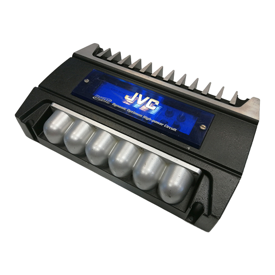
KS-AX6700
J -------- Nothem America
E ----- Continental Europe
No. 49559
Jun. 2000
Advertisement
Chapters
Table of Contents

Related Manuals for JVC KS-AX6700


Summary of Contents for JVC KS-AX6700
-
Page 1: Table Of Contents
KS-AX6700 SERVICE MANUAL POWER AMPLIFIER KS-AX6700 Areas suffix J -------- Nothem America E ----- Continental Europe Caution If electricity is connected during disassembly, it must be a no load current. If it is load current, be sure to attach a heat sink to the power-amp IC. This will be damaged if the above precautions are not followed, as it does not have a sub heat sink attached to it. -
Page 2: Safety Precaution
KS-AX6700 Safety precaution ! CAUTION Burrs formed during molding may be left over on some parts of the chassis. Therefore, pay attention to such burrs in the case of preforming repair of this system. -
Page 3: Location Of Main Parts
KS-AX6700 Location of main parts Volume knob Control panel Heat sink Switch knob Heat sink Rear panel Fuse Output terminal Input for power Low input(R) Heat sink Front panel High input connector Low input(L) - Page 4 KS-AX6700 Heat sink (Bottom view) Main P.C. board GND wire Sub1 P.C. board Main P.C. board 2pin connector Sub2 P.C. board (to CCFL P.C. board) Wire assemb'y (from Main) CCFL P.C. board...
-
Page 5: Removal Of Main Parts
KS-AX6700 Removal of main parts CAUTION: electricity connected during disassembly, it must be a no load current. If it is load current, be sure to attach a heat sink to the power-amp IC. This will be damaged if the above precautions are not followed, as it does not have a sub heat sink attached to it. - Page 6 KS-AX6700 Remove the 6 screws E retaining the panels on both Rear panel sides of the main unit. Fig. 5 Front panel Fig. 6 Remove the 13 screws F attaching the main P.C. board to the bottom of the main unit.
- Page 7 KS-AX6700 Removing the CCFL board (see Fig. 9 to 12) Remove the bottom cover. CCFL cover Then remove the Main P.C. board. From the bottom side of the main unit, remove the 4 screws G retaining the CCFL cover. Fig. 9 Then remove the insulation sheet on top of the CCFL CCFL P.C.
-
Page 8: Adjustment Method
KS-AX6700 Adjustment method Check the voltage and frequency of the secondary FREQUENCY COUNTER toroidal coil. POWER SUPPLY FREQUENCY:24.35kHz ±10Hz VOLTAGE VALUE:55Vp-p 14.4V TEST SET MAIN PCB Measuring Points 2. Measure the secondary toroidal coil, if the standard frequency value of 24.35 kHz ± 10 Hz is not attained, measure the R760 terminal, then adjust the VR701 so that the R760 terminal becomes 24.25 kHz ±... -
Page 9: Wire Connection Diagram
KS-AX6700 Wire connection diagram MAIN PCB WHITE WHITE/BLACK GRAY GRAY/BLACK HIGH INPUT connector CCFL +12V BLACK CCFL PCB... -
Page 10: Ks-Ax6700
KS-AX6700 VICTOR COMPANY OF JAPAN, LIMITED MOBILE ELECTRONICS DIVISION PERSONAL & MOBILE NETWORK B.U. 10-1,1Chome,Ohwatari-machi,Maebashi-city,Japan Printed in Japan (No. 49559) 200006(S) -
Page 11: Block Diagram
KS-AX6700 Block diagram BOOST 0-12dB CROSSOVER INPUT 50-250Hz 12dB/OCT VARIABLE VARIABLE/INV.CIRCUIT(Gain1)/Amplifier POWER R-IN SW101A R-OUT U101 U102 U106 U103 U104 U105 VR101B VR103A VR102A VR102C Q142-Q146 Q148,Q149 Q152 L-OUT Q161-Q166 L-IN SW101B U101 U102 U206 U103 U104 U105 VR101A VR103B... - Page 12 KS-AX6700 Standard schematic diagrams Main board and sub [1/2] /sub2 board circuit diagram SUB2 PCB SUB1 PCB Indicates main signal Caution If electricity is connected during disassembly, it must be a no load current. If it is load current, be sure to attach a heat sink to the power-amp IC. This will be damaged if the...
- Page 13 KS-AX6700 Main board [2/2] and CCFL board circuit diagram CCFL - Inverter board CCFL PCB Parts are safety assurance parts. When replacing those parts make sure to use the specified one. Caution If electricity is connected during disassembly, it must be a no load current. If it is load current, be sure to attach a heat sink to the power-amp IC.
-
Page 14: Printed Circuit Boards
KS-AX6700 Printed circuit boards Main board Surface side view Caution If electricity is connected during disassembly, it must be a no load current. If it is load current, be sure to attach a heat sink to the power-amp IC. This will be damaged if the... - Page 15 KS-AX6700 Bottom side view Caution If electricity is connected during disassembly, it must be a no load current. If it is load current, be sure to attach a heat sink to the power-amp IC. This will be damaged if the...
- Page 16 KS-AX6700 Sub1/sub2 P.C. board (Volume board) CCFL P.C. board...
-
Page 17: Areas Suffix
KS-AX6700 PARTS LIST KS-AX6700 * All printed circuit boards and its assemblies are not available as service parts. Areas suffix --------------- Nothem America E ------------ Continental Europe - Contents - Exploded view of enclosure assembly and parts list Electrical parts list... -
Page 18: Exploded View Of Enclosure Assembly And Parts List
KS-AX6700 Exploded view of enclosure assembly and parts list Block No. - Page 19 KS-AX6700 Parts list ( Enclosure assembly ) Block No. M1MM Item Parts number Parts name Q'ty Description Area MAHS070047-2 HEAT SINK MAFP076019-1 FRONT PANEL MARP706021-1 REAR PANEL MABC076014-1 BOTTOM COVER MATC041489-1 CONTROL PANEL MASO051491-1 CCFL COVER MABR031494-0 TR BRACKET (A)
-
Page 20: Electrical Parts List
KS-AX6700 Eiectrical parts list Electrical parts list ( MAIN PCB ) Block No. 01 Item Remarks Parts number Parts name Area Item Parts number Parts name Remarks Area C 101 ELE4.7/50VSMS CAPACITOR ELECTROLYTIC SM C 728 ELE10/100VSMS CAPACITOR ELECTROLYTIC SM C 102 ELE4.7/50VSMS... - Page 21 KS-AX6700 Electrical parts list ( MAIN PCB ) Block No. 01 Item Remarks Item Parts number Parts name Remarks Area Parts number Parts name Area FH 01 WF-9604 FUSE HOLDER PCB TYPE Q 850 KTA1023Y CARBON RESISTOR SMALL SIGNAL PN...
- Page 22 KS-AX6700 Electrical parts list ( MAIN PCB ) Block No. 01 Item Parts number Parts name Remarks Area Item Parts number Parts name Remarks Area R 247 CAR1/5WJ1K RESISTOR CARBON FILM 1/5 R 757 CAR1/5WJ100 RESISTOR CARBON FILM 1/5 R 248...
- Page 23 KS-AX6700 Block No. 02 Electrical parts list ( SUB1/SUB2/CCFL PCB ) Item Parts number Parts name Remarks Area Item Parts number Parts name Remarks Area C 107 CER470PF50V CAPACITOR CERAMIC DISK 50 R 216 CAR1/5WJ15K RESISTOR CARBON FILM 1/5 C 108...
-
Page 24: Packing And Accessories
KS-AX6700 Packing and accessories Packing and accessories Block No. Block No. Block No. Block No. A1,A2,A7... - Page 25 Area LVT0504-001A INSTRUCTIONS BT-51018-2 WARRANTY CARD BT-51020-2 J=REGIST CARD BT-52004-1 WARRANTY CARD BT-54013-1 WARRANTY CARD CHD114-N CONNECTOR ASS'Y ACCES FUSE25A/32V AUTO FUSE MOCU014167-0 RUBBER RING MBSC02240-20 SCREW BT-20071B JVC CENTER LIST KIT 1 KSAX6300-SCREW SCREW PARTS KIT A5, A6, P6...