Table of Contents
Advertisement
SERVICE MANUAL
PRODUCT CODE
1 122 268 00 PLV-Z3 (S)
1 122 269 00 PLV-Z3 (S)
1 122 269 02 PLV-Z3 (S)
1 122 268 20 PLV-Z3 (K)
1 122 269 20 PLV-Z3 (K)
1 122 269 22 PLV-Z3 (K)
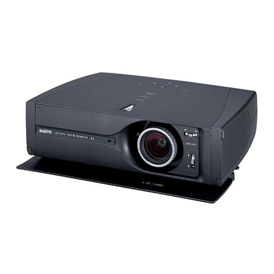
Multimedia Projector
(M4SA)
(P4SA)
(P4SC)
(M4SAA)
(P4SAA)
(P4SCA)
FILE NO.
Model No. PLV-Z3
(U.S.A., Canada, Europe
Asia, Africa, U.K. )
Original Version
Chassis No. M4S-Z300
M4S-Z3S00
NOTE: Match the Chassis No. on the unit's
back cover with the Chassis No. in
the Service Manual.
If the Original Version Service
Manual Chassis No. does not
match the unit's, additional Service
Literature is required. You must refer
to "Notices" to the Original Service
Manual prior to servicing the unit.
REFERENCE NO.
SM5110679-00
Advertisement
Table of Contents

Related Manuals for Sanyo PLV-Z3


Summary of Contents for Sanyo PLV-Z3
- Page 1 Manual Chassis No. does not match the unit’s, additional Service Literature is required. You must refer PRODUCT CODE to “Notices” to the Original Service 1 122 268 00 PLV-Z3 (S) (M4SA) Manual prior to servicing the unit. 1 122 269 00 PLV-Z3 (S) (P4SA)
-
Page 2: Table Of Contents
■ Contents ■ Safety Instructions ......................3 ■ Specifications ........................4 ■ Circuit Protections ......................5 ■ Lamp Replacement ......................7 ■ Cleaning ..........................8 ■ Mechanical Disassemblies ....................10 ■ Optical Parts Disassemblies..................15 ■ LCD Panel/Prism Ass'y Replacement ................19 ■ Adjustments After Parts Replacement ................20 ■... -
Page 3: Safety Instructions
■ Safety Instructions SAFETY PRECAUTIONS WARNING: The chassis of this projector is isolated (COLD) from AC line by using the converter transformer. Primary side of the converter and lamp power supply unit circuit is connected to the AC line and it is hot, which hot circuit is identified with the line ( ) in the schematic diagram. -
Page 4: Specifications
■ Specifications Technical Specifications Projector Type Multimedia Projector Dimensions 14.13" x 4.59" x 10.77" (359mm x 116.7mm x 273.5mm) (not including raised portions) (W x H x D) Net Weight 9.0 lbs (4.1 kg) LCD Panel System 0.7” wide TFT Active Matrix type, 3 panels Panel Resolution 1280 x 720 dots Number of Pixels... -
Page 5: Circuit Protections
■ Circuit Protections This projector is equipped with the following protections to operate in safety. If the abnormality occurs inside the projector, it will turn off the projector by operating one of the following protections. ● Fuse The fuse is located on the ass'y-Inlet. When either the LAMP indicator or the READY indicator is not illuminated, Ass’y Inlet fuse may be opened. -
Page 6: Warning Temperature And Power Failure Protection
Circuit Protections ● Front cover switch (Door switch) When the front cover is closed, the ready indicator lights orange and the projector cannot be turned on. While operating the projector, if the front cover is closed, Door SW (inside the cabinet) turn off the projector. -
Page 7: Lamp Replacement
ORDER REPLACEMENT LAMP Replacement lamp can be ordered through your dealer. When ordering a projection lamp, give the following information to the dealer. ● Model No. of your projector PLV-Z3 ● Replacement Lamp Type No. POA-LMP86 (Service Parts No. 610 317 5355) ■... -
Page 8: Cleaning
■ Cleaning After long periods of use, dust and other particles will accumulate on the LCD panel, prism, mirror, polarized glass, lens, etc., causing the picture to darken or color to blur. If this occurs, clean the inside of optical unit. Remove dust and other particles using air spray. -
Page 9: Cleaning The Air Filter
Cleaning Cleaning the Air Filter The air filters prevent dust from accumulating on the surface of the optical elements inside the projector. Should the air filters become clogged with dust particles, it will reduce cooling fans’ effectiveness and may result in internal heat build up and adversely affect the life of the projector. -
Page 10: Mechanical Disassemblies
■ Mechanical Disassemblies [Attention] This LCD projector is used the different kind of screw. The using correct screw is needed to prevent the damage. CABINET - TOP REMOVAL 1. Remove 6 screws to take the Cabinet Top upward off. Cabinet Top Fig. - Page 11 Mechanical Disassemblies 4. DOOR ASS'Y REMOVAL Door Ass'y 1. Remove 6 screws to take the Door Ass'y off. Note: Can be removed Door itself. See below. Fig. 4 5. DOOR LEG AND DOOR SWITCH BOARD REMOVAL 1. Remove a screw to take each leg off. Door Switch Board 2.
- Page 12 Mechanical Disassemblies 7. LAMP BALLAST UNIT REMOVAL Filter Holder 1. Remove 4 screws to take the Filter Holder off. 2. Remove 3 screws to take the Filter Board off. 3. Remove 3 screws to take the Inlet Board off. Filter Board Inlet Board Fig.
- Page 13 Mechanical Disassemblies 9. POWER BOARD REMOVAL 1. Remove 2 screws to take the Lamp SW Board off. 2. Remove a screw and 4 screws to open the Power Board Cover and take the R/C Board off. 3. Remove 4 screws to take the Power Board off.
- Page 14 Mechanical Disassemblies 11. FANS REMOVAL 1. Remove 2 screws and 5 screws to take the Fan Cover off. 2. Remove a screw to take the Sensor Board off from Fan Cover the Fan Cover. 3. Remove 2 screws to take the Duct Cover-A off. Sensor Board 4.
-
Page 15: Optical Parts Disassemblies
■ Optical Parts Disassemblies Before taking this procedure, remove Cabinet Top and Main board following to the “Mechanical Disassemblies”. Disassembly requires a 2.0mm hex wrench and a screwdriver. PROJECTION LENS REMOVAL 1. Remove 2 screws to slide the Lens Spacer off. Projection Lens 2. - Page 16 Optical Parts Disassemblies RELAY LENS REMOVAL Relay Lens 1. Remove 2 screws and pull the Relay Lens Ass’y upward. 2. Remove 2 screws to take the Lens off from the Relay Lens Ass’y Holder. Fig. 3 POLARIZED GLASS-IN REMOVAL Blue 1.
- Page 17 Optical Parts Disassemblies POLARIZED GLASS-OUT AND WIDE VIEW PLATE REMOVAL Stopper 1. Remove 4 screws and take the LCD Panel/Prism Ass’y upward from the Optical Unit. LCD Panel/Prism Ass’y 2. Remove the stopper and take the glass off upward. Polarized Glass-Out Film Note 1...
- Page 18 Optical Parts Disassemblies LOCATIONS IN OPTICAL UNIT When mounting or assembling the optical parts in the optical unit, the parts must be mounted specified location as shown in figure below. Cut Face Cut Face Marking Marking Key No. Description Lens (Condenser G) Lens (Condenser R) Prism Beam Splitter (PBS) Condenser Lens (Out)
-
Page 19: Lcd Panel/Prism Ass'y Replacement
■ LCD Panel/Prism Ass'y Replacement LCD PANEL/PRISM ASS'Y REMOVAL 1. Remove Cabinet Top and Main Board. 2. Remove 4 screws by a 2.0mm hex wrench to take the Panel/Prism Ass'y off from the Optical Unit. Note: Do not replace the LCD panel separately other- wise it can not obtain proper picture. -
Page 20: Adjustments After Parts Replacement
■ Adjustments After Parts Replacement ● ❍ : Adjustment necessary : Check necessary Disassembly / Replaced Parts LCD/ Polarized glass Power Main Condenser Relay Prism Lens Lens Board Board Ass’y Contrast Adjustment ❍ ● R-Contrast adjustment ❍ ● G-Contrast adjustment ❍... -
Page 21: Optical Adjustment
■ Optical Adjustment Before taking optical adjustments below, remove the Cabinet Top and Main Board following to the “Mechanical Disassemblies” Adjustments require a 2.0mm hex wrench and a slot screwdriver. When you adjust Integrator lens or Relay lens adjustment, you need to disconnect some connectors and FPC cables of LCD panels on the main board. Note: Do not disconnect connectors on the main board, because the projector can not turn on or operate properly for adjustment. - Page 22 Optical Adjustment INTEGRATOR LENS ADJUSTMENT 1. Turn the projector on by a state of without FPC cables. 2. Project all of lights on the screen. 3. Adjust the adjustment base of integrator lens ass’y to make color uniformity in white. Note: When adjust right or left, loosen 1 screw A.
-
Page 23: Electrical Adjustment
Normal Mode "S" mark display Service mode INPUT DOWN Service Mode LIGHT RESET CANCEL MENU POWER ON-OFF SELECT SCREEN Service Mode SANYO IMAGE ADJ. INPUT Video Image Powerful Group Data 1.00 JAPAN TempA TempB TempC 23.45 46.78 34.56 Fan1 Speed Fan2 Speed Fan3 Speed Fan4 Speed... -
Page 24: Circuit Adjustments
Electrical Adjustments ● Circuit Adjustments CAUTION: The each circuit has been made by the fine adjustment at factory. Do not attempt to adjust the follow- ing adjustments except requiring the readjustments in servicing otherwise it may cause loss of perfor- mance and product safety. - Page 25 Electrical Adjustments Reference adjustment PC Pedestal adjustment Equipment Oscilloscope Equipment Oscilloscope Input mode Computer [RGB(Analog)] Input mode Computer [RGB(Analog)] Image mode Powerful Image mode Powerful Input signal 16-step gray scale computer signal Input signal 16-step gray scale signal (720p) (720p format) 1.
- Page 26 Electrical Adjustments Common Center adjustment White Balance adjustment Input mode Computer [RGB(Analog)] Input signal 16-step gray scale signal Image mode Powerful Input signal 1 line dot pattern 720p computer signal 9-a Input mode Computer [RGB(Analog)] Image mode Powerful 1. Enter the service mode. Input format 720p computer signal 2.
-
Page 27: Service Adjustment Data Table
Electrical Adjustments ● Service Adjustment Data Table These initial values are the reference data written from the CPU ROM to memory IC when replaced new memory IC. The adjust- ment items indicated with “✻” are required to readjust following to the “Electrical adjustments”. Other items should be used with the initial data value. -
Page 28: Electrical Adjustments
Electrical Adjustments Adjustment Item Initial Value Range Input source / Description SHP F1 0/0/1/1/1/1/1/0 0 ~ 3 SYSTEM 0/0/1/1/2/2/2/0 0 ~ 3 PRE/OVER 1/1/1/1/1/1/1/1 0 ~ 3 LTI PH 31/31/31/31/31/31/31/0 0 ~ 63 R-Y/R 10/13/10/13/6/6/6/0 0 ~ 15 R-Y/B 6/8/6/8/7/7/7/0 0 ~ 15 G-Y/R 9/8/9/8/8/8/8/0... - Page 29 Electrical Adjustments Adjustment Item Initial Value Range Input source / Description LINE_R3 1016 0 ~ 1023 LINE_R4 1008 0 ~ 1023 LINE_G0 0 ~ 1023 LINE_G1 0 ~ 1023 LINE_G2 0 ~ 1023 LINE_G3 1016 0 ~ 1023 LINE_G4 1008 0 ~ 1023 LINE_B0 0 ~ 1023...
- Page 30 Electrical Adjustments Adjustment Item Initial Value Range Input source / Description Group: 8 DAC (M62398) R_VIDEO_CENTER 0 ~ 255 DACR G_VIDEO_CENTER 0 ~ 255 DACG B_VIDEO_CENTER 0 ~ 255 DACB REF_R 0 ~ 255 DACR White-black adjustment REF_G 0 ~ 255 DACG White-black adjustment REF_B 0 ~ 255...
- Page 31 Electrical Adjustments Adjustment Item Initial Value Range Input source / Description DIMMER_CTRL_LEVEL6 60/70/255 0 ~ 255 DIMMER_CTRL_LEVEL7 54/63/255 0 ~ 255 DIMMER_CTRL_LEVEL8 48/56/80 0 ~ 255 DIMMER_CTRL_LEVEL9 42/49/70 0 ~ 255 DIMMER_CTRL_LEVEL10 36/42/60 0 ~ 255 DIMMER_CTRL_LEVEL11 30/35/50 0 ~ 255 DIMMER_CTRL_LEVEL12 24/28/40 0 ~ 255...
- Page 32 Electrical Adjustments Adjustment Item Initial Value Range Input source / Description Auto Watt Min Fan4 Max 65/65/65/75 30 ~ 145 Auto TempA Low 34/34/32/26 10 ~ 100 Auto TempA High 40/42/40/37 10 ~ 100 Auto TempB Low 75/73/73/68 10 ~ 100 Auto TempB High 78/76/76/71 10 ~ 100...
- Page 33 Electrical Adjustments Adjustment Item Initial Value Range Input source / Description Group: 500 NTSC (Composite/S-video) overscan at I/P OFF TOTAL DOTS 1850 DISP DOTS 1516 H BACK PORCTH V BACK PORCTH DISP LINE CLAMP WIDTH Group: 501 NTSC (Composite/S-video) overscan at I/P ON TOTAL DOTS 1850 DISP DOTS...
- Page 34 Electrical Adjustments Adjustment Item Initial Value Range Input source / Description V BACK PORCTH DISP LINE CLAMP WIDTH Group: 511 HDTV 720p-50 overscan (Component) TOTAL DOTS 1980 DISP DOTS 1280 H BACK PORCTH V BACK PORCTH DISP LINE CLAMP WIDTH Group: 512 HDTV 1035i overscan (Component) at I/P OFF TOTAL DOTS 2200...
- Page 35 Electrical Adjustments Adjustment Item Initial Value Range Input source / Description Group: 521 RGB 575p overscan TOTAL DOTS DISP DOTS H BACK PORCTH V BACK PORCTH DISP LINE CLAMP WIDTH Group: 522 RGB 720p overscan TOTAL DOTS 1650 DISP DOTS 1280 H BACK PORCTH V BACK PORCTH...
-
Page 36: Location Of Test Points
Electrical Adjustments ● Location of Test Points MAIN BOARD K66E K66D K801 K35B TPICE TEICE TPDCLK TPDVS TPDHS TPSDATA K35R TE8201 TP_BIN TP_RIN TP_GIN TPGHS TP4101 -36-... -
Page 37: Waveform
■ Waveform VIDEO-IN < IC2101-(7)> Analog V-SYNC <TPGVS> Digital H-SYNC <TPDHS> Digital V-SYNC <TPDVS> PC_16STEP-IN<TP-GIN> PC-16STEP-OUT <TP35G> Component_Y <IC6201-(6)> Component_Cb<IC6201-(5)> Component_Cr <IC6201-(3)> PC_R-IN<TP-RIN> PC_G-IN<TP-GIN> PC_B-IN<TP-BIN> R-S&H OUT<TP35R > G-S&H OUT <TP35G> B-S&H OUT <TP35B> -37-... -
Page 38: Chassis Block Diagram
■ Chassis Block Diagram ● Chassis Overview B-LCD PANEL G-LCD PANEL R-LCD PANEL LAMP_PWM IC1824 I/O_EXP. IC1823 IC5801 O_EXP. MOTOR DRIVER IC5361 SYNC SW IC1822 O_EXP IC4101 PC/AV SW IC1821 O_EXP. IC1801 BUFFER IC6201 YUV-SW HDMI D-SUB_15 SERVICE RESET HDMI COMPUTER COMPONENT-1 COMPONENT-2... -
Page 39: Video Signal Processing Circuit And Lcd Panel Driving Circuit
Chassis Block Diagrams ● Video signal processing circuit and LCD panel driving circuit SCLK/SDATA TP35B TP35G ROUT GOUT BOUT TP35R SYNC_Y GSYNC HDMI D-SUB_15 COMPONENT_1 COMPONENT_2 HDMI COMPUTER S-VIDEO VIDEO Y/Cb/Cr Y/Cb/Cr -39-... -
Page 40: Chassis Block Diagrams
Chassis Block Diagrams ● Visual signal flow INPUT SIGNAL VIDEO Composite Video S-VIDEO S-VIDEO 480i/575i COMPONENT_1/2 480p/575p/720p/1080i RGB (SCART) COMPUTER RGB (Analog) HDMI HDMI ● Sync signal flow INPUT SIGNAL VIDEO Composite Video S-VIDEO S-VIDEO 480i/575i COMPONENT_1/2 480p/575p/720p60/1080i 720p (50Hz) RGB (SCART) COMPUTER RGB (Analog) - Page 41 Chassis Block Diagrams ● RGB digital signal processing circuit GLOSSARY HDMI : High Definition Multimedia Interface HDCP : High bandwidth Digital Content Protection TMDS : Transmission Minimized Differential Signaling HOTPLUG HDMI_HPD IC8102 IC1824 SDA3 (SDA) IC8131 EXPANDER EEPROM SCL3 (SCL) DDC_SDA DDC_SCL IC301...
-
Page 42: System Controls
Chassis Block Diagrams ● System Controls 19-22 25 13-16 7-10 5-6 41-44 47-48 LED-On: H IC1501 IC1822 IC1821 OUTPUT OUTPUT EXPANDER EXPANDER IC1531 IC501, IC531, IC561 S&H IC1823 OUTPUT EXPANDER IC4811 INVERTER IC1824 IC1801 BUS BUFFER EXPANDER IC4841 LAMP CPU IC4826 NAND OPTION... -
Page 43: Power Supply Lines
■ Power Supply Lines ● Power supply circuit, Protection circuit and Fan control circuit FN901 FN902 FN903 FN904 FN905 Fan Lock : H AV BOARD MAIN BOARD UNIT_POWER FAN_ERR D7821 K50A K10J FAN CONTROL Q7821 D7807 5VHDMI MC201 FAN1 FAN_CONT1 TPFAN1 D7808 K50B K10K... -
Page 44: Troubleshooting
■ Troubleshooting ● No Power This projector provides a function which can be specified a defective area simply by indicating the LEDs on the con- trol panel. Connect the AC cord and press the Power button once and then check the LED indication. Indicators Troubleshooting WARNING... - Page 45 Troubleshooting Indicators Troubleshooting WARNING POWER red/green From previous page The symptom indicates that the projector detected an abnormality in the lamp driving signal. Check the lamp driving signal. POWER (red) LAMP_POW signal (Power-on:L) is output from pin 19 of indicator is flash- IC1824 and sent to IC4841 via IC4826.
-
Page 46: No Picture
Troubleshooting ● No Picture Check following steps. Description of visual signal flow Sync: Description of Sync signal flow Check signal processing stage and LCD driving stage; No picture with all of input sources Check RGB S&H signals at test points TP35R, TP35G, TP35B. Check power supply circuit 15V and peripheral circuit. - Page 47 Troubleshooting From previous page No picture with Check Computer source input stage; Computer (RGB analog) Check RGB signals at test points TP-RIN/GIN/BIN. input source Check IC4101, IC8201 and peripheral circuits. Check sync signals at test points TPGHS and TPGVS. PC_RGB signals are selected in IC4101 and sent to IC8201. They are A/D-converted in IC8201 and sent to IC301.
-
Page 48: Control Port Functions
■ Control Port Functions ● I/O Port Table of Main CPU (IC301, PW385) Pin No. Name Function Name Function Polarity Port A7 LAMP_PWM PWM Output to Lamp_CPU Port A6 Not used Port A5 SCL3 Port A4 SDA3 Port A3 SCL1 Port A2 SDA1 Port A1... - Page 49 Control Port Functions ● Lamp Control CPU (IC4841, PIC12F675) Pin No. Name Function Note Polarity Power Supply +5V GP5/T1CKI TMR1_CLK Clock Input Power switch signal Low Wattage = L Lamp Status Signal GP2/T0CKI LAMP_PWM APL Level Input SCEL Lamp ON/OFF Control Lamp ON = L LAMP_ERR Lamp Error Output...
- Page 50 Control Port Functions ● Parallel Bus I/O Expander IC Ref. No Signal Name Function Note IC1821 MCLK_SEL Not used Key Scan Output TC74LCX574 Key Scan Output Key Scan Output READY_LED Ready LED PWR_LED Power LED R/C_1/2 LAMP_LED Lamp Replace LED IC1822 FAN_SW Power ON: High...
-
Page 51: Ic Block Diagrams
■ IC Block Diagrams ● AD9981 <Analog Flat Panel Interface, IC8201> Auto Clamp Auto Clamp Level Adjust Level Adjust Pr/Red Clamp Clamp 1 0-bit ADC 1 0-bit ADC Cb/Cr/Red Pr/Red Auto Clamp Auto Clamp Level Adjust Level Adjust Y/Green Clamp Clamp 1 0-bit ADC 1 0-bit ADC... - Page 52 IC Block Diagrams ● CXA2175 <Video Selector, IC4101> ● L3E06110 <LCD Driver, > IC501, IC531, IC561 CONTROL LOGIC DAC LATCHES -52-...
- Page 53 IC Block Diagrams ● L3E07090 <Color Shading Correction, IC401> ● M51204 <Comparator, IC881> ● NJM2584 <Video Switch, IC6201> Output Reverse Input Input COMPARATOR Control Pin H = B channel output L = A channel output OPEN = A channel output -53-...
- Page 54 IC Block Diagrams ● SiI9993 <HDMI Interface supporting HDCP, IC8001> RESET Registers & SiI 9993 Configuration Logic S/PDIF Audio Decoder EEPROM HDCP HDCP Keys Cipher 10-bit Pb/B EXT_RES Pr/R D [23-0] RGB-to-YCbCr Color Space Mask TMDS VSYNC Converter Receiver 4:2:2 to 4:4:4 HSYNC Up/Down Converter ODCK...
- Page 55 IC Block Diagrams ● TB1274 <Video Decoder, IC3101> ● TC90A69F <3 Line Digital Comb Filter, IC2101> -55-...
-
Page 56: Service Parts List
■ Electrical Parts List M4S-Z300, M4S-Z3S00 Product safety should be considered when a component replacement is made in any area of a projector. Components indicated by a mark in this parts list and the circuit diagram show components whose value have special significance to product safety. - Page 57 M4S-Z300, M4S-Z3S00 Electrical Parts List Note: Parts order must contain Chassis No., Part No., and Descriptions. ● ASSEMBLIED BOARDS Door Switch Board Main Board LED Board R/C Board Filter Board Inlet Board Power Board F601 Fuse Lamp Ballast Unit Sensor Board Lamp SW Board AV Board ●...
- Page 58 M4S-Z300, M4S-Z3S00 Electrical Parts List Key No. Part No. Description Key No. Part No. Description 405 163 1612 TR 2SC2812N-L6-TB0 ASSEMBLIED BOARDS 405 163 1711 TR 2SC2812N-L7-TB0 Q2141 405 014 4519 TR 2SC2412K T146 R 610 308 8013 ASSY,PWB,INLET M4KA 405 014 4618 TR 2SC2412K T146 S 610 308 8020 ASSY,PWB,FILTER M4KA...
- Page 59 M4S-Z300, M4S-Z3S00 Electrical Parts List Key No. Part No. Description Key No. Part No. Description 405 163 1711 TR 2SC2812N-L7-TB0 Q4611 405 002 8324 TR 2SA1203-Y-TE12L Q3142 405 014 4519 TR 2SC2412K T146 R Q4612 405 014 4519 TR 2SC2412K T146 R 405 014 4618 TR 2SC2412K T146 S 405 014 4618...
- Page 60 M4S-Z300, M4S-Z3S00 Electrical Parts List Key No. Part No. Description Key No. Part No. Description 405 002 0318 TR 2SA1037K T146 R Q6252 405 134 5925 TR 2SA1037AK-T146-R 405 002 0417 TR 2SA1037K T146 S 405 147 2215 TR 2SA1037AK-S-T146 405 002 6726 TR 2SA1179-M6-TB 405 002 0318...
- Page 61 M4S-Z300, M4S-Z3S00 Electrical Parts List Key No. Part No. Description Key No. Part No. Description 405 163 1513 TR 2SA1179N-M6-TB IC8801 409 481 8612 IC LM76CHMX-5 405 163 2718 TR 2SA1179N-M7-TB IC881 409 347 5410 IC M51204FP-600C Q8851 406 018 3307 TR 2SD1383K T146 B IC8811 409 481 8612...
- Page 62 M4S-Z300, M4S-Z3S00 Electrical Parts List Key No. Part No. Description Key No. Part No. Description C2132 403 164 0234 CERAMIC 0.1U Z C317 403 164 0234 CERAMIC 0.1U Z C2141 403 164 0234 CERAMIC 0.1U Z C3171 403 157 2911 CERAMIC 47P J C2142...
- Page 63 M4S-Z300, M4S-Z3S00 Electrical Parts List Key No. Part No. Description Key No. Part No. Description C4111 403 378 3117 CERAMIC 47U Z 6.3V C5201 403 348 5823 CERAMIC 0.47U K C4113 403 164 0234 CERAMIC 0.1U Z C5202 403 348 5823 CERAMIC 0.47U K C4114...
- Page 64 M4S-Z300, M4S-Z3S00 Electrical Parts List Key No. Part No. Description Key No. Part No. Description C5614 403 164 0234 CERAMIC 0.1U Z C6392 403 391 5112 ELECT 100U M C5616 403 215 2112 CERAMIC 8200P K C7841 403 391 5112 ELECT 100U M C5617...
- Page 65 M4S-Z300, M4S-Z3S00 Electrical Parts List Key No. Part No. Description Key No. Part No. Description C9403 403 164 0234 CERAMIC 0.1U Z R1844 401 105 5410 MT-GLAZE 47K JA 1/16W C9404 403 164 0234 CERAMIC 0.1U Z R2101 401 105 4611 MT-GLAZE 3.9K JA 1/16W C9406...
- Page 66 M4S-Z300, M4S-Z3S00 Electrical Parts List Key No. Part No. Description Key No. Part No. Description R3163 401 105 0514 MT-GLAZE 1K JA 1/16W R4112 401 105 1412 MT-GLAZE 150 JA 1/16W R3164 401 105 7919 MT-GLAZE 0.000 ZA 1/16W R412 401 105 7919 MT-GLAZE 0.000 ZA 1/16W...
- Page 67 M4S-Z300, M4S-Z3S00 Electrical Parts List Key No. Part No. Description Key No. Part No. Description R481 401 105 0316 MT-GLAZE 10 JA 1/16W R5320 401 105 5410 MT-GLAZE 47K JA 1/16W R4811 401 105 2716 MT-GLAZE 220 JA 1/16W R5321 401 105 2815 MT-GLAZE 2.2K JA 1/16W...
- Page 68 M4S-Z300, M4S-Z3S00 Electrical Parts List Key No. Part No. Description Key No. Part No. Description R5624 401 105 3812 MT-GLAZE 30K JA 1/16W R6252 401 105 0514 MT-GLAZE 1K JA 1/16W R5626 401 105 2112 MT-GLAZE 18K JA 1/16W R6253 401 105 0514 MT-GLAZE 1K JA 1/16W...
- Page 69 M4S-Z300, M4S-Z3S00 Electrical Parts List Key No. Part No. Description Key No. Part No. Description R8143 401 105 5311 MT-GLAZE 4.7K JA 1/16W R8814 401 105 0613 MT-GLAZE 10K JA 1/16W R8144 401 105 5311 MT-GLAZE 4.7K JA 1/16W R882 401 105 2518 MT-GLAZE 20K JA 1/16W...
- Page 70 M4S-Z300, M4S-Z3S00 Electrical Parts List Key No. Part No. Description Key No. Part No. Description 645 021 4943 R-NETWORK 22X4 1/16W RB534 645 037 0656 R-NETWORK 0X4 0.063W RB377 645 037 0663 R-NETWORK 22X4 0.063W 645 024 7477 R-NETWORK 0X4 1/16W 645 021 4943 R-NETWORK 22X4 1/16W RB561...
- Page 71 M4S-Z300, M4S-Z3S00 Electrical Parts List Key No. Part No. Description Key No. Part No. Description D444 407 149 0817 DIODE 1SS355-TE-17 AV BOARD D4601 407 209 4519 ZD UDZS-TE-176.8B D4602 407 218 7716 ZENER DIODE UDZS20B-TE-17 610 315 9232 ASSY,PWB,AV M4SA D4801 407 209 1211 ZD UDZS-TE-176.2B...
- Page 72 M4S-Z300, M4S-Z3S00 Electrical Parts List Key No. Part No. Description Key No. Part No. Description CAPACITOR R1033 401 105 5410 MT-GLAZE 47K JA 1/16W C1002 403 164 0214 CERAMIC 0.1U Z R1034 401 105 0415 MT-GLAZE 100 JA 1/16W C1007 403 164 0214 CERAMIC 0.1U Z...
- Page 73 M4S-Z300, M4S-Z3S00 Electrical Parts List Key No. Part No. Description Key No. Part No. Description R8057 401 105 0415 MT-GLAZE 100 JA 1/16W MISCELLANEOUS R8058 401 105 0415 MT-GLAZE 100 JA 1/16W K10A 645 068 3350 SOCKET,IF(HDMI) 19P R8059 401 105 7919 MT-GLAZE 0.000 ZA 1/16W K10B...
- Page 74 M4S-Z300, M4S-Z3S00 Electrical Parts List Key No. Part No. Description Key No. Part No. Description R2869 401 105 0514 MT-GLAZE 1K JA 1/16W ACCESSORIES DIODE D2851 407 208 9713 ZD UDZS-TE-175.6B D2852 407 208 9713 ZD UDZS-TE-175.6B PRINTED MATTER / OWNER'S MANUAL D2853 407 208 9713 ZD UDZS-TE-175.6B...
-
Page 75: Mechanical Parts List
■ Mechanical Parts List M4S-Z300, M4S-Z3S00 Note: Parts order must contain Chassis No., Part No., and Descriptions. ● CABINET PARTS …S12 -75-... - Page 76 M4S-Z300, M4S-Z3S00 Mechanical Parts List Key No. Part No. Description Key No. Part No. Description PLV-Z3 (K) M4S-Z300 PLV-Z3 (S) M4S-Z3S00 CABINET PARTS CABINET PARTS No.1 610 317 6420 CABINET FRONT SERVICE-M4SA No.1 610 319 8934 CABINET FRONT SERVICE-M4SAA (Including Key No.1-a,1-b) (Including Key No.1-a,1-b)
- Page 77 M4S-Z300, M4S-Z3S00 Mechanical Parts List Key No. Part No. Description Key No. Part No. Description PLV-Z3 (S)(K) M4S-Z3S00/Z300 compatible PLV-Z3 (S)(K) M4S-Z3S00/Z300 compatible OPTICAL PARTS CHASSIS PARTS No.L1 645 069 6244 ASSY,LENS,PROJECTION No.M1 610 318 1592 COMPL,MOUNTING LNS-M4SA No.M2 610 310 1927 COVER DUCT EXIT POW-M4KA No.L2...
-
Page 78: Optical Parts List
■ Optical Parts List M4S-Z300, M4S-Z3S00 Note: Parts order must contain Chassis No., Part No., and Descriptions. L16 (R) L18 (B) L17 (G) L2-a (R) L2-b (G) L2-c (B) -78-... - Page 79 M4S-Z300, M4S-Z3S00 Optical Parts List -79-...
- Page 80 SANYO Electric Co., Ltd. (M4SA) Nov. 2004 BB 400 Printed in Japan...
- Page 81 PLV-Z3(S) M4S-Z3S00 These schematic diagrams and printed wiring board drawings are part of the serv- ice manual original for chassis No. M4S-Z300, M4S-Z3S00 model PLV-Z3. File with the service manual No. SM5110679-00. Note: All the information of part numbers and values indicated on these diagrams are at the beginning of production.
-
Page 82: Parts Description And Reading In Schematic Diagram
■ Parts description and reading in schematic diagram M4S-Z300 1. The parts specification of resistors, capacitors and Resistor Reading coils are expressed in designated code. Please check Example 1/2 D J 10K B the parts description by the following code table. 2. -
Page 83: Schematic Diagrams
■ Schematic Diagrams COLD SIDE HOT SIDE FILTER INLET R8851 1/16GZ0C K28D A2801 K8801_3 C2804 AC CORD J10EG040G C2801 U22B0080G R2804 6.3KZ 10KZ1U K8801_2 J10EZ040G 1/16GJ47C 47ME K28D_1 AC100-120V K8801_1 1 VOUT K601 SW902 AC200-240V J11B5760N VA611 R611 C611 C612 C613 C614 S10B5540N... - Page 84 D1001 UDZS SC1001 6.2BG Z30B0140G HDMI_HPD R1001 DDCSCL 1/16 GZ0C SC1002 DDCSCL Z30B0140G DDC_SDA DDC_SDA DDCSDA D1003 DDCSDA UDZS SDA0 K10A 6.2BG SC1003 J11B6780M Z30B0140G DDC_SCL SCL0 SIGE[0-9] DDC_SCL D1004 SIRST UDZS 6.2BG C1002 D1002 SC1004 5VHDMI K10A_19 C1001 UDZS Z30B 25KZ 0.1GQF...
- Page 85 K50A SCREW101 SCREW102 SCREW103 J10ML540G IC3601 K50A_1 5VHDMI 8 9 10 8 9 10 11 12 13 14 8 9 10 PQ033EZ01ZP K50A_5 SCREW104 SCREW105 SCREW106 HOTPLUG FROM IC301(PW385) DDC_SDA K50A_7 DDC_SDA TO IC8102 K50A_9 DDC_SCL 8 9 10 11 12 13 14 8 9 10 11 12 13 14 8 9 10 11 12 13 14 DDC_SCL...
- Page 86 D8102 RB500V-40G D8103 RB051L-40G 5VHDMI 5VDDC C8109 D8101 16EM101V RB051L-40G 5VDDC S3.3V R8143 R8146 R8141 1/16GJ10KC 1/16GJ4.7KC 1/16GZ0C SDA3 Q8141 2SK536P R8142 R8144 R8147 FROM IC301(PW385) 1/16GJ10KC 1/16GJ4.7KC 1/16GZ0C SCL3 Q8142 2SK536P 5VDDC DDC_SDA R8103 1/16GZ0C C8102 25KZ0.1GQFZ DDC_SCL R8104 FROM K50A(A/V) 1/16GZ0C DDC_SDA...
- Page 87 J10EG060G IC1301 R8823 R8824 S2.6V 1/3GJ75 1/3GJ75 NTK8H_1 EDD2516AKTA R8821 1/16GJ10C NTK8H_3 SENSOR TPMMD0 SDA0_5V IC801 R8822 C1301 FROM IC301(PW385) 25KZ0.1GQFZ IC8801 1/16GJ10C "K88A" S3.3V NTK8H_5 MMD[0] MMD[15] MBM29DL32TF70 S3.3V DQ15 SCL0_5V LM76CHMX-5 C1302 25KZ0.1GQFZ VDDQ VSSQ NTK8H_G MMD[1] MMD[14] A[17] R8801 C8808...
- Page 88 R3509 1/8GZ000 C3509 K35B J11EA361G TE3501 NTV2B J30B1640G B_V2 R524 Q591 2SA1203Y 1/16GZ0C NT_15V FROM IC1501(DAC) B_V1 IC1531(DAC) REF_B R523 C592 C591 16EM2201V 1/16GZ0C B_DY 25KZ0.1GQFZ NTV1B TPV1B NTK35B34 TPV1B B_CLY R591 BO[0-9] J30B1640G NTK35B33 1/16GJ10KC R592 1/16GJ3.3KC B_CLYN CLYN SHCLKB C3501 R593...
-
Page 89: Printed Wiring Board Diagrams
■ Printed Wiring Board Diagrams ! CAUTION This projector is isolated from AC line by using the internal converter transformer. Please pay attention to the following notes in servicing R/C (SIDE:A) R/C (SIDE:B) 1. Do not touch the part on hot side (primary circuit) or both parts on hot and cold sides (secondary circuit) at the same time. - Page 90 MAIN (SIDE:A) LAMP POWER POWER BALLAST “CN201” “CN202” “K28G” “K28D” “MC101” K48K R1592 K48L LAMP SW TPFAN4 Q4601 TPFAN3 TPFAN2 TPFAN1 C1592 Q4611 C4804 D4804 R4607 “K8803” R4608 R4804 IC1591 R4609 R4612 C4803 IC1501 C4610 D4803 R4802 C1591 K66A R1591 R5623 R4844 R5624...
- Page 91 MAIN (SIDE:B) R4613 C4621 IC1531 C4613 R4614 IC4821 R4616 IC4841 C4821 R4822 C1416 C1412 Q4829 R5604 RB402 C5607 C5601 R5600 C5602 R889 RB401 IC4842 RB451 RB453 RB457 C3509 C5609 R3509 R5609 C5608 C5603 R5601 C886 R5608 R5603 C5606 R888 RB452 RB456 R5607 R560...
- Page 92 FILTER (SIDE:A) FILTER (SIDE:B) POWER THERMOSTAT SW SW902 “CN101” L612 L611 C614 C613 L611 L612 C614 C613 (LIVE) C617 C616 K611G C617 INLET “K6A” C616 F.G. K611G INLET (SIDE:A) INLET (SIDE:B) SENSOR (SIDE:A) SENSOR (SIDE:B) FILTER “K6B” R8846 R8843 F601 SOLDER_SIDE SW601 F601...
- Page 93 ■ Pin description of diode, transistor and IC M4S-Z300 ● Diode ● Diode K: Cathode A: Anode ● Transistor/FET ● Transistor/FET C: Collector D: Drain B: Base G: Gate Index E: Emitter S: Source C1 C2 C1 C2 ● IC ●...
- Page 94 Diagrams & Drawings (M4SA)