ABB relion REF615 Applications Manual
Feeder protection and control relion 615 series
Hide thumbs
Also See for relion REF615:
- Applications manual (240 pages) ,
- Operation manual (126 pages) ,
- Product manual (57 pages)
Table of Contents
Advertisement
Quick Links
Advertisement
Table of Contents

Related Manuals for ABB relion REF615


Summary of Contents for ABB relion REF615
- Page 1 ® Relion 615 series Feeder Protection and Control REF615 Application Manual...
- Page 3 Document ID: 1MRS756378 Issued: 2016-05-20 Revision: S Product version: 5.0 FP1 © Copyright 2016 ABB. All rights reserved...
- Page 4 Copyright This document and parts thereof must not be reproduced or copied without written permission from ABB, and the contents thereof must not be imparted to a third party, nor used for any unauthorized purpose. The software or hardware described in this document is furnished under a license and may be used, copied, or disclosed only in accordance with the terms of such license.
- Page 5 In case any errors are detected, the reader is kindly requested to notify the manufacturer. Other than under explicit contractual commitments, in no event shall ABB be responsible or liable for any loss or damage resulting from the use of this manual or the application of the equipment.
- Page 6 (EMC Directive 2004/108/EC) and concerning electrical equipment for use within specified voltage limits (Low-voltage directive 2006/95/EC). This conformity is the result of tests conducted by ABB in accordance with the product standard EN 60255-26 for the EMC directive, and with the product standards EN 60255-1 and EN 60255-27 for the low voltage directive.
-
Page 7: Table Of Contents
Table of contents Table of contents Section 1 Introduction...............7 This manual..................7 Intended audience................7 Product documentation...............8 Product documentation set............8 Document revision history............. 8 Related documentation..............9 Symbols and conventions..............9 Symbols..................9 Document conventions..............10 Functions, codes and symbols............ 11 Section 2 REF615 overview............17 Overview...................17 Product version history.............. - Page 8 Table of contents Default I/O connections............50 Default disturbance recorder settings........51 Functional diagrams..............53 Functional diagrams for protection......... 54 Functional diagrams for disturbance recorder......64 Functional diagrams for condition monitoring......65 Functional diagrams for control and interlocking....66 Functional diagrams for measurement functions....68 Functional diagrams for I/O and alarm LEDs......
- Page 9 Table of contents Functional diagrams for protection........119 Functional diagrams for disturbance recorder......126 Functional diagrams for condition monitoring.......127 Functional diagrams for control and interlocking....129 Functional diagrams for measurement functions ....132 Functional diagrams for I/O and alarm LEDs ...... 133 Functional diagrams for other timer logics......
- Page 10 Table of contents Functional diagrams for disturbance recorder......214 Functional diagrams for condition monitoring.......215 Functional diagrams for control and interlocking....217 Functional diagrams for measurement functions ....220 Functional diagrams for I/O and alarm LEDs ...... 222 Functional diagrams for other timer logics......225 Other functions ..............
- Page 11 Table of contents Functional diagrams for condition monitoring.......309 Functional diagrams for control and interlocking....311 Functional diagrams for measurement functions ....315 Functional diagrams for I/O and alarm LEDs ...... 318 Functional diagrams for other timer logics......321 Other functions ..............322 Standard configuration L..............
- Page 12 Table of contents Section 5 IED physical connections..........383 Inputs....................383 Energizing inputs............... 383 Phase currents..............383 Residual current..............383 Phase voltages..............384 Residual voltage..............384 Sensor inputs............... 384 Auxiliary supply voltage input............ 384 Binary inputs................385 Optional light sensor inputs............387 RTD/mA inputs................388 Outputs...................
-
Page 13: Section 1 Introduction
Section 1 1MRS756378 S Introduction Section 1 Introduction This manual The application manual contains application descriptions and setting guidelines sorted per function. The manual can be used to find out when and for what purpose a typical protection function can be used. The manual can also be used when calculating settings. -
Page 14: Product Documentation
Cyber security deployment guideline GUID-12DC16B2-2DC1-48DF-8734-0C8B7116124C V2 EN Figure 1: The intended use of documents during the product life cycle Product series- and product-specific manuals can be downloaded from the ABB Web site http://www.abb.com/relion. 1.3.2 Document revision history Document revision/date Product version... -
Page 15: Related Documentation
R/2015-10-30 5.0 FP1 Content updated to correspond to the product version S/2016-05-20 5.0 FP1 Content updated Download the latest documents from the ABB Web site http://www.abb.com/substationautomation. 1.3.3 Related documentation Name of the document Document ID Modbus Communication Protocol Manual 1MRS756468... -
Page 16: Document Conventions
Section 1 1MRS756378 S Introduction The warning icon indicates the presence of a hazard which could result in personal injury. The caution icon indicates important information or warning related to the concept discussed in the text. It might indicate the presence of a hazard which could result in corruption of software or damage to equipment or property. -
Page 17: Functions, Codes And Symbols
Section 1 1MRS756378 S Introduction 1.4.3 Functions, codes and symbols Table 1: Functions included in the relay Function IEC 61850 IEC 60617 IEC-ANSI Protection Three-phase non-directional PHLPTOC1 3I> (1) 51P-1 (1) overcurrent protection, low PHLPTOC2 3I> (2) 51P-1 (2) stage Three-phase non-directional PHHPTOC1 3I>>... - Page 18 Section 1 1MRS756378 S Introduction Function IEC 61850 IEC 60617 IEC-ANSI Residual overvoltage protection ROVPTOV1 Uo> (1) 59G (1) ROVPTOV2 Uo> (2) 59G (2) ROVPTOV3 Uo> (3) 59G (3) Three-phase undervoltage PHPTUV1 3U< (1) 27 (1) protection PHPTUV2 3U< (2) 27 (2) PHPTUV3 3U<...
- Page 19 Section 1 1MRS756378 S Introduction Function IEC 61850 IEC 60617 IEC-ANSI Multipurpose protection MAPGAPC1 MAP (1) MAP (1) MAPGAPC2 MAP (2) MAP (2) MAPGAPC3 MAP (3) MAP (3) MAPGAPC4 MAP (4) MAP (4) MAPGAPC5 MAP (5) MAP (5) MAPGAPC6 MAP (6) MAP (6) MAPGAPC7 MAP (7)
- Page 20 Section 1 1MRS756378 S Introduction Function IEC 61850 IEC 60617 IEC-ANSI Earthing switch control ESXSWI1 I <-> O ESC (1) I <-> O ESC (1) Disconnector position indication DCSXSWI1 I <-> O DC (1) I <-> O DC (1) DCSXSWI2 I <->...
- Page 21 Section 1 1MRS756378 S Introduction Function IEC 61850 IEC 60617 IEC-ANSI RTD/mA measurement XRGGIO130 X130 (RTD) (1) X130 (RTD) (1) Frequency measurement FMMXU1 f (1) f (1) IEC 61850-9-2 LE sampled SMVSENDER SMVSENDER SMVSENDER value sending IEC 61850-9-2 LE sampled SMVRCV SMVRCV SMVRCV...
-
Page 23: Section 2 Ref615 Overview
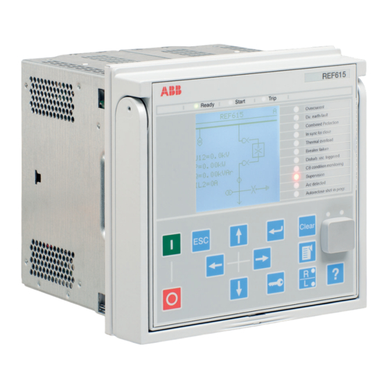
® distributed power generation. REF615 is a member of ABB’s Relion product family and part of its 615 protection and control product series. The 615 series relays are characterized by their compactness and withdrawable-unit design. -
Page 24: Product Version History
Section 2 1MRS756378 S REF615 overview 2.1.1 Product version history Product version Product history Product released • IRIG-B • Support for parallel protocols added: IEC 61850 and Modbus • X130 BIO added: optional for variants B and D • CB interlocking functionality enhanced •... -
Page 25: Pcm600 And Relay Connectivity Package Version
Section 2 1MRS756378 S REF615 overview Product version Product history 4.0 FP1 • High-availability seamless redundancy (HSR) protocol • Parallel redundancy protocol (PRP-1) • Parallel use of IEC 61850 and DNP3 protocols • Parallel use of IEC 61850 and IEC 60870-5-103 protocols •... -
Page 26: Operation Functionality
• AR Sequence Visualizer • Label Printing • IEC 61850 Configuration • IED Configuration Migration Download connectivity packages from the ABB Web site http://www.abb.com/substationautomation or directly with the Update Manager in PCM600. Operation functionality 2.2.1 Optional functions • Arc protection •... - Page 27 Section 2 1MRS756378 S REF615 overview Table 2: Plug-in unit and case Main unit Slot ID Content options Plug-in Small (5 lines, 20 characters) unit Large (10 lines, 20 characters) with SLD Small Chinese (3 lines, 8 or more characters) Large Chinese (7 lines, 8 or more characters) with SLD X100 Auxiliary power/BO...
- Page 28 Section 2 1MRS756378 S REF615 overview Main unit Slot ID Content options Case X130 AI/BI module Only with configurations E, F, H, J, K and N: 3 phase voltage inputs (60-210 V) 1 residual voltage input (60-210 V) 4 binary inputs Additionally with configurations H, J, K and N: 1 reference voltage input for SECRSYN1 (60-210 V) AI/RTD/mA module...
- Page 29 Section 2 1MRS756378 S REF615 overview Table 3: Input/output overview Std. Order code digit Analog channels Binary channels conf. Combi sensor 4 PO AA / AB + 2 SO 4 PO + 9 SO 4 PO AA / AB + 5 SO 4 PO + 6 SO 4 PO...
-
Page 30: Local Hmi
Section 2 1MRS756378 S REF615 overview Std. Order code digit Analog channels Binary channels conf. Combi sensor 4 PO + 6 SO 4 PO + 2 SO 4 PO + 6 SO 4 PO + 2 SO Local HMI The LHMI is used for setting, monitoring and controlling the protection relay. The LHMI comprises the display, buttons, LED indicators and communication port. -
Page 31: Display
Section 2 1MRS756378 S REF615 overview 2.4.1 Display The LHMI includes a graphical display that supports two character sizes. The character size depends on the selected language. The amount of characters and rows fitting the view depends on the character size. Table 4: Small display Rows in the view... -
Page 32: Leds
Section 2 1MRS756378 S REF615 overview 2.4.2 LEDs The LHMI includes three protection indicators above the display: Ready, Start and Trip. There are 11 matrix programmable LEDs on front of the LHMI. The LEDs can be configured with PCM600 and the operation mode can be selected with the LHMI, WHMI or PCM600. - Page 33 Section 2 1MRS756378 S REF615 overview • Programmable LEDs and event lists • System supervision • Parameter settings • Measurement display • Disturbance records • Fault records • Load profile record • Phasor diagram • Single-line diagram • Importing/Exporting parameters •...
-
Page 34: Authorization
Section 2 1MRS756378 S REF615 overview Authorization Four user categories have been predefined for the LHMI and the WHMI, each with different rights and default passwords. The default passwords in the protection relay delivered from the factory can be changed with Administrator user rights. User authorization is disabled by default for LHMI but WHMI always uses authorization. - Page 35 Section 2 1MRS756378 S REF615 overview The protection relay stores 2048 audit trail events to the nonvolatile audit trail. Additionally, 1024 process events are stored in a nonvolatile event list. Both the audit trail and event list work according to the FIFO principle. Nonvolatile memory is based on a memory type which does not need battery backup nor regular component change to maintain the memory storage.
-
Page 36: Communication
Section 2 1MRS756378 S REF615 overview PCM600. The audit trail cannot be reset, but PCM600 Event Viewer can filter data. Audit trail events can be configured to be visible also in LHMI/WHMI Event list together with process related events. To expose the audit trail events through Event list, define the Authority logging level parameter via Configuration/ Authorization/Security. -
Page 37: Self-Healing Ethernet Ring
Section 2 1MRS756378 S REF615 overview communication protocol is supported by using the protocol converter SPA-ZC 302. Operational information and controls are available through these protocols. However, some communication functionality, for example, horizontal communication between the protection relays, is only enabled by the IEC 61850 communication protocol. The IEC 61850 communication implementation supports all monitoring and control functions. -
Page 38: Ethernet Redundancy
Section 2 1MRS756378 S REF615 overview Client A Client B Network A Network B Managed Ethernet switch Managed Ethernet switch with RSTP support with RSTP support GUID-283597AF-9F38-4FC7-B87A-73BFDA272D0F V3 EN Figure 6: Self-healing Ethernet ring solution The Ethernet ring solution supports the connection of up to 30 protection relays. - Page 39 Section 2 1MRS756378 S REF615 overview IEC 62439-3:2012 cancels and replaces the first edition published in 2010. These standard versions are also referred to as IEC 62439-3 Edition 1 and IEC 62439-3 Edition 2. The protection relay supports IEC 62439-3:2012 and it is not compatible with IEC 62439-3:2010. Each PRP node, called a doubly attached node with PRP (DAN), is attached to two independent LANs operated in parallel.
-
Page 40: Process Bus
Section 2 1MRS756378 S REF615 overview • Via an external redundancy box (RedBox) or a switch capable of connecting to PRP and normal networks • By connecting the node directly to LAN A or LAN B as SAN • By connecting the node to the protection relay's interlink port HSR applies the PRP principle of parallel operation to a single ring, treating the two directions as two virtual LANs. - Page 41 Section 2 1MRS756378 S REF615 overview UniGear Digital switchgear concept relies on the process bus together with current and voltage sensors. The process bus enables several advantages for the UniGear Digital like simplicity with reduced wiring, flexibility with data availability to all IEDs, improved diagnostics and longer maintenance cycles.
-
Page 42: Secure Communication
Section 2 1MRS756378 S REF615 overview Primary Secondary IEEE 1588 v2 IEEE 1588 v2 master clock master clock (optional) Managed HSR Managed HSR Ethernet Ethernet switch switch IEC 61850 Backup 1588 master clock GUID-7C56BC1F-F1B2-4E74-AB8E-05001A88D53D V4 EN Figure 10: Example network topology with process bus, redundancy and IEEE 1588 v2 time synchronization The process bus option is available for all 615 series IEDs equipped with phase voltage inputs. -
Page 43: Section 3 Ref615 Standard Configurations
Section 3 1MRS756378 S REF615 standard configurations Section 3 REF615 standard configurations Standard configurations REF615 is available in twelve alternative standard configurations. The standard signal configuration can be altered by means of the signal matrix or the graphical application functionality of the Protection and Control IED Manager PCM600. Further, the application configuration functionality of PCM600 supports the creation of multi-layer logic functions using various logical elements, including timers and flip-flops. - Page 44 Section 3 1MRS756378 S REF615 standard configurations Description Std. conf. Directional and non-directional overcurrent and earth-fault protection, high-impedance restricted earth-fault protection, voltage and frequency based protection and measurements, synchro-check and circuit-breaker condition monitoring (optional power quality and fault locator) Directional and non-directional overcurrent and earth-fault protection with multifrequency neutral admittance, voltage, frequency and power based protection and measurements, and circuit-breaker condition monitoring (sensor inputs, optional power quality, fault locator, interconnetion protection and synchro-check with IEC 61850-9-2 LE)
- Page 45 Section 3 1MRS756378 S REF615 standard configurations Function IEC 61850 Phase discontinuity PDNSPTOC protection Residual overvoltage ROVPTOV protection Three-phase PHPTUV undervoltage protection Three-phase PHPTOV overvoltage protection Positive-sequence PSPTUV undervoltage protection Negative-sequence NSPTOV overvoltage protection Frequency protection FRPFRQ Three-phase thermal T1PTTR protection for feeders, cables and distribution transformers...
- Page 46 Section 3 1MRS756378 S REF615 standard configurations Function IEC 61850 Voltage variation PHQVVR Voltage unbalance VSQVUB Control Circuit-breaker control CBXCBR Disconnector control DCXSWI Earthing switch control ESXSWI Disconnector position DCSXSWI indication Earthing switch ESSXSWI indication Autoreclosing DARREC Synchronism and SECRSYN energizing check Condition monitoring and supervision Circuit-breaker...
-
Page 47: Addition Of Control Functions For Primary Devices And The Use Of Binary Inputs And Outputs
Section 3 1MRS756378 S REF615 standard configurations Function IEC 61850 IEC 61850-9-2 LE SMVRCV sampled value receiving (voltage 8)9) sharing) Other Minimum pulse timer TPGAPC (2 pcs) Minimum pulse timer TPSGAPC (2 pcs, second resolution) Minimum pulse timer TPMGAPC (2 pcs, minute resolution) Pulse timer (8 pcs) PTGAPC... - Page 48 Section 3 1MRS756378 S REF615 standard configurations The suitability of the IED’s binary outputs which have been selected for primary device control should be carefully verified, for example make and carry and breaking capacity. If the requirements for the primary device control circuit are not met, using external auxiliary relays should be considered.
-
Page 49: Connection Diagrams
Section 3 1MRS756378 S REF615 standard configurations Connection diagrams REF615 X120 X100 BI 1 Positive Current Direction BI 2 BI 3 60 - 210V 1/5A 1/5A 1/5A 1/5A X110 BI 1 BI 2 TCS1 BI 3 BI 4 TCS2 BI 5 X110 BI 6 BI 7... - Page 50 Section 3 1MRS756378 S REF615 standard configurations REF615 Positive Current Direction X120 X100 BI 1 BI 2 BI 3 BI 4 1/5A 1/5A 1/5A 1/5A X110 BI 1 BI 2 TCS1 BI 3 BI 4 TCS2 BI 5 X110 BI 6 BI 7 BI 8 X130...
- Page 51 Section 3 1MRS756378 S REF615 standard configurations GUID-F7601942-ACF2-47E2-8F21-CD9C1D2BC1F0 V4 EN Figure 13: Connection diagram for the E and F configurations REF615 Application Manual...
- Page 52 Section 3 1MRS756378 S REF615 standard configurations REF615 X130 X100 Positive Current 0,2/1A Direction X131 X132 X133 TCS1 X110 BI 1 TCS2 BI 2 X110 BI 3 BI 4 BI 5 BI 6 BI 7 BI 8 Light sensor input 1 Light sensor input 2 1) Optional 2) BIO0005 Module (8BI+4BO)
- Page 53 Section 3 1MRS756378 S REF615 standard configurations GUID-E8E2F79F-3DD8-46BD-8DE7-87A30133A7AE V1 EN Figure 15: Connection diagram for the H, J and N configurations REF615 Application Manual...
- Page 54 Section 3 1MRS756378 S REF615 standard configurations REF615 X130 X100 BI 1 BI 2 BI 3 BI 4 60 - 210V U12B (for SECRSYN1) 60 - 210V 60 - 210V 60 - 210V 60 - 210V X120 Positive 1/5A Current not in use Direction TCS1...
-
Page 55: Standard Configuration A
Section 3 1MRS756378 S REF615 standard configurations Standard configuration A 3.3.1 Applications The standard configuration for non-directional overcurrent and directional earth-fault protection is mainly intended for cable and overhead-line feeder applications in isolated and resonant-earthed distribution networks. The configuration also includes additional options for selecting earth-fault protection based on admittance or wattmetric-based principles. -
Page 56: Functions
Section 3 1MRS756378 S REF615 standard configurations 3.3.2 Functions REF615 FEEDER PROTECTION AND CONTROL RELAY STANDARD CONFIGURATION PROTECTION LOCAL HMI ALSO AVAILABLE - Disturbance and fault recorders 2× - Event log and recorded data Master Trip - Local/Remote push button on LHMI Configuration System Lockout relay... -
Page 57: Default Disturbance Recorder Settings
Section 3 1MRS756378 S REF615 standard configurations Table 12: Default connections for binary outputs Binary output Description X100-PO1 Close circuit breaker X100-PO2 Circuit breaker failure protection trip to upstream breaker X100-PO3 Open circuit breaker/trip coil 1 X100-PO4 Open circuit breaker/trip coil 2 X100-SO1 General start indication X100-SO2... - Page 58 Section 3 1MRS756378 S REF615 standard configurations Table 15: Default disturbance recorder binary channels Channel ID text Level trigger mode PHLPTOC1 - start Positive or Rising PHHPTOC1 - start Positive or Rising PHHPTOC2 - start Positive or Rising PHIPTOC1 - start Positive or Rising NSPTOC1 - start Positive or Rising...
-
Page 59: Functional Diagrams
Section 3 1MRS756378 S REF615 standard configurations Channel ID text Level trigger mode INTRPTEF1 - operate Level trigger off EFHPTOC1 - operate Level trigger off PDNSPTOC1 - operate Level trigger off INRPHAR1 - blk2h Level trigger off T1PTTR1 - operate Level trigger off ROVPTOV1 - operate Level trigger off... -
Page 60: Functional Diagrams For Protection
Section 3 1MRS756378 S REF615 standard configurations Depending on the communication protocol the required function block needs to be instantiated in the configuration. 3.3.3.1 Functional diagrams for protection The functional diagrams describe the IEDs protection functionality in detail and according to the factory set default connections. Four overcurrent stages are offered for overcurrent and short-circuit protection. - Page 61 Section 3 1MRS756378 S REF615 standard configurations Two negative-sequence overcurrent protection stages NSPTOC1 and NSPTOC2 are provided for phase unbalance protection. These functions are used to protect the feeder against phase unbalance. NSPTOC1 BLOCK OPERATE NSPTOC1_OPERATE ENA_MULT START NSPTOC1_START NSPTOC2 BLOCK OPERATE NSPTOC2_OPERATE...
- Page 62 Section 3 1MRS756378 S REF615 standard configurations DEFLPDEF1 BLOCK OPERATE DEFLPDEF1_OPERATE ENA_MULT START DEFLPDEF1_START RCA_CTL DEFLPDEF2 BLOCK OPERATE DEFLPDEF2_OPERATE ENA_MULT START DEFLPDEF2_START RCA_CTL DEFHPDEF1 BLOCK OPERATE DEFHPDEF1_OPERATE ENA_MULT START DEFHPDEF1_START RCA_CTL DEFLPDEF1_OPERATE DEF_OPERATE DEFLPDEF2_OPERATE DEFHPDEF1_OPERATE GUID-3499F814-CAB8-4310-9428-D3B72A9BEAF3 V1 EN Figure 21: Directional earth-fault protection functions INTRPTEF1 BLOCK...
- Page 63 Section 3 1MRS756378 S REF615 standard configurations WPWDE1 BLOCK OPERATE WPWDE1_OPERATE RCA_CTL START WPWDE1_START WPWDE2 BLOCK OPERATE WPWDE2_OPERATE RCA_CTL START WPWDE2_START WPWDE3 BLOCK OPERATE WPWDE3_OPERATE RCA_CTL START WPWDE3_START WPWDE1_OPERATE WPWDE_OPERATE WPWDE2_OPERATE WPWDE3_OPERATE GUID-2EE794AD-2D14-49C7-AD33-89F75627AEA1 V1 EN Figure 23: Wattmetric protection function EFPADM1 BLOCK OPERATE...
- Page 64 Section 3 1MRS756378 S REF615 standard configurations Non-directional (cross-country) earth-fault protection, using calculated Io, EFHPTOC1 protects against double earth-fault situations in isolated or compensated networks. This protection function uses the calculated residual current originating from the phase currents. EFHPTOC1 BLOCK OPERATE EFHPTOC1_OPERATE ENA_MULT...
- Page 65 Section 3 1MRS756378 S REF615 standard configurations CCBRBRF1 BLOCK CB_FAULT_AL START TRBU PHIPTOC1_OPERATE CCBRBRF1_TRBU POSCLOSE TRRET PHHPTOC1_OPERATE CCBRBRF1_TRRET CB_FAULT PHHPTOC2_OPERATE DEFHPDEF1_OPERATE DEFLPDEF2_OPERATE X120_BI2_CB_CLOSED GUID-434D2001-0D44-45D6-863F-DD1663FCE6C0 V1 EN Figure 28: Circuit breaker failure protection function Three arc protection ARCSARC1...3 stages are included as an optional function. The arc protection offers individual function blocks for three arc sensors that can be connected to the IED.
- Page 66 Section 3 1MRS756378 S REF615 standard configurations The optional autoreclosing function is configured to be initiated by operate signals from a number of protection stages through the INIT_1...5 inputs. It is possible to create individual autoreclose sequences for each input. The autoreclosing function can be inhibited with the INHIBIT_RECL input.
- Page 67 Section 3 1MRS756378 S REF615 standard configurations Residual overvoltage protection ROVPTOV1 provides earth-fault protection by detecting an abnormal level of residual voltage. This can be used, for example, as a nonselective backup protection for the selective directional earth-fault functionality. ROVPTOV1 BLOCK OPERATE ROVPTOV1_OPERATE...
- Page 68 Section 3 1MRS756378 S REF615 standard configurations PHLPTOC1_START PHHPTOC1_START PHHPTOC2_START PHIPTOC1_START NSPTOC1_START NSPTOC2_START DEFLPDEF1_START DEFLPDEF2_START DEFHPDEF1_START TPGAPC1 OUT1 GENERAL_START_PULSE OUT2 GENERAL_OPERATE_PULSE INTRPTEF1_START EFHPTOC1_START PDNSPTOC1_START ROVPTOV1_START ROVPTOV2_START ROVPTOV3_START PHLPTOC1_OPERATE PHHPTOC1_OPERATE PHHPTOC2_OPERATE PHIPTOC1_OPERATE NSPTOC1_OPERATE NSPTOC2_OPERATE DEFLPDEF1_OPERATE DEFLPDEF2_OPERATE DEFHPDEF1_OPERATE INTRPTEF1_OPERATE EFHPTOC1_OPERATE PDNSPTOC1_OPERATE ROVPTOV1_OPERATE ROVPTOV2_OPERATE ROVPTOV3_OPERATE ARCSARC1_OPERATE...
- Page 69 Section 3 1MRS756378 S REF615 standard configurations TRPPTRC1 BLOCK TRIP TRPPTRC1_TRIP OPERATE CL_LKOUT PHIPTOC1_OPERATE RST_LKOUT PHLPTOC1_OPERATE PHHPTOC1_OPERATE PHHPTOC2_OPERATE NSPTOC1_OPERATE NSPTOC2_OPERATE DEFHPDEF1_OPERATE DEFLPDEF1_OPERATE DEFLPDEF2_OPERATE EFPADM1_OPERATE EFPADM2_OPERATE EFPADM3_OPERATE INTRPTEF1_OPERATE EFHPTOC1_OPERATE PDNSPTOC1_OPERATE ROVPTOV1_OPERATE ROVPTOV2_OPERATE ROVPTOV3_OPERATE WPWDE1_OPERATE WPWDE2_OPERATE WPWDE3_OPERATE ARCSARC1_OPERATE ARCSARC2_OPERATE ARCSARC3_OPERATE GUID-74DA3CAA-F877-4C2E-9390-F444EA6B5F6C V1 EN Figure 33: Trip logic TRPPTRC1 REF615...
-
Page 70: Functional Diagrams For Disturbance Recorder
Section 3 1MRS756378 S REF615 standard configurations TRPPTRC2 BLOCK TRIP TRPPTRC2_TRIP OPERATE CL_LKOUT PHIPTOC1_OPERATE RST_LKOUT PHLPTOC1_OPERATE PHHPTOC1_OPERATE PHHPTOC2_OPERATE NSPTOC1_OPERATE NSPTOC2_OPERATE DEFHPDEF1_OPERATE DEFLPDEF1_OPERATE DEFLPDEF2_OPERATE EFPADM1_OPERATE EFPADM2_OPERATE EFPADM3_OPERATE INTRPTEF1_OPERATE EFHPTOC1_OPERATE PDNSPTOC1_OPERATE ROVPTOV1_OPERATE ROVPTOV2_OPERATE ROVPTOV3_OPERATE CCBRBRF1_TRRET WPWDE1_OPERATE WPWDE2_OPERATE WPWDE3_OPERATE ARCSARC1_OPERATE ARCSARC2_OPERATE ARCSARC3_OPERATE GUID-AF276C39-F671-459C-9472-7243985B578A V1 EN Figure 34: Trip logic TRPPTRC2 3.3.3.2... -
Page 71: Functional Diagrams For Condition Monitoring
Section 3 1MRS756378 S REF615 standard configurations RDRE1 DEFLPDEF1_START WPWDE1_START TRIGGERED DISTURB_RECORD_TRIGGERED PHLPTOC1_START EFPADM1_START PHHPTOC1_START PHHPTOC2_START PHIPTOC1_START NSPTOC1_START NSPTOC2_START INTRPTEF1_START EFHPTOC1_START DEFLPDEF2_START PDNSPTOC1_START WPWDE2_START T1PTTR1_START EFPADM2_START ROVPTOV1_START ROVPTOV2_START PHIPTOC1_OPERATE ROVPTOV3_START PHHPTOC1_OPERATE CCBRBRF1_TRRET PHHPTOC2_OPERATE CCBRBRF1_TRBU PHLPTOC1_OPERATE INTRPTEF1_OPERATE EFHPTOC1_OPERATE DEFHPDEF1_START PDNSPTOC1_OPERATE WPWDE3_START INRPHAR1_BLK2H EFPADM3_START T1PTTR1_OPERATE... -
Page 72: Functional Diagrams For Control And Interlocking
Section 3 1MRS756378 S REF615 standard configurations TCSSCBR1 BLOCK ALARM TCSSCBR_BLOCKING TCSSCBR1_ALARM TCSSCBR2 BLOCK ALARM TCSSCBR_BLOCKING TCSSCBR2_ALARM TCSSCBR1_ALARM TCSSCBR_ALARM TCSSCBR2_ALARM GUID-F6281256-8B8D-41D9-AD19-014D604AFCEC V1 EN Figure 36: Trip circuit supervision function TRPPTRC1_TRIP TCSSCBR_BLOCKING TRPPTRC2_TRIP X120_BI3_CB_OPENED GUID-F0B3AFC4-7D62-49A3-BF0D-AD03041EA78D V1 EN Figure 37: Logic for blocking of trip circuit supervision 3.3.3.4 Functional diagrams for control and interlocking The circuit breaker closing is enabled when the ENA_CLOSE input is activated. - Page 73 Section 3 1MRS756378 S REF615 standard configurations CBXCBR1_EXE_CL CB_CLOSE_COMMAND DARREC1_CLOSE_CB GUID-186FE757-E2ED-483B-A0F9-7CF97278BC0C V1 EN Figure 39: Circuit breaker control logic: Signals for the closing coil of circuit breaker 1 TRPPTRC1_TRIP CB_OPEN_COMMAND CBXCBR1_EXE_OP DARREC1_OPEN_CB GUID-F8B92F5F-5A07-491D-8376-9167A9D69DC1 V1 EN Figure 40: Circuit breaker control logic: Signals for the opening coil of circuit breaker 1 TRPPTRC1_TRIP CBXCBR1_ENA_CLOSE...
-
Page 74: Functional Diagrams For Measurement Functions
Section 3 1MRS756378 S REF615 standard configurations 3.3.3.5 Functional diagrams for measurement functions The phase current inputs to the IED are measured by the three-phase current measurement function CMMXU1. The current input is connected to the X120 card in the back panel. Similarly, the sequence current measurement CSMSQI1 measures the sequence current and the residual current measurement RESCMMXU1 measures the residual current. -
Page 75: Functional Diagrams For I/O And Alarm Leds
Section 3 1MRS756378 S REF615 standard configurations 3.3.3.6 Functional diagrams for I/O and alarm LEDs X120_BI1_EXT_OC_BLOCKING X120 (AIM).X120-Input 1 X120_BI2_CB_CLOSED X120 (AIM).X120-Input 2 X120_BI3_CB_OPENED X120 (AIM).X120-Input 3 GUID-1CC3270B-3A49-43C1-8C2F-0DFAF37FAD58 V1 EN Figure 49: Default binary inputs - X120 CB_CLOSE_COMMAND X100 (PSM).X100-PO1 CCBRBRF1_TRBU X100 (PSM).X100-PO2 GENERAL_START_PULSE... - Page 76 Section 3 1MRS756378 S REF615 standard configurations LED1 ALARM PHxPTOC_OPERATE RESET LED2 ALARM DEF_OPERATE RESET EFPADM_OPERATE WPWDE_OPERATE INTRPTEF1_OPERATE LED3 ALARM EFHPTOC1_OPERATE RESET ROVPTOV_OPERATE LED4 ALARM NSPTOC_OPERATE RESET PDNSPTOC1_OPERATE LED5 ALARM T1PTTR1_ALARM RESET GUID-E32FB298-A762-4D91-9134-2AD11BA1B12F V1 EN REF615 Application Manual...
-
Page 77: Other Functions
Section 3 1MRS756378 S REF615 standard configurations LED6 ALARM CCBRBRF1_TRBU RESET LED7 ALARM DISTURB_RECORD_TRIGGERED RESET LED9 ALARM TCSSCBR_ALARM RESET LED10 ALARM ARCSARC_OPERATE RESET LED11 ALARM DARREC1_INPRO RESET GUID-781E66E9-CE48-4DA6-8159-86BED9295D7C V1 EN Figure 51: Default LED connection 3.3.3.7 Other functions The configuration includes few instances of multipurpose protection function MAPGAPC, runtime counter for machines and devices MDSOPT and different types of timer functions. -
Page 78: Functions
Section 3 1MRS756378 S REF615 standard configurations signal designation within the IED enables this configuration to be further adapted to different primary circuit layouts and the related functionality needs by modifying the internal functionality using PCM600. 3.4.2 Functions REF615 FEEDER PROTECTION AND CONTROL RELAY STANDARD CONFIGURATION PROTECTION... - Page 79 Section 3 1MRS756378 S REF615 standard configurations Table 16: Default connections for binary inputs Binary input Description X110-BI2 Directional earth-fault protection's basic angle control X110-BI3 Circuit breaker low gas pressure indication X110-BI4 Circuit breaker spring charged indication X110-BI5 Circuit breaker truck in (service position) indication X110-BI6 Circuit breaker truck out (test position) indication X110-BI7...
-
Page 80: Default Disturbance Recorder Settings
Section 3 1MRS756378 S REF615 standard configurations Description Trip circuit supervision alarm Arc protection operate Autoreclose in progress 3.4.2.2 Default disturbance recorder settings Table 19: Default disturbance recorder analog channels Channel Description Table 20: Default disturbance recorder binary channels Channel ID text Level trigger mode PHLPTOC1 - start... - Page 81 Section 3 1MRS756378 S REF615 standard configurations Channel ID text Level trigger mode EFHPTOC1 - start Positive or Rising PDNSPTOC1 - start Positive or Rising T1PTTR1 - start Positive or Rising ROVPTOV1 - start Positive or Rising ROVPTOV2 - start Positive or Rising ROVPTOV3 - start Positive or Rising...
-
Page 82: Functional Diagrams
Section 3 1MRS756378 S REF615 standard configurations Channel ID text Level trigger mode DARREC1 - unsuc recl Level trigger off X120BI1 - ext OC blocking Level trigger off X120BI2 - CB closed Level trigger off X120BI3 - CB opened Level trigger off 3.4.3 Functional diagrams The functional diagrams describe the default input, output, alarm LED and function-... - Page 83 Section 3 1MRS756378 S REF615 standard configurations PHIPTOC1 BLOCK OPERATE X120_BI1_EXT_OC_BLOCKING PHIPTOC1_OPERATE ENA_MULT START PHIPTOC1_START PHHPTOC1 BLOCK OPERATE PHHPTOC1_OPERATE ENA_MULT START PHHPTOC1_START PHHPTOC2 BLOCK OPERATE PHHPTOC2_OPERATE ENA_MULT START PHHPTOC2_START PHLPTOC1 BLOCK OPERATE PHLPTOC1_OPERATE ENA_MULT START PHLPTOC1_START PHIPTOC1_OPERATE PHxPTOC_OPERATE PHHPTOC1_OPERATE PHHPTOC2_OPERATE PHLPTOC1_OPERATE GUID-421CC220-9CDA-4862-A705-52A7C7E39DF0 V1 EN Figure 53:...
- Page 84 Section 3 1MRS756378 S REF615 standard configurations INRPHAR1 BLOCK BLK2H INRPHAR1_BLK2H GUID-ED765A4F-9F2B-4546-BE25-269CBABC0F9D V1 EN Figure 55: Inrush detector function Two negative-sequence overcurrent protection stages NSPTOC1 and NSPTOC2 are provided for phase unbalance protection. These functions are used to protect the feeder against phase unbalance.
- Page 85 Section 3 1MRS756378 S REF615 standard configurations DEFLPDEF1 BLOCK OPERATE DEFLPDEF1_OPERATE ENA_MULT START DEFLPDEF1_START RCA_CTL X110_BI2_RCA_CONTROL DEFLPDEF2 BLOCK OPERATE DEFLPDEF2_OPERATE ENA_MULT START DEFLPDEF2_START RCA_CTL X110_BI2_RCA_CONTROL DEFHPDEF1 BLOCK OPERATE DEFHPDEF1_OPERATE ENA_MULT START DEFHPDEF1_START RCA_CTL X110_BI2_RCA_CONTROL DEFLPDEF1_OPERATE DEFxPDEF_OPERATE DEFLPDEF2_OPERATE DEFHPDEF1_OPERATE GUID-27CCBD30-6092-47C7-B753-18A7413E4B77 V1 EN Figure 57: Directional earth-fault protection functions INTRPTEF1...
- Page 86 Section 3 1MRS756378 S REF615 standard configurations WPWDE1 BLOCK OPERATE WPWDE1_OPERATE RCA_CTL START WPWDE1_START WPWDE2 BLOCK OPERATE WPWDE2_OPERATE RCA_CTL START WPWDE2_START WPWDE3 BLOCK OPERATE WPWDE3_OPERATE RCA_CTL START WPWDE3_START WPWDE1_OPERATE WPWDE_OPERATE WPWDE2_OPERATE WPWDE3_OPERATE GUID-A26E1E55-4059-462C-942F-F508E4653100 V1 EN Figure 59: Wattmetric protection function EFPADM1 BLOCK OPERATE...
- Page 87 Section 3 1MRS756378 S REF615 standard configurations A dedicated non-directional earth-fault protection block EFHPTOC protects from double earth-fault situations in isolated or compensated networks. The protection function uses the calculated residual current originating from the phase currents. EFHPTOC1 BLOCK OPERATE EFHPTOC1_OPERATE ENA_MULT START...
- Page 88 Section 3 1MRS756378 S REF615 standard configurations Three arc protection ARCSARC1...3 stages are included as an optional function. The arc protection offers individual function blocks for three arc sensors that can be connected to the IED. Each arc protection function block has two different operation modes, that is, with or without the phase and residual current check.
- Page 89 Section 3 1MRS756378 S REF615 standard configurations ARCSARC1 BLOCK OPERATE ARCSARC1_OPERATE REM_FLT_ARC ARC_FLT_DET ARCSARC1_ARC_FLT_DET OPR_MODE ARCSARC2 BLOCK OPERATE ARCSARC2_OPERATE REM_FLT_ARC ARC_FLT_DET ARCSARC2_ARC_FLT_DET OPR_MODE ARCSARC3 BLOCK OPERATE ARCSARC3_OPERATE REM_FLT_ARC ARC_FLT_DET ARCSARC3_ARC_FLT_DET OPR_MODE ARCSARC1_OPERATE ARCSARC_OPERATE ARCSARC2_OPERATE ARCSARC3_OPERATE GUID-D5676839-45F1-40BB-A553-E3C4A0A1E1A0 V1 EN TRPPTRC3 BLOCK TRIP TRPPTRC3_TRIP OPERATE...
- Page 90 Section 3 1MRS756378 S REF615 standard configurations The circuit breaker availability for the autoreclosing sequence is expressed with the CB_READY input in DARREC1. The signal, and other required signals, are connected to the CB spring charged binary inputs in this configuration. The open command from the autorecloser is connected directly to the binary output X100:PO3, whereas the close command is connected directly to the binary output X100:PO1.
- Page 91 Section 3 1MRS756378 S REF615 standard configurations ROVPTOV1 BLOCK OPERATE ROVPTOV1_OPERATE START ROVPTOV1_START ROVPTOV2 BLOCK OPERATE ROVPTOV2_OPERATE START ROVPTOV2_START ROVPTOV3 BLOCK OPERATE ROVPTOV3_OPERATE START ROVPTOV3_START ROVPTOV1_OPERATE ROVPTOV_OPERATE ROVPTOV2_OPERATE ROVPTOV3_OPERATE GUID-23A63895-A476-4096-BD6D-D0CE711EEC5D V1 EN Figure 67: Residual voltage protection function General start and operate from all the functions are connected to minimum pulse timer TPGAPC for setting the minimum pulse length for the outputs.
-
Page 92: Functional Diagrams For Disturbance Recorder
Section 3 1MRS756378 S REF615 standard configurations assigned to RST_LKOUT input of both the trip logic to enable external reset with a push button. Three other trip logics TRPPTRC3...4 are also available if the IED is ordered with high speed binary outputs options. TRPPTRC1 BLOCK TRIP... -
Page 93: Functional Diagrams For Condition Monitoring
Section 3 1MRS756378 S REF615 standard configurations depending on the parameter settings. Additionally, the selected signals from different functions and few binary inputs are also connected. DEFLPDEF1_START RDRE1 WPWDE1_START TRIGGERED EFPADM1_START PHLPTOC1_START DISTURB_RECORD_TRIGGERED PHHPTOC1_START PHHPTOC2_START PHIPTOC1_START NSPTOC1_START NSPTOC2_START INTRPTEF1_START DEFLPDEF2_START EFHPTOC1_START WPWDE2_START PDNSPTOC1_START... - Page 94 Section 3 1MRS756378 S REF615 standard configurations SSCBR1_TRV_T_OP_ALM SSCBR1_TRV_T_CL_ALM SSCBR1_SPR_CHR_ALM SSCBR1_OPR_ALM SSCBR1_OPR_LO SSCBR1_IPOW_ALM SSCBR1_ALARMS SSCBR1_IPOW_LO SSCBR1_CB_LIFE_ALM SSCBR1_MON_ALM SSCBR1_PRES_ALM SSCBR1_PRES_LO GUID-ED84A0BD-A150-4BBA-8A82-8AC4B3CAE673 V1 EN Figure 73: Logic for circuit breaker monitoring alarm X110_BI4_CB_SPRING_CHARGED CB_SPRING_DISCHARGED GUID-7B9FF17E-827E-40A4-B1D2-F13E236D0381 V1 EN Figure 74: Logic for start of circuit breaker spring charging Two separate trip circuit supervision functions are included, TCSSCBR1 for power output X100:PO3 and TCSSCBR2 for power output X100:PO4.
-
Page 95: Functional Diagrams For Control And Interlocking
Section 3 1MRS756378 S REF615 standard configurations TCSSCBR1 BLOCK ALARM TCSSCBR_BLOCKING TCSSCBR1_ALARM TCSSCBR2 BLOCK ALARM TCSSCBR_BLOCKING TCSSCBR2_ALARM TCSSCBR1_ALARM TCSSCBR_ALARM TCSSCBR2_ALARM GUID-0B65C9FD-DEB8-4895-82A8-725A1A3E7896 V1 EN Figure 75: Trip circuit supervision function TRPPTRC1_TRIP TCSSCBR_BLOCKING TRPPTRC2_TRIP X120_BI3_CB_OPENED GUID-22D4A3A4-01E4-4EDD-A9A9-FB31F956B9A2 V1 EN Figure 76: Logic for blocking of trip circuit supervision function 3.4.3.4 Functional diagrams for control and interlocking Two types of disconnector and earthing switch function blocks are available. - Page 96 Section 3 1MRS756378 S REF615 standard configurations disconnector or breaker truck and earth-switch position status, status of the trip logics, gas pressure alarm and circuit-breaker spring charging status. The OKPOS output from DCSXSWI defines whether the disconnector or breaker truck is either open (in test position) or close (in service position). This output, together with the open earth-switch and non-active trip signals, activates the close- enable signal to the circuit breaker control function block.
-
Page 97: Functional Diagrams For Measurement Functions
Section 3 1MRS756378 S REF615 standard configurations AND6 TRPPTRC1_TRIP CBXCBR1_ENA_CLOSE TRPPTRC2_TRIP X110_BI3_GAS_PRESSURE_ALARM DCSXSWI1_OKPOS ESSXSWI1_OPENPOS X110_BI4_CB_SPRING_CHARGED GUID-3C981DB3-EFC0-490C-AE96-2C5B16CC7E00 V1 EN Figure 82: Circuit breaker close enable logic The configuration includes logic for generating circuit breaker external closing and opening command with the IED in local or remote mode. Check the logic for the external circuit breaker closing command and modify it according to the application. - Page 98 Section 3 1MRS756378 S REF615 standard configurations The residual voltage input is connected to the X120 card in the back panel and is measured by the residual voltage measurement RESVMMXU1. The measurements can be seen from the LHMI and they are available under the measurement option in the menu selection.
-
Page 99: Functional Diagrams For I/O And Alarm Leds
Section 3 1MRS756378 S REF615 standard configurations 3.4.3.6 Functional diagrams for I/O and alarm LEDs X110 (BIO).X110-Input 2 X110_BI2_RCA_CONTROL X110 (BIO-H).X110-Input 2 X110 (BIO).X110-Input 3 X110_BI3_GAS_PRESSURE_ALARM X110 (BIO-H).X110-Input 3 X110 (BIO).X110-Input 4 X110_BI4_CB_SPRING_CHARGED X110 (BIO-H).X110-Input 4 X110 (BIO).X110-Input 5 X110_BI5_CB_TRUCK_IN_SERVICE X110 (BIO-H).X110-Input 5 X110 (BIO).X110-Input 6 X110_BI6_CB_TRUCK_IN_TEST... - Page 100 Section 3 1MRS756378 S REF615 standard configurations UPSTEAM_OC_BLOCKING X110 (BIO).X110-SO1 TRPPTRC3_TRIP X110 (BIO-H).X110-HSO1 OC_OPERATE_PULSE X110 (BIO).X110-SO2 TRPPTRC4_TRIP X110 (BIO-H).X110-HSO2 EF_OPERATE_PULSE X110 (BIO).X110-SO3 TRPPTRC5_TRIP X110 (BIO-H).X110-HSO3 GUID-3A0C4EDB-878A-4282-86B2-894775BBEEE5 V2 EN Figure 93: Default binary outputs - X110 CB_CLOSE_COMMAND X100 (PSM).X100-PO1 CCBRBRF1_TRBU X100 (PSM).X100-PO2 GENERAL_START_PULSE X100 (PSM).X100-SO1 GENERAL_OPERATE_PULSE...
- Page 101 Section 3 1MRS756378 S REF615 standard configurations LED1 ALARM PHxPTOC_OPERATE RESET LED2 ALARM DEF_OPERATE RESET EFPADM_OPERATE WPWDE_OPERATE INTRPTEF1_OPERATE LED3 ALARM EFHPTOC1_OPERATE RESET ROVPTOV_OPERATE LED4 ALARM NSPTOC_OPERATE RESET PDNSPTOC1_OPERATE LED5 ALARM T1PTTR1_ALARM RESET GUID-CD2C4F23-C15B-4A9A-8DB8-A7B862A221D7 V1 EN REF615 Application Manual...
-
Page 102: Functional Diagrams For Other Timer Logics
Section 3 1MRS756378 S REF615 standard configurations LED6 ALARM CCBRBRF1_TRBU RESET LED7 ALARM DISTURB_RECORD_TRIGGERED RESET LED8 ALARM SSCBR1_ALARMS RESET LED9 ALARM TCSSCBR_ALARM RESET LED10 ALARM ARCSARC_OPERATE RESET LED11 ALARM DARREC1_INPRO RESET GUID-5545434B-1C8A-45A3-992C-567617DAE58A V1 EN Figure 95: Default LED connection 3.4.3.7 Functional diagrams for other timer logics The configuration also includes the overcurrent operate and earth-fault operate logic. -
Page 103: Other Functions
Section 3 1MRS756378 S REF615 standard configurations 3.4.3.8 Other functions The configuration includes few instances of multipurpose protection function MAPGAPC, high-impedance fault detection function PHIZ, runtime counter for machines and devices MDSOPT and different types of timers and control functions. These functions are not included in application configuration but they can be added based on the system requirements. -
Page 104: Functions
Section 3 1MRS756378 S REF615 standard configurations 3.5.2 Functions REF615 FEEDER PROTECTION AND CONTROL RELAY STANDARD CONFIGURATION PROTECTION LOCAL HMI ALSO AVAILABLE - Disturbance and fault recorders 2× - Event log and recorded data Master Trip - Local/Remote push button on LHMI Configuration System Lockout relay... -
Page 105: Default Disturbance Recorder Settings
Section 3 1MRS756378 S REF615 standard configurations Table 21: Default connections for binary inputs Binary input Description X120-BI1 Blocking of overcurrent instantaneous stage X120-BI2 Circuit breaker closed indication X120-BI3 Circuit breaker open indication X120-BI4 Reset of master trip lockout Table 22: Default connections for binary outputs Binary output Description... - Page 106 Section 3 1MRS756378 S REF615 standard configurations Channel Description Table 25: Default disturbance recorder binary channels Channel ID text Level trigger mode PHLPTOC1 - start Positive or Rising PHHPTOC1 - start Positive or Rising PHHPTOC2 - start Positive or Rising PHIPTOC1 - start Positive or Rising NSPTOC1 - start...
-
Page 107: Functional Diagrams
Section 3 1MRS756378 S REF615 standard configurations Channel ID text Level trigger mode INRPHAR1 - blk2h Level trigger off T1PTTR1 - operate Level trigger off ARCSARC1 - ARC flt det Level trigger off ARCSARC2 - ARC flt det ARCSARC3 - ARC flt det ARCSARC1 - operate Positive or Rising ARCSARC2 - operate... - Page 108 Section 3 1MRS756378 S REF615 standard configurations PHIPTOC1 BLOCK OPERATE X120_BI1_EXT_OC_BLOCKING PHIPTOC1_OPERATE ENA_MULT START PHIPTOC1_START PHHPTOC1 BLOCK OPERATE PHHPTOC1_OPERATE ENA_MULT START PHHPTOC1_START PHHPTOC2 BLOCK OPERATE PHHPTOC2_OPERATE ENA_MULT START PHHPTOC2_START PHLPTOC1 BLOCK OPERATE PHLPTOC1_OPERATE ENA_MULT START PHLPTOC1_START PHIPTOC1_OPERATE PHxPTOC_OPERATE PHHPTOC1_OPERATE PHHPTOC2_OPERATE PHLPTOC1_OPERATE GUID-FED7D122-DE13-4004-8273-906D289F7EBA V1 EN Figure 98:...
- Page 109 Section 3 1MRS756378 S REF615 standard configurations NSPTOC1 BLOCK OPERATE NSPTOC1_OPERATE ENA_MULT START NSPTOC1_START NSPTOC2 BLOCK OPERATE NSPTOC2_OPERATE ENA_MULT START NSPTOC2_START NSPTOC1_OPERATE NSPTOC_OPERATE NSPTOC2_OPERATE GUID-A0E1F246-E42C-4732-B0DE-BDC3F4A16CDC V1 EN Figure 100: Negative sequence overcurrent protection function Four stages are provided for non-directional earth-fault protection. One stage is dedicated to sensitive earth-fault protection EFLPTOC2.
- Page 110 Section 3 1MRS756378 S REF615 standard configurations Phase discontinuity protection PDNSPTOC1 protects from interruptions in the normal three-phase load supply, for example, in downed conductor situations. PDNSPTOC1 BLOCK OPERATE PDNSPTOC1_OPERATE START PDNSPTOC1_START GUID-72DBEEFC-1AD7-4930-A949-A340CF2767AA V1 EN Figure 103: Phase discontinuity protection Three-phase thermal protection for feeders, cables and distribution transformers T1PTTR1 detects overloads under varying load conditions.
- Page 111 Section 3 1MRS756378 S REF615 standard configurations ARCSARC1 BLOCK OPERATE ARCSARC1_OPERATE REM_FLT_ARC ARC_FLT_DET ARCSARC1_ARC_FLT_DET OPR_MODE ARCSARC2 BLOCK OPERATE ARCSARC2_OPERATE REM_FLT_ARC ARC_FLT_DET ARCSARC2_ARC_FLT_DET OPR_MODE ARCSARC3 BLOCK OPERATE ARCSARC3_OPERATE REM_FLT_ARC ARC_FLT_DET ARCSARC3_ARC_FLT_DET OPR_MODE ARCSARC1_OPERATE ARCSARC_OPERATE ARCSARC2_OPERATE ARCSARC3_OPERATE GUID-2E27AA26-07BE-410A-9BB4-FDF62B54D644 V1 EN Figure 106: Arc protection The optional autoreclosing function is configured to be initiated by operate signals from a number of protection stages through the INIT_1...5 inputs.
- Page 112 Section 3 1MRS756378 S REF615 standard configurations DARREC1 INIT_1 OPEN_CB PHIPTOC1_OPERATE DARREC1_OPEN_CB INIT_2 CLOSE_CB PHHPTOC2_OPERATE DARREC1_CLOSE_CB INIT_3 CMD_WAIT PHHPTOC1_OPERATE INIT_4 INPRO EFLPTOC1_OPERATE DARREC1_INPRO INIT_5 LOCKED EFHPTOC1_OPERATE INIT_6 PROT_CRD DEL_INIT_2 UNSUC_RECL DARREC1_UNSUC_RECL DEL_INIT_3 AR_ON DEL_INIT_4 READY BLK_RECL_T ACTIVE BLK_RCLM_T BLK_THERM CB_POS X120_BI3_CB_OPENED CB_READY INC_SHOTP...
-
Page 113: Functional Diagrams For Disturbance Recorder
Section 3 1MRS756378 S REF615 standard configurations TRPPTRC1 BLOCK TRIP TRPPTRC1_TRIP PHIPTOC1_OPERATE OPERATE CL_LKOUT PHLPTOC1_OPERATE RST_LKOUT PHHPTOC1_OPERATE PHHPTOC2_OPERATE NSPTOC1_OPERATE NSPTOC2_OPERATE EFLPTOC1_OPERATE EFHPTOC1_OPERATE EFIPTOC1_OPERATE EFLPTOC2_OPERATE PDNSPTOC1_OPERATE ARCSARC1_OPERATE ARCSARC2_OPERATE ARCSARC3_OPERATE X120_BI4_RST_LOCKOUT GUID-EF986953-A224-44E3-974B-6AD5E269FB2B V1 EN Figure 109: Trip logic TRPPTRC1 TRPPTRC2 BLOCK TRIP TRPPTRC2_TRIP OPERATE CL_LKOUT... -
Page 114: Functional Diagrams For Condition Monitoring
Section 3 1MRS756378 S REF615 standard configurations RDRE1 TRIGGERED DISTURB_RECORD_TRIGGERED PHLPTOC1_START PHHPTOC1_START PHHPTOC2_START PHIPTOC1_START NSPTOC1_START NSPTOC2_START EFLPTOC1_START EFHPTOC1_START EFIPTOC1_START EFLPTOC2_START PDNSPTOC1_START T1PTTR1_START CCBRBRF1_TRRET CCBRBRF1_TRBU PHIPTOC1_OPERATE PHHPTOC1_OPERATE PHHPTOC2_OPERATE PHLPTOC1_OPERATE EFLPTOC2_OPERATE PDNSPTOC1_OPERATE INRPHAR1_BLK2H T1PTTR1_OPERATE ARCSARC1_OPERATE ARCSARC2_OPERATE ARCSARC3_OPERATE NSPTOC1_OPERATE DARREC1_INPRO NSPTOC2_OPERATE DARREC1_CLOSE_CB DARREC1_UNSUC_RECL X120_BI1_EXT_OC_BLOCKING X120_BI2_CB_CLOSED X120_BI3_CB_OPENED... -
Page 115: Functional Diagrams For Control And Interlocking
Section 3 1MRS756378 S REF615 standard configurations TCSSCBR1 BLOCK ALARM TCSSCBR_BLOCKING TCSSCBR1_ALARM TCSSCBR2 BLOCK ALARM TCSSCBR_BLOCKING TCSSCBR2_ALARM TCSSCBR1_ALARM TCSSCBR_ALARM TCSSCBR2_ALARM GUID-74BD5A42-E773-4714-9EDF-97F22B96687A V1 EN Figure 112: Trip circuit supervision function TRPPTRC1_TRIP TCSSCBR_BLOCKING TRPPTRC2_TRIP X120_BI3_CB_OPENED GUID-1D7B03CB-17B8-4B99-AAE9-9825BC9B0322 V1 EN Figure 113: Logic for trip circuit supervision function 3.5.3.4 Functional diagrams for control and interlocking The circuit breaker closing is enabled when the ENA_CLOSE input is activated. - Page 116 Section 3 1MRS756378 S REF615 standard configurations CBXCBR1 POSOPEN SELECTED X120_BI3_CB_OPENED CBXCBR1_SELECTED POSCLOSE EXE_OP X120_BI2_CB_CLOSED CBXCBR1_EXE_OP ENA_OPEN EXE_CL TRUE CBXCBR1_EXE_CL ENA_CLOSE OP_REQ CBXCBR1_ENA_CLOSE BLK_OPEN CL_REQ FALSE BLK_CLOSE OPENPOS AU_OPEN CLOSEPOS CBXCBR1_AU_OPEN AU_CLOSE OKPOS CBXCBR1_AU_CLOSE TRIP OPEN_ENAD SYNC_OK CLOSE_ENAD SYNC_ITL_BYP GUID-8C73B177-754E-4AD7-9897-C78E6D2C02ED V2 EN Figure 114: Circuit breaker control logic: Circuit breaker 1 CBXCBR1_EXE_CL...
-
Page 117: Functional Diagrams For Measurement Functions
Section 3 1MRS756378 S REF615 standard configurations CONTROL_LOCAL FALSE CBXCBR1_AU_CLOSE CONTROL_REMOTE FALSE GUID-D25A5AD0-E5BF-476A-B844-9701D5EC44E7 V1 EN Figure 118: External closing command for circuit breaker CONTROL_LOCAL FALSE CBXBCR1_AU_OPEN CONTROL_REMOTE FALSE GUID-DEFD10CB-6772-4DE5-952C-887F4E0CCFF2 V1 EN Figure 119: External opening command for circuit breaker 3.5.3.5 Functional diagrams for measurement functions The phase current inputs to the IED are measured by the three-phase current measurement function CMMXU1. -
Page 118: Functional Diagrams For I/O And Alarm Leds
Section 3 1MRS756378 S REF615 standard configurations FLTRFRC1 BLOCK CB_CLRD GUID-F70A913A-4B5D-45D2-B12F-981D54DCA89E V2 EN Figure 123: Other measurements: Data monitoring 3.5.3.6 Functional diagrams for I/O and alarm LEDs X120_BI1_EXT_OC_BLOCKING X120 (AIM).X120-Input 1 X120_BI2_CB_CLOSED X120 (AIM).X120-Input 2 X120_BI3_CB_OPENED X120 (AIM).X120-Input 3 X120_BI4_RST_LOCKOUT X120 (AIM).X120-Input 4 GUID-33C33CE1-9EB3-437B-BA4B-AE67E2820C55 V1 EN Figure 124:... - Page 119 Section 3 1MRS756378 S REF615 standard configurations LED1 ALARM PHxPTOC_OPERATE RESET LED2 ALARM EFxPTOC_OPERATE RESET LED3 ALARM EFLPTOC2_OPERATE RESET LED4 ALARM NSPTOC_OPERATE RESET PDNSPTOC1_OPERATE LED5 ALARM T1PTTR1_ALARM RESET GUID-39C29981-E86D-4570-B841-CF19A89767CF V1 EN REF615 Application Manual...
-
Page 120: Other Functions
Section 3 1MRS756378 S REF615 standard configurations LED6 ALARM CCBRBRF1_TRBU RESET LED7 ALARM DISTURB_RECORD_TRIGGERED RESET LED9 ALARM TCSSCBR_ALARM RESET LED10 ALARM ARCSARC_OPERATE RESET LED11 ALARM DARREC1_INPRO RESET GUID-A2456AB1-DB3F-4717-B4E8-7BFCBF271D1F V1 EN Figure 126: Default LED connection 3.5.3.7 Other functions The configuration includes few instances of multipurpose protection function MAPGAPC, runtime counter for machines and devices MDSOPT and different types of timer functions. -
Page 121: Functions
Section 3 1MRS756378 S REF615 standard configurations signal designation within the IED enables this configuration to be further adapted to different primary circuit layouts and the related functionality needs by modifying the internal functionality using PCM600. 3.6.2 Functions REF615 FEEDER PROTECTION AND CONTROL RELAY STANDARD CONFIGURATION PROTECTION... - Page 122 Section 3 1MRS756378 S REF615 standard configurations Table 26: Default connections for binary inputs Binary input Description X110-BI2 Autoreclose external start command X110-BI3 Circuit breaker low gas pressure indication X110-BI4 Circuit breaker spring charged indication X110-BI5 Circuit breaker truck in (service position) indication X110-BI6 Circuit breaker truck out (test position) indication X110-BI7...
-
Page 123: Default Disturbance Recorder Settings
Section 3 1MRS756378 S REF615 standard configurations Description Trip circuit supervision alarm Arc protection operate Autoreclose in progress 3.6.2.2 Default disturbance recorder settings Table 29: Default disturbance recorder analog channels Channel Description Table 30: Default disturbance recorder binary channels Channel ID text Level trigger mode PHLPTOC1 - start... -
Page 124: Functional Diagrams
Section 3 1MRS756378 S REF615 standard configurations Channel ID text Level trigger mode PHIPTOC1 - operate Level trigger off PHHPTOC1 - operate PHHPTOC2 - operate PHLPTOC1 - operate NSPTOC1 - operate Level trigger off NSPTOC2 - operate EFLPTOC1 - operate Level trigger off EFHPTOC1 - operate EFIPTOC1 - operate... -
Page 125: Overcurrent Protection
Section 3 1MRS756378 S REF615 standard configurations The IED offers six different settings groups which can be set based on individual needs. Each group can be activated or deactivated using the setting group settings available in the IED. Depending on the communication protocol the required function block needs to be instantiated in the configuration. - Page 126 Section 3 1MRS756378 S REF615 standard configurations PHHPTOC2_START UPSTEAM_OC_BLOCKING GUID-6B581162-38E0-40FB-95DC-3360616DA749 V1 EN Figure 129: Upstream blocking logic The output BLK2H of three-phase inrush detector INRPHAR1 enables either blocking the function or multiplying the active settings for any of the available overcurrent or earth-fault function blocks.
- Page 127 Section 3 1MRS756378 S REF615 standard configurations EFIPTOC1 BLOCK OPERATE EFIPTOC1_OPERATE ENA_MULT START EFIPTOC1_START EFHPTOC1 BLOCK OPERATE EFHPTOC1_OPERATE ENA_MULT START EFHPTOC1_START EFLPTOC1 BLOCK OPERATE EFLPTOC1_OPERATE ENA_MULT START EFLPTOC1_START EFHPTOC1_OPERATE EFxPTOC_OPERATE EFLPTOC1_OPERATE EFIPTOC1_OPERATE GUID-4B3BC21D-415D-4301-9B92-887AEA80C49C V1 EN Figure 132: Earth-fault protection functions EFLPTOC2 BLOCK OPERATE...
- Page 128 Section 3 1MRS756378 S REF615 standard configurations Circuit breaker failure protection CCBRBRF1 is initiated via the START input by number of different protection functions available in the IED. The breaker failure protection function offers different operating modes associated with the circuit breaker position and the measured phase and residual currents.
- Page 129 Section 3 1MRS756378 S REF615 standard configurations ARCSARC1 BLOCK OPERATE ARCSARC1_OPERATE REM_FLT_ARC ARC_FLT_DET ARCSARC1_ARC_FLT_DET OPR_MODE ARCSARC2 BLOCK OPERATE ARCSARC2_OPERATE REM_FLT_ARC ARC_FLT_DET ARCSARC2_ARC_FLT_DET OPR_MODE ARCSARC3 BLOCK OPERATE ARCSARC3_OPERATE REM_FLT_ARC ARC_FLT_DET ARCSARC3_ARC_FLT_DET OPR_MODE ARCSARC1_OPERATE ARCSARC_OPERATE ARCSARC2_OPERATE ARCSARC3_OPERATE GUID-C29D3E5A-5875-413D-B8D1-09C2FDDEF2D3 V1 EN Figure 137: Arc protection function TRPPTRC3 BLOCK...
- Page 130 Section 3 1MRS756378 S REF615 standard configurations The autoreclosing function can be inhibited with the INHIBIT_RECL input. By default, few selected protection function operations are connected to this input. A control command to the circuit breaker, either local or remote, also blocks the autoreclosing function via the CBXCBR1-SELECTED signal.
- Page 131 Section 3 1MRS756378 S REF615 standard configurations PHLPTOC1_START PHHPTOC1_START PHHPTOC2_START PHIPTOC1_START NSPTOC1_START NSPTOC2_START EFLPTOC1_START EFLPTOC2_START EFIPTOC1_START EFHPTOC1_START TPGAPC1 PDNSPTOC1_START OUT1 GENERAL_START OUT2 GENERAL_OPERATE PHLPTOC1_OPERATE PHHPTOC1_OPERATE PHHPTOC2_OPERATE PHIPTOC1_OPERATE NSPTOC1_OPERATE NSPTOC2_OPERATE EFIPTOC1_OPERATE EFHPTOC1_OPERATE PDNSPTOC1_OPERATE EFLPTOC1_OPERATE EFLPTOC2_OPERATE ARCSARC1_OPERATE ARCSARC2_OPERATE ARCSARC3_OPERATE GUID-7CC700C6-F5D5-45EF-986A-9F279A0837C7 V1 EN Figure 140: General start and operate signals The operate signals from the protection functions are connected to the two trip logics...
-
Page 132: Functional Diagrams For Disturbance Recorder
Section 3 1MRS756378 S REF615 standard configurations TRPPTRC1 BLOCK TRIP TRPPTRC1_TRIP OPERATE CL_LKOUT PHIPTOC1_OPERATE RST_LKOUT PHLPTOC1_OPERATE PHHPTOC1_OPERATE PHHPTOC2_OPERATE NSPTOC1_OPERATE NSPTOC2_OPERATE EFLPTOC1_OPERATE EFHPTOC1_OPERATE EFIPTOC1_OPERATE EFLPTOC2_OPERATE PDNSPTOC1_OPERATE ARCSARC1_OPERATE ARCSARC2_OPERATE ARCSARC3_OPERATE X120_BI4_RST_LOCKOUT GUID-F756937A-A012-433D-904D-5D62D7BF8756 V1 EN Figure 141: Trip logic TRPPTRC1 TRPPTRC2 BLOCK TRIP TRPPTRC2_TRIP OPERATE CL_LKOUT... -
Page 133: Functional Diagrams For Condition Monitoring
Section 3 1MRS756378 S REF615 standard configurations RDRE1 TRIGGERED PHLPTOC1_START DISTURB_RECORD_TRIGGERED PHHPTOC1_START PHHPTOC2_START PHIPTOC1_START NSPTOC1_START NSPTOC2_START EFLPTOC1_START EFHPTOC1_START EFIPTOC1_START EFLPTOC2_START PDNSPTOC1_START T1PTTR1_START PHIPTOC1_OPERATE CCBRBRF1_TRRET PHHPTOC1_OPERATE CCBRBRF1_TRBU PHHPTOC2_OPERATE PHLPTOC1_OPERATE X110_BI2_EXT_START_AUTORECLOSE EFLPTOC2_OPERATE PDNSPTOC1_OPERATE INRPHAR1_BLK2H T1PTTR1_OPERATE ARCSARC1_OPERATE NSPTOC1_OPERATE ARCSARC2_OPERATE NSPTOC2_OPERATE ARCSARC3_OPERATE DARREC1_INPRO DARREC1_CLOSE_CB DARREC1_UNSUC_RECL X120_BI1_EXT_OC_BLOCKING X120_BI2_CB_CLOSED... - Page 134 Section 3 1MRS756378 S REF615 standard configurations SSCBR1 BLOCK TRV_T_OP_ALM SSCBR1_TRV_T_OP_ALM POSOPEN TRV_T_CL_ALM X120_BI3_CB_OPENED SSCBR1_TRV_T_CL_ALM POSCLOSE SPR_CHR_ALM X120_BI2_CB_CLOSED SSCBR1_SPR_CHR_ALM OPEN_CB_EXE OPR_ALM CB_OPEN_COMMAND SSCBR1_OPR_ALM CLOSE_CB_EXE OPR_LO CB_CLOSE_COMMAND SSCBR1_OPR_LO PRES_ALM_IN IPOW_ALM X110_BI3_GAS_PRESSURE_ALARM SSCBR1_IPOW_ALM PRES_LO_IN IPOW_LO SSCBR1_IPOW_LO SPR_CHR_ST CB_LIFE_ALM CB_SPRING_DISCHARGED SSCBR1_CB_LIFE_ALM SPR_CHR MON_ALM X110_BI4_CB_SPRING_CHARGED SSCBR1_MON_ALM RST_IPOW...
-
Page 135: Functional Diagrams For Control And Interlocking
Section 3 1MRS756378 S REF615 standard configurations It is assumed that there is no external resistor in the circuit breaker tripping coil circuit connected in parallel with the circuit breaker normally open auxiliary contact. Set the parameters for TCSSCBR properly. TCSSCBR1 BLOCK ALARM... - Page 136 Section 3 1MRS756378 S REF615 standard configurations ESSXSWI1 POSOPEN OPENPOS X110_BI8_ES1_OPENED ESSXSWI1_OPENPOS POSCLOSE CLOSEPOS X110_BI7_ES1_CLOSED OKPOS GUID-5602152F-6F87-4D49-86AF-E4968E4B88BB V1 EN Figure 150: Earthing switch 1 The circuit breaker closing is enabled when the ENA_CLOSE input is activated. The input can be activated by the configuration logic, which is a combination of the disconnector or breaker truck and earth-switch position status, status of the trip logics, gas pressure alarm and circuit breaker spring charging status.
- Page 137 Section 3 1MRS756378 S REF615 standard configurations CBXCBR1_EXE_OP CB_OPEN_COMMAND TRPPTRC1_TRIP DARREC1_OPEN_CB GUID-26BE8B84-99DF-44E7-BA2E-09EFC6A4EA76 V1 EN Figure 153: Signals for opening coil of circuit breaker 1 AND6 TRPPTRC1_TRIP CBXCBR1_ENA_CLOSE TRPPTRC2_TRIP X110_BI3_GAS_PRESSURE_ALARM DCSXSWI1_OKPOS ESSXSWI1_OPENPOS X110_BI4_CB_SPRING_CHARGED GUID-BA344D0E-6F99-4CAB-9DBF-7CD674525C88 V1 EN Figure 154: Circuit breaker 1 close enable logic The configuration includes logic for generating circuit breaker external closing and opening command with the IED in local or remote mode.
-
Page 138: Functional Diagrams For Measurement Functions
Section 3 1MRS756378 S REF615 standard configurations 3.6.3.5 Functional diagrams for measurement functions The phase current inputs to the IED are measured by the three-phase current measurement function CMMXU1. The current input is connected to the X120 card in the back panel. The sequence current measurement CSMSQI1 measures the sequence current and the residual current measurement RESCMMXU1 measures the residual current. -
Page 139: Functional Diagrams For I/O And Alarm Leds
Section 3 1MRS756378 S REF615 standard configurations 3.6.3.6 Functional diagrams for I/O and alarm LEDs X110 (BIO).X110-Input 2 X110_BI2_EXT_START_AUTORECLOSE X110 (BIO-H).X110-Input 2 X110 (BIO).X110-Input 3 X110_BI3_GAS_PRESSURE_ALARM X110 (BIO-H).X110-Input 3 X110 (BIO).X110-Input 4 X110_BI4_CB_SPRING_CHARGED X110 (BIO-H).X110-Input 4 X110 (BIO).X110-Input 5 X110_BI5_CB_TRUCK_IN_SERVICE X110 (BIO-H).X110-Input 5 X110 (BIO).X110-Input 6 X110_BI6_CB_TRUCK_IN_TEST... - Page 140 Section 3 1MRS756378 S REF615 standard configurations UPSTEAM_OC_BLOCKING X110 (BIO).X110-SO1 TRPPTRC3_TRIP X110 (BIO-H).X110-HSO1 OC_OPERATE_PULSE X110 (BIO).X110-SO2 TRPPTRC4_TRIP X110 (BIO-H).X110-HSO2 EF_OPERATE_PULSE X110 (BIO).X110-SO3 TRPPTRC5_TRIP X110 (BIO-H).X110-HSO3 GUID-23F52E72-342A-4629-89CC-FC401CD94B21 V1 EN Figure 164: Binary outputs - X110 terminal block CB_CLOSE_COMMAND X100 (PSM).X100-PO1 CCBRBRF1_TRBU X100 (PSM).X100-PO2 GENERAL_START_PULSE X100 (PSM).X100-SO1...
- Page 141 Section 3 1MRS756378 S REF615 standard configurations LED1 ALARM PHxPTOC_OPERATE RESET LED2 ALARM EFxPTOC_OPERATE RESET LED3 ALARM EFLPTOC2_OPERATE RESET LED4 ALARM NSPTOC_OPERATE RESET PDNSPTOC1_OPERATE LED5 ALARM T1PTTR1_ALARM RESET GUID-B26BBB64-D189-4246-A5A7-DB8FC8E86445 V1 EN REF615 Application Manual...
-
Page 142: Functional Diagrams For Other Timer Logics
Section 3 1MRS756378 S REF615 standard configurations LED6 ALARM CCBRBRF1_TRBU RESET LED7 ALARM DISTURB_RECORD_TRIGGERED RESET LED8 ALARM SSCBR1_ALARMS RESET LED9 ALARM TCSSCBR_ALARM RESET LED10 ALARM ARCSARC_OPERATE RESET LED11 ALARM DARREC1_INPRO RESET GUID-45BA8CDE-2D5A-4BFC-AEB7-B9D3C1D044F9 V1 EN Figure 166: Default LED connection 3.6.3.7 Functional diagrams for other timer logics The configuration also includes overcurrent operate and earth-fault operate logic. -
Page 143: Other Functions
Section 3 1MRS756378 S REF615 standard configurations 3.6.3.8 Other functions The configuration includes few instances of multi-purpose protection function MAPGAPC, high impedance fault detection function PHIZ, runtime counter MDSOPT and different types of timers and control functions. These functions are not included in application configuration but they can be added based on the system requirements. -
Page 144: Functions
Section 3 1MRS756378 S REF615 standard configurations 3.7.2 Functions REF615 FEEDER PROTECTION AND CONTROL RELAY STANDARD CONFIGURATION PROTECTION LOCAL HMI ALSO AVAILABLE - Disturbance and fault recorders 2× 3× - Event log and recorded data Master Trip Master Trip - High-Speed Output module (optional) Configuration System Lockout relay... - Page 145 Section 3 1MRS756378 S REF615 standard configurations Table 31: Default connections for binary inputs Binary input Description X110-BI1 MCB open X110-BI2 Directional earth-fault protection's basic angle control X110-BI3 Circuit breaker low gas pressure alarm X110-BI4 Circuit breaker spring charged indication X110-BI5 Circuit breaker truck in (service position) indication X110-BI6...
-
Page 146: Default Disturbance Recorder Settings
Section 3 1MRS756378 S REF615 standard configurations Description Circuit breaker condition monitoring alarm Supervision alarm Arc fault detected Autoreclose in progress 3.7.2.2 Default disturbance recorder settings Table 34: Default disturbance recorder analog channels Channel Description Table 35: Default disturbance recorder binary channels Channel ID text Level trigger mode... - Page 147 Section 3 1MRS756378 S REF615 standard configurations Channel ID text Level trigger mode INTRPTEF1 - start Positive or Rising EFHPTOC1 - start Positive or Rising PDNSPTOC1 - start Positive or Rising T1PTTR1 - start Positive or Rising ROVPTOV1 - start Positive or Rising ROVPTOV2 - start Positive or Rising...
-
Page 148: Functional Diagrams
Section 3 1MRS756378 S REF615 standard configurations Channel ID text Level trigger mode DARREC1 - close CB Level trigger off DARREC1 - unsuc recl DARREC1 - inpro Level trigger off X120BI1 - ext OC blocking Level trigger off X120BI2 - CB closed Level trigger off X120BI3 - CB opened Level trigger off... - Page 149 Section 3 1MRS756378 S REF615 standard configurations PHIPTOC1 BLOCK OPERATE X120_BI1_EXT_OC_BLOCKING PHIPTOC1_OPERATE ENA_MULT START PHIPTOC1_START PHHPTOC1 BLOCK OPERATE PHHPTOC1_OPERATE ENA_MULT START PHHPTOC1_START PHHPTOC2 BLOCK OPERATE PHHPTOC2_OPERATE ENA_MULT START PHHPTOC2_START PHLPTOC1 BLOCK OPERATE PHLPTOC1_OPERATE ENA_MULT START PHLPTOC1_START PHIPTOC1_OPERATE PHxPTOC_OPERATE PHHPTOC1_OPERATE PHHPTOC2_OPERATE PHLPTOC1_OPERATE GUID-3319AA24-88F3-4A6C-B382-D480E4EB991B V1 EN Figure 169:...
- Page 150 Section 3 1MRS756378 S REF615 standard configurations INRPHAR1 BLOCK BLK2H INRPHAR1_BLK2H GUID-B5386A2A-119F-44AF-AD39-D601263BF734 V1 EN Figure 171: Inrush detector function Two negative-sequence overcurrent protection stages NSPTOC1 and NSPTOC2 are provided for phase unbalance protection. These functions are used to protect the feeder against phase unbalance.
- Page 151 Section 3 1MRS756378 S REF615 standard configurations DEFLPDEF1 BLOCK OPERATE DEFLPDEF1_OPERATE ENA_MULT START DEFLPDEF1_START RCA_CTL X110_BI2_RCA_CONTROL DEFLPDEF2 BLOCK OPERATE DEFLPDEF2_OPERATE ENA_MULT START DEFLPDEF2_START RCA_CTL X110_BI2_RCA_CONTROL DEFHPDEF1 BLOCK OPERATE DEFHPDEF1_OPERATE ENA_MULT START DEFHPDEF1_START RCA_CTL X110_BI2_RCA_CONTROL DEFLPDEF1_OPERATE DEFxPDEF_OPERATE DEFLPDEF2_OPERATE DEFHPDEF1_OPERATE GUID-887F7AE7-59D2-474B-B5B8-4466B6741D35 V1 EN Figure 173: Directional earth-fault protection function INTRPTEF1...
- Page 152 Section 3 1MRS756378 S REF615 standard configurations WPWDE1 BLOCK OPERATE WPWDE1_OPERATE RCA_CTL START X110_BI2_RCA_CONTROL WPWDE1_START WPWDE2 BLOCK OPERATE WPWDE2_OPERATE RCA_CTL START X110_BI2_RCA_CONTROL WPWDE2_START WPWDE3 BLOCK OPERATE WPWDE3_OPERATE RCA_CTL START X110_BI2_RCA_CONTROL WPWDE3_START WPWDE1_OPERATE WPWDE_OPERATE WPWDE2_OPERATE WPWDE3_OPERATE GUID-5D56CF4C-0081-4D34-AB17-CD86173B20AA V1 EN Figure 175: Wattmetric protection function EFPADM1 BLOCK...
- Page 153 Section 3 1MRS756378 S REF615 standard configurations Non-directional earth-fault protection EFHPTOC protects against double earth-fault situations in isolated or compensated networks. This protection function uses the calculated residual current originating from the phase currents. The function is blocked in case of detection of a failure in secondary circuit of current transformer. EFHPTOC1 BLOCK OPERATE...
- Page 154 Section 3 1MRS756378 S REF615 standard configurations CCBRBRF1 BLOCK CB_FAULT_AL START TRBU PHIPTOC1_OPERATE CCBRBRF1_TRBU POSCLOSE TRRET PHHPTOC1_OPERATE CCBRBRF1_TRRET CB_FAULT PHHPTOC2_OPERATE ARCSARC1_OPERATE ARCSARC2_OPERATE ARCSARC3_OPERATE DEFHPDEF1_OPERATE DEFLPDEF2_OPERATE EFPADM2_OPERATE EFPADM3_OPERATE WPWDE2_OPERATE WPWDE3_OPERATE X120_BI2_CB_CLOSED GUID-3A9C783D-EBCA-48FB-BA73-AF7F08AA9BDB V1 EN Figure 180: Circuit breaker failure protection function Three arc protection ARCSARC1...3 stages are included as an optional function.
- Page 155 Section 3 1MRS756378 S REF615 standard configurations TRPPTRC3 BLOCK TRIP TRPPTRC3_TRIP OPERATE CL_LKOUT ARCSARC1_OPERATE RST_LKOUT X120_BI4_RST_LOCKOUT TRPPTRC4 BLOCK TRIP TRPPTRC4_TRIP OPERATE CL_LKOUT ARCSARC2_OPERATE RST_LKOUT X120_BI4_RST_LOCKOUT TRPPTRC5 BLOCK TRIP TRPPTRC5_TRIP OPERATE CL_LKOUT ARCSARC3_OPERATE RST_LKOUT X120_BI4_RST_LOCKOUT GUID-DE45B80E-CC29-4C50-AC00-861FE4406100 V1 EN Figure 182: Arc protection with dedicated HSO The optional autoreclosing function is configured to be initiated by operate signals from a number of protection stages through the INIT_1...5 inputs.
- Page 156 Section 3 1MRS756378 S REF615 standard configurations DARREC1 INIT_1 OPEN_CB PHIPTOC1_OPERATE DARREC1_OPEN_CB INIT_2 CLOSE_CB PHHPTOC2_OPERATE DARREC1_CLOSE_CB INIT_3 CMD_WAIT PHHPTOC1_OPERATE INIT_4 INPRO DEFLPDEF2_OPERATE DARREC1_INPRO INIT_5 LOCKED EFPADM2_OPERATE INIT_6 PROT_CRD WPWDE2_OPERATE DEL_INIT_2 UNSUC_RECL DARREC1_UNSUC_RECL DEL_INIT_3 AR_ON DEL_INIT_4 READY BLK_RECL_T ACTIVE BLK_RCLM_T BLK_THERM CB_POS X120_BI3_CB_OPENED CB_READY...
- Page 157 Section 3 1MRS756378 S REF615 standard configurations ROVPTOV1 BLOCK OPERATE ROVPTOV1_OPERATE START ROVPTOV1_START ROVPTOV2 BLOCK OPERATE ROVPTOV2_OPERATE START ROVPTOV2_START ROVPTOV3 BLOCK OPERATE ROVPTOV3_OPERATE START ROVPTOV3_START ROVPTOV1_OPERATE ROVPTOV_OPERATE ROVPTOV2_OPERATE ROVPTOV3_OPERATE GUID-7D97D55F-A89B-47FB-9B7B-3B041C3F2859 V1 EN Figure 184: Residual voltage protection function General start and operate from all the functions are connected to minimum pulse timer TPGAPC1 for setting the minimum pulse length for the outputs.
- Page 158 Section 3 1MRS756378 S REF615 standard configurations lockout and latching function, event generation and the trip signal duration setting. If the lockout operation mode is selected, binary input X120:BI4 has been assigned to RST_LKOUT input of both the trip logic to enable external reset with a push button. Three other trip logics TRPPTRC3...4 are also available if the IED is ordered with high speed binary outputs options.
-
Page 159: Functional Diagrams For Disturbance Recorder
Section 3 1MRS756378 S REF615 standard configurations TRPPTRC2 BLOCK TRIP TRPPTRC2_TRIP OPERATE CL_LKOUT PHIPTOC1_OPERATE RST_LKOUT PHLPTOC1_OPERATE PHHPTOC1_OPERATE PHHPTOC2_OPERATE NSPTOC1_OPERATE NSPTOC2_OPERATE DEFHPDEF1_OPERATE DEFLPDEF1_OPERATE DEFLPDEF2_OPERATE ARCSARC1_OPERATE ARCSARC2_OPERATE ARCSARC3_OPERATE INTRPTEF1_OPERATE EFHPTOC1_OPERATE PDNSPTOC1_OPERATE ROVPTOV1_OPERATE ROVPTOV2_OPERATE ROVPTOV3_OPERATE CCBRBRF1_TRRET EFPADM1_OPERATE EFPADM2_OPERATE EFPADM3_OPERATE WPWDE1_OPERATE WPWDE2_OPERATE WPWDE3_OPERATE X120_BI4_RST_LOCKOUT GUID-4E3A24AF-2263-4DA6-9D9B-2646177DA782 V1 EN Figure 187: Trip logic TRPPTRC2... -
Page 160: Functional Diagrams For Condition Monitoring
Section 3 1MRS756378 S REF615 standard configurations RDRE1 TRIGGERED DEFLPDEF1_START PHLPTOC1_START DISTURB_RECORD_TRIGGERED PHHPTOC1_START PHHPTOC2_START PHIPTOC1_START NSPTOC1_START NSPTOC2_START INTRPTEF1_START EFHPTOC1_START PDNSPTOC1_START DEFLPDEF2_START T1PTTR1_START PHIPTOC1_OPERATE ROVPTOV1_START PHHPTOC1_OPERATE ROVPTOV2_START PHHPTOC2_OPERATE ROVPTOV3_START PHLPTOC1_OPERATE CCBRBRF1_TRRET CCBRBRF1_TRBU INTRPTEF1_OPERATE EFHPTOC1_OPERATE PDNSPTOC1_OPERATE DEFHPDEF1_START INRPHAR1_BLK2H NSPTOC1_OPERATE T1PTTR1_OPERATE NSPTOC2_OPERATE ARCSARC1_OPERATE ARCSARC2_OPERATE ARCSARC3_OPERATE DARREC1_INPRO... - Page 161 Section 3 1MRS756378 S REF615 standard configurations The circuit-breaker condition monitoring function SSCBR1 supervises the switch status based on the connected binary input information and the measured current levels. SSCBR1 introduces various supervision methods. SSCBR1 BLOCK TRV_T_OP_ALM SSCBR1_TRV_T_OP_ALM POSOPEN TRV_T_CL_ALM X120_BI3_CB_OPENED SSCBR1_TRV_T_CL_ALM POSCLOSE...
-
Page 162: Functional Diagrams For Control And Interlocking
Section 3 1MRS756378 S REF615 standard configurations blocked by the master trip TRPPTRC1 and TRPPTRC2 and the circuit breaker open signal. It is assumed that there is no external resistor in the circuit breaker tripping coil circuit connected in parallel with the circuit breaker normally open auxiliary contact. - Page 163 Section 3 1MRS756378 S REF615 standard configurations ESSXSWI1 POSOPEN OPENPOS X110_BI8_ES1_OPENED ESSXSWI1_OPENPOS POSCLOSE CLOSEPOS X110_BI7_ES1_CLOSED OKPOS GUID-80A3714D-28AB-41ED-909C-8B77D552115A V1 EN Figure 197: Earthing switch 1 The circuit breaker closing is enabled when the ENA_CLOSE input is activated. The input can be activated by the configuration logic, which is a combination of the disconnector or breaker truck and earth-switch position status, status of the trip logics, gas pressure alarm and circuit-breaker spring charging status.
- Page 164 Section 3 1MRS756378 S REF615 standard configurations CBXCBR1_EXE_OP CB_OPEN_COMMAND TRPPTRC1_TRIP DARREC1_OPEN_CB GUID-ADCCB058-4D03-49FE-B434-C81296BF655D V1 EN Figure 200: Circuit breaker control logic: Signals for opening coil of circuit breaker AND6 DCSXSWI1_OKPOS CBXCBR1_ENA_CLOSE ESSXSWI1_OPENPOS X110_BI4_CB_SPRING_CHARGED TRPPTRC1_TRIP TRPPTRC2_TRIP X110_BI3_GAS_PRESSURE_ALARM GUID-90D8B4C7-0F74-4BD3-9863-6BBD1517457E V1 EN Figure 201: Circuit breaker close enable logic Connect the higher-priority conditions which must be set before enabling the closing of circuit breaker.
-
Page 165: Functional Diagrams For Measurement Functions
Section 3 1MRS756378 S REF615 standard configurations CONTROL_LOCAL FALSE CBXCBR1_AU_CLOSE CONTROL_REMOTE FALSE GUID-D63AE948-455C-498A-824F-6EF494C57C06 V1 EN Figure 203: External closing command for circuit breaker 1 CONTROL_LOCAL FALSE CBXBCR1_AU_OPEN CONTROL_REMOTE FALSE GUID-53BFABFE-E563-4D53-9FE6-891D0865EB54 V1 EN Figure 204: External opening command for circuit breaker 1 3.7.3.5 Functional diagrams for measurement functions The phase current inputs to the IED are measured by the three-phase current... - Page 166 Section 3 1MRS756378 S REF615 standard configurations CSMSQI1 GUID-6A3F5E6F-1761-48A6-95B3-ED80C4C52230 V1 EN Figure 206: Current measurement: Sequence current measurement RESCMMXU1 BLOCK HIGH_ALARM HIGH_WARN GUID-069DC247-81C1-42C2-BCDA-B0BF14A689D1 V1 EN Figure 207: Current measurement: Residual current measurement VMMXU1 BLOCK HIGH_ALARM HIGH_WARN LOW_WARN LOW_ALARM GUID-CFCB119A-3804-4ACD-8602-3272972B7A38 V1 EN Figure 208: Voltage measurement: Three-phase voltage measurement VSMSQI1...
-
Page 167: Functional Diagrams For I/O And Alarm Leds
Section 3 1MRS756378 S REF615 standard configurations LDPRLRC1 RSTMEM MEM_WARN MEM_ALARM GUID-1585F0D5-FC5A-4D1D-BF63-661830AD6291 V2 EN Figure 214: Other measurement: Load record profile 3.7.3.6 Functional diagrams for I/O and alarm LEDs X110 (BIO).X110-Input 1 X110_BI1_MCB_OPENED X110 (BIO-H).X110-Input 1 X110 (BIO).X110-Input 2 X110_BI2_RCA_CONTROL X110 (BIO-H).X110-Input 2 X110 (BIO).X110-Input 3 X110_BI3_GAS_PRESSURE_ALARM... - Page 168 Section 3 1MRS756378 S REF615 standard configurations X120_BI1_EXT_OC_BLOCKING X120 (AIM).X120-Input 1 X120_BI2_CB_CLOSED X120 (AIM).X120-Input 2 X120_BI3_CB_OPENED X120 (AIM).X120-Input 3 X120_BI4_RST_LOCKOUT X120 (AIM).X120-Input 4 GUID-A7C227B5-59D1-4E93-9B61-AAD367D93DC0 V1 EN Figure 216: Binary inputs - X120 terminal block UPSTEAM_OC_BLOCKING X110 (BIO).X110-SO1 TRPPTRC3_TRIP X110 (BIO-H).X110-HSO1 OC_OPERATE_PULSE X110 (BIO).X110-SO2 TRPPTRC4_TRIP...
- Page 169 Section 3 1MRS756378 S REF615 standard configurations LED1 ALARM PHxPTOC_OPERATE RESET LED2 ALARM DEFxPDEF_OPERATE RESET INTRPTEF1_OPERATE LED3 ALARM EFHPTOC1_OPERATE RESET ROVPTOV_OPERATE LED4 ALARM NSPTOC_OPERATE RESET PDNSPTOC1_OPERATE LED5 ALARM T1PTTR1_ALARM RESET GUID-C8CFA43B-974D-4635-BBD3-6EE8F9846A72 V2 EN REF615 Application Manual...
-
Page 170: Functional Diagrams For Other Timer Logics
Section 3 1MRS756378 S REF615 standard configurations LED6 ALARM CCBRBRF1_TRBU RESET LED7 ALARM DISTURB_RECORD_TRIGGERED RESET LED8 ALARM SSCBR1_ALARMS RESET LED9 ALARM TCSSCBR_ALARM RESET CCSPVC1_ALARM SEQSPVC1_FUSEF_3PH SEQSPVC1_FUSEF_U LED10 ALARM ARCSARC_OPERATE RESET LED11 ALARM DARREC1_INPRO RESET GUID-9C2A6ED2-F200-4F69-8C7A-1FEA8448A058 V2 EN Figure 219: Default LED connection 3.7.3.7 Functional diagrams for other timer logics The configuration also includes overcurrent operate and earth-fault operate logic. -
Page 171: Other Functions
Section 3 1MRS756378 S REF615 standard configurations 3.7.3.8 Other functions The configuration includes few instances of multipurpose protection MAPGAPC, high -impedance fault detection PHIZ, runtime counter for machines and devices MDSOPT and different types of timers and control functions. These functions are not included in application configuration but they can be added based on the system requirements. -
Page 172: Functions
Section 3 1MRS756378 S REF615 standard configurations 3.8.2 Functions REF615 FEEDER PROTECTION AND CONTROL RELAY STANDARD CONFIGURATION PROTECTION LOCAL HMI ALSO AVAILABLE - Disturbance and fault recorders 2× 3× - Event log and recorded data Master Trip Master Trip - High-Speed Output module (optional) Configuration System Lockout relay... - Page 173 Section 3 1MRS756378 S REF615 standard configurations Table 36: Default connections for binary inputs Binary input Description X110-BI1 MCB open X110-BI2 Directional earth-fault protection's basic angle control X110-BI3 Circuit breaker low gas pressure indication X110-BI4 Circuit breaker spring charged indication X110-BI5 Circuit breaker truck in (service position) indication X110-BI6...
-
Page 174: Default Disturbance Recorder Settings
Section 3 1MRS756378 S REF615 standard configurations Description Disturbance recorder triggered Circuit breaker condition monitoring alarm Supervision alarm Arc fault detected Autoreclose in progress 3.8.2.2 Default disturbance recorder settings Table 39: Default disturbance recorder analog channels Channel Description Table 40: Default disturbance recorder binary channels Channel ID text... - Page 175 Section 3 1MRS756378 S REF615 standard configurations Channel ID text Level trigger mode EFPADM3 - start Positive or Rising WPWDE3 - start INTRPTEF1 - start Positive or Rising EFHPTOC1 - start Positive or Rising PDNSPTOC1 - start Positive or Rising T1PTTR1 - start Positive or Rising PHPTOV1 - start...
-
Page 176: Functional Diagrams
Section 3 1MRS756378 S REF615 standard configurations Channel ID text Level trigger mode PHPTOV1 - operate Level trigger off PHPTOV2 - operate PHPTOV3 - operate PHPTUV1 - operate Level trigger off PHPTUV2 - operate PHPTUV3 - operate ROVPTOV1 - operate Level trigger off ROVPTOV2 - operate ROVPTOV3 - operate... -
Page 177: Functional Diagrams For Protection
Section 3 1MRS756378 S REF615 standard configurations The phase voltages to the IED are fed from a voltage transformer. The residual voltage to the IED is fed from either residually connected VTs, an open delta connected VT or internally calculated. The IED offers six different settings groups which can be set based on individual needs. - Page 178 Section 3 1MRS756378 S REF615 standard configurations DPHHPDOC1 BLOCK OPERATE DPHHPDOC1_OPERATE ENA_MULT START DPHHPDOC1_START NON_DIR DPHLPDOC1 BLOCK OPERATE DPHLPDOC1_OPERATE ENA_MULT START DPHLPDOC1_START NON_DIR DPHLPDOC2 BLOCK OPERATE DPHLPDOC2_OPERATE ENA_MULT START DPHLPDOC2_START NON_DIR DPHHPDOC1_OPERATE DPHxPDOC_OPERATE DPHLPDOC1_OPERATE DPHLPDOC2_OPERATE GUID-C07091F0-AAEA-403B-A72A-11912CD886C0 V1 EN Figure 223: Directional overcurrent protection function The upstream blocking from the start of the second low stage of three-phase directional overcurrent protection DPHLPDOC2 is connected to the binary output...
- Page 179 Section 3 1MRS756378 S REF615 standard configurations feeder against phase unbalance. Both the negative sequence overcurrent protections are blocked in case of detection in failure in secondary circuit of current transformer. NSPTOC1 BLOCK OPERATE CCSPVC1_FAIL NSPTOC1_OPERATE ENA_MULT START NSPTOC1_START NSPTOC2 BLOCK OPERATE CCSPVC1_FAIL...
- Page 180 Section 3 1MRS756378 S REF615 standard configurations DEFLPDEF1 BLOCK OPERATE DEFLPDEF1_OPERATE ENA_MULT START DEFLPDEF1_START RCA_CTL X110_BI2_RCA_CONTROL DEFLPDEF2 BLOCK OPERATE DEFLPDEF2_OPERATE ENA_MULT START DEFLPDEF2_START RCA_CTL X110_BI2_RCA_CONTROL DEFHPDEF1 BLOCK OPERATE DEFHPDEF1_OPERATE ENA_MULT START DEFHPDEF1_START RCA_CTL X110_BI2_RCA_CONTROL DEFLPDEF1_OPERATE DEFxPDEF_OPERATE DEFLPDEF2_OPERATE DEFHPDEF1_OPERATE GUID-8C13FB21-2ECA-48BC-A73D-CA66853C1E3E V1 EN Figure 227: Directional earth-fault protection function INTRPTEF1...
- Page 181 Section 3 1MRS756378 S REF615 standard configurations WPWDE1 BLOCK OPERATE WPWDE1_OPERATE RCA_CTL START X110_BI2_RCA_CONTROL WPWDE1_START WPWDE2 BLOCK OPERATE WPWDE2_OPERATE RCA_CTL START X110_BI2_RCA_CONTROL WPWDE2_START WPWDE3 BLOCK OPERATE WPWDE3_OPERATE RCA_CTL START X110_BI2_RCA_CONTROL WPWDE3_START WPWDE1_OPERATE WPWDE_OPERATE WPWDE2_OPERATE WPWDE3_OPERATE GUID-EF2254F3-48A7-47D1-902D-FF03338D0A95 V1 EN Figure 229: Wattmetric protection function EFPADM1 BLOCK...
- Page 182 Section 3 1MRS756378 S REF615 standard configurations Non-directional (cross-country) earth-fault protection, using calculated Io, EFHPTOC1 protects against double earth-fault situations in isolated or compensated networks. This protection function uses the calculated residual current originating from the phase currents. The function is blocked in case of detection of a failure in secondary circuit of current transformer.
- Page 183 Section 3 1MRS756378 S REF615 standard configurations CCBRBRF1 BLOCK CB_FAULT_AL START TRBU PHIPTOC1_OPERATE CCBRBRF1_TRBU POSCLOSE TRRET DPHHPDOC1_OPERATE CCBRBRF1_TRRET CB_FAULT DPHLPDOC1_OPERATE ARCSARC1_OPERATE ARCSARC2_OPERATE ARCSARC3_OPERATE DEFHPDEF1_OPERATE DEFLPDEF2_OPERATE WPWDE2_OPERATE WPWDE3_OPERATE EFPADM2_OPERATE EFPADM3_OPERATE X120_BI2_CB_CLOSED GUID-3E7F088B-7253-451D-949B-28EF578ED260 V1 EN Figure 234: Circuit breaker failure protection function Three arc protection stages ARCSARC1...3 are included as an optional function.
- Page 184 Section 3 1MRS756378 S REF615 standard configurations ARCSARC1 BLOCK OPERATE ARCSARC1_OPERATE REM_FLT_ARC ARC_FLT_DET ARCSARC1_ARC_FLT_DET OPR_MODE ARCSARC2 BLOCK OPERATE ARCSARC2_OPERATE REM_FLT_ARC ARC_FLT_DET ARCSARC2_ARC_FLT_DET OPR_MODE ARCSARC3 BLOCK OPERATE ARCSARC3_OPERATE REM_FLT_ARC ARC_FLT_DET ARCSARC3_ARC_FLT_DET OPR_MODE ARCSARC1_OPERATE ARCSARC_OPERATE ARCSARC2_OPERATE ARCSARC3_OPERATE GUID-C3947F6D-AECD-4662-ACB3-CA2D5258221B V1 EN TRPPTRC3 BLOCK TRIP TRPPTRC3_TRIP OPERATE...
- Page 185 Section 3 1MRS756378 S REF615 standard configurations control command to the circuit breaker, either local or remote, also blocks the autoreclosing function via the CBXCBR1-SELECTED signal. The circuit breaker availability for the autoreclosing sequence is expressed with the CB_READY input in DARREC1. The signal, and other required signals, are connected to the CB spring charged binary inputs in this configuration.
- Page 186 Section 3 1MRS756378 S REF615 standard configurations PHPTOV1 BLOCK OPERATE PHPTOV1_OPERATE START PHPTOV1_START PHPTOV2 BLOCK OPERATE PHPTOV2_OPERATE START PHPTOV2_START PHPTOV3 BLOCK OPERATE PHPTOV3_OPERATE START PHPTOV3_START PHPTOV1_OPERATE PHPTOV_OPERATE PHPTOV2_OPERATE PHPTOV3_OPERATE GUID-A11EA1D0-3A52-4887-9CC5-3C30268D2988 V1 EN Figure 237: Overvoltage protection function PHPTUV1 BLOCK OPERATE SEQSPVC1_FUSEF_U PHPTUV1_OPERATE START...
- Page 187 Section 3 1MRS756378 S REF615 standard configurations The residual overvoltage protection ROVPTOV provides earth-fault protection by detecting an abnormal level of residual voltage. It can be used, for example, as a nonselective backup protection for the selective directional earth-fault functionality. ROVPTOV1 BLOCK OPERATE...
- Page 188 Section 3 1MRS756378 S REF615 standard configurations DPHLPDOC1_START DPHLPDOC2_START DPHHPDOC1_START PHIPTOC1_START NSPTOC1_START NSPTOC2_START TPGAPC1 OUT1 GENERAL_START_PULSE OUT2 GENERAL_OPERATE_PULSE DEFLPDEF1_START DPHLPDOC1_OPERATE DEFLPDEF2_START DPHLPDOC2_OPERATE DEFHPDEF1_START DPHHPDOC1_OPERATE INTRPTEF1_START NSPTOC1_OPERATE EFHPTOC1_START NSPTOC2_OPERATE PDNSPTOC1_START PHIPTOC1_OPERATE PHPTOV1_START DEFLPDEF1_OPERATE PHPTOV2_START DEFLPDEF2_OPERATE PHPTOV3_START DEFHPDEF1_OPERATE PSPTUV1_START INTRPTEF1_OPERATE NSPTOV1_START EFHPTOC1_OPERATE PHPTUV1_START PDNSPTOC1_OPERATE PHPTUV2_START...
- Page 189 Section 3 1MRS756378 S REF615 standard configurations TRPPTRC1 BLOCK TRIP TRPPTRC1_TRIP OPERATE CL_LKOUT PHIPTOC1_OPERATE RST_LKOUT DPHLPDOC2_OPERATE DPHHPDOC1_OPERATE DPHLPDOC1_OPERATE NSPTOC1_OPERATE NSPTOC2_OPERATE DEFHPDEF1_OPERATE DEFLPDEF1_OPERATE DEFLPDEF2_OPERATE EFPADM1_OPERATE EFPADM2_OPERATE EFPADM3_OPERATE INTRPTEF1_OPERATE EFHPTOC1_OPERATE PDNSPTOC1_OPERATE ROVPTOV1_OPERATE ROVPTOV2_OPERATE ROVPTOV3_OPERATE WPWDE1_OPERATE WPWDE2_OPERATE WPWDE3_OPERATE ARCSARC1_OPERATE ARCSARC2_OPERATE ARCSARC3_OPERATE PHPTOV1_OPERATE PHPTOV2_OPERATE PHPTOV3_OPERATE PSPTUV1_OPERATE NSPTOV1_OPERATE...
-
Page 190: Functional Diagrams For Disturbance Recorder
Section 3 1MRS756378 S REF615 standard configurations TRPPTRC2 BLOCK TRIP TRPPTRC2_TRIP OPERATE CL_LKOUT PHIPTOC1_OPERATE RST_LKOUT DPHLPDOC2_OPERATE DPHHPDOC1_OPERATE DPHLPDOC1_OPERATE NSPTOC1_OPERATE NSPTOC2_OPERATE DEFHPDEF1_OPERATE DEFLPDEF1_OPERATE DEFLPDEF2_OPERATE EFPADM1_OPERATE EFPADM2_OPERATE EFPADM3_OPERATE INTRPTEF1_OPERATE EFHPTOC1_OPERATE PDNSPTOC1_OPERATE ROVPTOV1_OPERATE ROVPTOV2_OPERATE ROVPTOV3_OPERATE NSPTOV1_OPERATE CCBRBRF1_TRRET WPWDE1_OPERATE WPWDE2_OPERATE WPWDE3_OPERATE PSPTUV1_OPERATE ARCSARC1_OPERATE ARCSARC2_OPERATE ARCSARC3_OPERATE PHPTUV1_OPERATE PHPTUV2_OPERATE... -
Page 191: Functional Diagrams For Condition Monitoring
Section 3 1MRS756378 S REF615 standard configurations DEFLPDEF1_START EFPADM1_START WPWDE1_START RDRE1 TRIGGERED DPHLPDOC1_START DISTURB_RECORD_TRIGGERED DPHLPDOC2_START DPHHPDOC1_START PHIPTOC1_START NSPTOC1_START PHIPTOC1_OPERATE NSPTOC2_START DPHHPDOC1_OPERATE DPHLPDOC1_OPERATE DEFLPDEF2_START DPHLPDOC2_OPERATE EFPADM2_START WPWDE2_START INTRPTEF1_START EFHPTOC1_START PDNSPTOC1_START T1PTTR1_START PHPTOV1_START PHPTOV2_START PHPTOV3_START PSPTUV1_START NSPTOC1_OPERATE NSPTOV1_START NSPTOC2_OPERATE DEFHPDEF1_START PHPTUV1_START EFPADM3_START PHPTUV2_START WPWDE3_START PHPTUV3_START... - Page 192 Section 3 1MRS756378 S REF615 standard configurations Set the parameters for SSCBR1 properly. SSCBR1 BLOCK TRV_T_OP_ALM SSCBR1_TRV_T_OP_ALM POSOPEN TRV_T_CL_ALM X120_BI3_CB_OPENED SSCBR1_TRV_T_CL_ALM POSCLOSE SPR_CHR_ALM X120_BI2_CB_CLOSED SSCBR1_SPR_CHR_ALM OPEN_CB_EXE OPR_ALM CB_OPEN_COMMAND SSCBR1_OPR_ALM CLOSE_CB_EXE OPR_LO CB_CLOSE_COMMAND SSCBR1_OPR_LO PRES_ALM_IN IPOW_ALM X110_BI3_GAS_PRESSURE_ALARM SSCBR1_IPOW_ALM PRES_LO_IN IPOW_LO SSCBR1_IPOW_LO SPR_CHR_ST CB_LIFE_ALM CB_SPRING_DISCHARGED...
- Page 193 Section 3 1MRS756378 S REF615 standard configurations X110_BI4_CB_SPRING_CHARGED CB_SPRING_DISCHARGED GUID-176F56D4-41CA-4646-AAA1-38E65632D403 V1 EN Figure 250: Logic for start of circuit breaker spring charging Two separate trip circuit supervision functions are included: TCSSCBR1 for power output X100:PO3 and TCSSCBR2 for power output X100:PO4. Both functions are blocked by the master trip TRPPTRC1 and TRPPTRC2 and the circuit breaker open signal.
-
Page 194: Functional Diagrams For Control And Interlocking
Section 3 1MRS756378 S REF615 standard configurations TRPPTRC1_TRIP TCSSCBR_BLOCKING TRPPTRC2_TRIP X120_BI3_CB_OPENED GUID-4B5C2A2D-72E3-4848-B40B-DA6D221A4FAC V1 EN Figure 252: Logic for blocking of trip circuit supervision 3.8.3.4 Functional diagrams for control and interlocking Two types of disconnector and earthing switch function blocks are available. DCSXSWI1...3 and ESSXSWI1...2 are status only type, and DCXSWI1...2 and ESXSWI1 are controllable type. - Page 195 Section 3 1MRS756378 S REF615 standard configurations CBXCBR1 POSOPEN SELECTED X120_BI3_CB_OPENED CBXCBR1_SELECTED POSCLOSE EXE_OP X120_BI2_CB_CLOSED CBXCBR1_EXE_OP ENA_OPEN EXE_CL TRUE CBXCBR1_EXE_CL ENA_CLOSE OP_REQ CBXCBR1_ENA_CLOSE BLK_OPEN CL_REQ FALSE BLK_CLOSE OPENPOS CBXCBR1_BLK_CLOSE AU_OPEN CLOSEPOS CBXCBR1_AU_OPEN AU_CLOSE OKPOS CBXCBR1_AU_CLOSE TRIP OPEN_ENAD SYNC_OK CLOSE_ENAD SYNC_ITL_BYP GUID-9A8F2948-56E2-432A-BFDC-9DAD36F414DC V2 EN Figure 255: Circuit breaker 1 control logic...
-
Page 196: Functional Diagrams For Measurement Functions
Section 3 1MRS756378 S REF615 standard configurations T1PTTR1_BLK_CLOSE CBXCBR1_BLK_CLOSE GUID-C8D94DD3-DB60-4456-B663-A45877AE2D18 V1 EN Figure 259: Circuit breaker 1 close blocking logic The configuration includes the logic for generating the circuit breaker external closing and opening command with the IED in local or remote mode. Check the logic for the external circuit breaker closing command and modify it according to the application. - Page 197 Section 3 1MRS756378 S REF615 standard configurations voltage and the residual voltage measurement RESVMMXU1 measures the residual voltage. The measurements can be seen in the LHMI and they are available under the measurement option in the menu selection. Based on the settings, function blocks can generate low alarm or warning and high alarm or warning signals for the measured current values.
- Page 198 Section 3 1MRS756378 S REF615 standard configurations PEMMXU1 RSTACM GUID-9D027EF7-0CE3-4E0B-8B57-3A4392363A46 V1 EN Figure 268: Other measurement: Three-phase power and energy measurement FLTRFRC1 BLOCK CB_CLRD GUID-848C6501-5E08-40FD-823D-11DC11FFAC29 V2 EN Figure 269: Other measurement: Data monitoring LDPRLRC1 RSTMEM MEM_WARN MEM_ALARM GUID-54D8F3DB-4BF4-4C5D-8FD2-D0C99684F934 V2 EN Figure 270: Other measurement: Load profile record REF615...
-
Page 199: Functional Diagrams For I/O And Alarm Leds
Section 3 1MRS756378 S REF615 standard configurations 3.8.3.6 Functional diagrams for I/O and alarm LEDs X110 (BIO).X110-Input 1 X110_BI1_MCB_OPENED X110 (BIO-H).X110-Input 1 X110 (BIO).X110-Input 2 X110_BI2_RCA_CONTROL X110 (BIO-H).X110-Input 2 X110 (BIO).X110-Input 3 X110_BI3_GAS_PRESSURE_ALARM X110 (BIO-H).X110-Input 3 X110 (BIO).X110-Input 4 X110_BI4_CB_SPRING_CHARGED X110 (BIO-H).X110-Input 4 X110 (BIO).X110-Input 5 X110_BI5_CB_TRUCK_IN_SERVICE... - Page 200 Section 3 1MRS756378 S REF615 standard configurations X120_BI1_EXT_OC_BLOCKING X120 (AIM).X120-Input 1 X120_BI2_CB_CLOSED X120 (AIM).X120-Input 2 X120_BI3_CB_OPENED X120 (AIM).X120-Input 3 X120_BI4_RST_LOCKOUT X120 (AIM).X120-Input 4 GUID-F44B3FFD-F2E1-4535-8500-EC14611C708E V1 EN Figure 272: Default binary inputs - X120 UPSTEAM_OC_BLOCKING X110 (BIO).X110-SO1 TRPPTRC3_TRIP X110 (BIO-H).X110-HSO1 OC_OPERATE_PULSE X110 (BIO).X110-SO2 TRPPTRC4_TRIP X110 (BIO-H).X110-HSO2...
- Page 201 Section 3 1MRS756378 S REF615 standard configurations LED1 ALARM DEFxPDEF_OPERATE RESET PHIPTOC1_OPERATE LED2 ALARM ROVPTOV_OPERATE RESET EFPADM_OPERATE WPWDE_OPERATE DEFxPDEF_OPERATE INTRPTEF1_OPERATE EFHPTOC1_OPERATE LED3 ALARM NSPTOV1_OPERATE RESET PSPTUV1_OPERATE PHPTOV_OPERATE PHPTUV_OPERATE LED4 ALARM NSPTOC_OPERATE RESET PDNSPTOC1_OPERATE LED5 ALARM T1PTTR1_ALARM RESET GUID-B77B4CBB-88A8-4250-AACE-22612AF0DC0F V2 EN REF615 Application Manual...
-
Page 202: Functional Diagrams For Other Timer Logics
Section 3 1MRS756378 S REF615 standard configurations LED6 ALARM CCBRBRF1_TRBU RESET LED7 ALARM DISTURB_RECORD_TRIGGERED RESET LED8 ALARM SSCBR1_ALARMS RESET LED9 ALARM TCSSCBR_ALARM RESET SEQSPVC1_FUSEF_3PH SEQSPVC1_FUSEF_U CCSPVC1_ALARM LED10 ALARM ARCSARC_OPERATE RESET LED11 ALARM DARREC1_INPRO RESET GUID-CBB0DDAA-908A-4246-89A5-2DC455656D3C V2 EN Figure 275: Default LED connection 3.8.3.7 Functional diagrams for other timer logics The configuration also includes overcurrent operate, earth-fault operate and voltage... -
Page 203: Other Functions
Section 3 1MRS756378 S REF615 standard configurations TPGAPC2 OUT1 DPHxPDOC_OPERATE OC_OPERATE_PULSE OUT2 PHIPTOC1_OPERATE EF_OPERATE_PULSE DEFxPDEF_OPERATE INTRPTEF1_OPERATE EFHPTOC1_OPERATE EFPADM_OPERATE ROVPTOV_OPERATE WPWDE_OPERATE GUID-EF44331E-734B-42A8-90D7-66A4DB74D377 V1 EN Figure 276: Timer logic for overcurrent and earth-fault operate pulse TPGAPC3 OUT1 PSPTUV1_OPERATE VOLTAGE_OPERATE_PULSE OUT2 NSPTOV1_OPERATE PHPTUV_OPERATE PHPTOV_OPERATE GUID-740AB999-1C05-4A9D-A011-724779CB517B V1 EN Figure 277:... -
Page 204: Functions
Section 3 1MRS756378 S REF615 standard configurations 3.9.2 Functions REF615 FEEDER PROTECTION AND CONTROL RELAY STANDARD CONFIGURATION IEC 61850-9-2LE PROTECTION LOCAL HMI ALSO AVAILABLE - Disturbance and fault recorders 3× 2× - Event log and recorded data Master Trip Master Trip Configuration - High-Speed Output module (optional) System... - Page 205 Section 3 1MRS756378 S REF615 standard configurations Table 41: Default connections for binary inputs Binary input Description X110-BI1 Circuit breaker closed indication X110-BI2 Circuit breaker open indication X110-BI3 Circuit breaker low gas pressure indication X110-BI4 Circuit breaker spring charged indication X110-BI5 Circuit breaker truck in (service position) indication X110-BI6...
-
Page 206: Default Disturbance Recorder Settings
Section 3 1MRS756378 S REF615 standard configurations 3.9.2.2 Default disturbance recorder settings Table 44: Default disturbance recorder analog channels Channel Description Table 45: Default disturbance recorder binary channels Channel ID text Level trigger mode DPHLPDOC1 - start Positive or Rising DPHLPDOC2 - start Positive or Rising DPHHPDOC1 - start... - Page 207 Section 3 1MRS756378 S REF615 standard configurations Channel ID text Level trigger mode NSPTOV1 - trbu Positive or Rising PHPTUV1 - start Positive or Rising PHPTUV2 - start Positive or Rising PHPTUV3 - start Positive or Rising ROVPTOV1 - start Positive or Rising ROVPTOV2 - start Positive or Rising...
-
Page 208: Functional Diagrams
Section 3 1MRS756378 S REF615 standard configurations Channel ID text Level trigger mode SEQSPVC1 - fusef3ph Level trigger off SEQSPVC1 - fusefu Level trigger off CCSPVC1 - fail Level trigger off X110BI1 - CB closed Level trigger off X110BI2 - CB opened Level trigger off ARCSARC1 - ARC flt det Level trigger off... - Page 209 Section 3 1MRS756378 S REF615 standard configurations Four overcurrent stages are offered for overcurrent and short-circuit protection. Three of them include directional functionality DPHxPDOC. PHIPTOC1 BLOCK OPERATE PHIPTOC1_OPERATE ENA_MULT START PHIPTOC1_START GUID-9E341F53-8AB2-4A2C-B776-B26D19CAB8F9 V1 EN Figure 279: Overcurrent protection function DPHHPDOC1 BLOCK OPERATE DPHHPDOC1_OPERATE...
- Page 210 Section 3 1MRS756378 S REF615 standard configurations The output BLK2H of three-phase inrush detector INRPHAR1 enables either blocking the function or multiplying the active settings for any of the available overcurrent or earth-fault function blocks. INRPHAR1 BLOCK BLK2H INRPHAR1_BLK2H GUID-48CCCD5A-6F4F-4FF7-9D75-85E2B0DDD8A9 V1 EN Figure 282: Inrush detector function Two negative-sequence overcurrent protection stages NSPTOC1 and NSPTOC2 are...
- Page 211 Section 3 1MRS756378 S REF615 standard configurations DEFLPDEF1 BLOCK OPERATE DEFLPDEF1_OPERATE ENA_MULT START DEFLPDEF1_START RCA_CTL DEFLPDEF2 BLOCK OPERATE DEFLPDEF2_OPERATE ENA_MULT START DEFLPDEF2_START RCA_CTL DEFHPDEF1 BLOCK OPERATE DEFHPDEF1_OPERATE ENA_MULT START DEFHPDEF1_START RCA_CTL DEFLPDEF1_OPERATE DEFxPDEF_OPERATE DEFLPDEF2_OPERATE DEFHPDEF1_OPERATE GUID-E9F9F318-12D1-498E-AAE8-31E3EF90FA40 V1 EN Figure 284: Directional earth-fault protection functions WPWDE1 BLOCK...
- Page 212 Section 3 1MRS756378 S REF615 standard configurations EFPADM1 BLOCK OPERATE EFPADM1_OPERATE RELEASE START EFPADM1_START EFPADM2 BLOCK OPERATE EFPADM2_OPERATE RELEASE START EFPADM2_START EFPADM3 BLOCK OPERATE EFPADM3_OPERATE RELEASE START EFPADM3_START EFPADM1_OPERATE EFPADM_OPERATE EFPADM2_OPERATE EFPADM3_OPERATE GUID-80B32305-038A-4261-AF02-E3E0884E5070 V1 EN Figure 286: Admittance-based earth-fault protection function Non-directional (cross-country) earth-fault protection, using calculated Io, EFHPTOC1 protects against double earth-fault situations in isolated or compensated networks.
- Page 213 Section 3 1MRS756378 S REF615 standard configurations T1PTTR1 BLK_OPR OPERATE T1PTTR1_OPERATE ENA_MULT START T1PTTR1_START TEMP_AMB ALARM T1PTTR1_ALARM BLK_CLOSE T1PTTR1_BLK_CLOSE GUID-0B72F2EB-41EF-44CD-9DD4-CA416DFBF0CB V1 EN Figure 289: Thermal overcurrent protection function Circuit breaker failure protection CCBRBRF1 is initiated via the START input by number of different protection functions available in the IED.
- Page 214 Section 3 1MRS756378 S REF615 standard configurations ARCSARC1 BLOCK OPERATE ARCSARC1_OPERATE REM_FLT_ARC ARC_FLT_DET ARCSARC1_ARC_FLT_DET OPR_MODE ARCSARC2 BLOCK OPERATE ARCSARC2_OPERATE REM_FLT_ARC ARC_FLT_DET ARCSARC2_ARC_FLT_DET OPR_MODE ARCSARC3 BLOCK OPERATE ARCSARC3_OPERATE REM_FLT_ARC ARC_FLT_DET ARCSARC3_ARC_FLT_DET OPR_MODE ARCSARC1_OPERATE ARCSARC_OPERATE ARCSARC2_OPERATE ARCSARC3_OPERATE GUID-ED05940B-2DF0-461C-A159-6E51FC0256CD V1 EN TRPPTRC3 BLOCK TRIP TRPPTRC3_TRIP OPERATE...
- Page 215 Section 3 1MRS756378 S REF615 standard configurations control command to the circuit breaker, either local or remote, also blocks the autoreclosing function via the CBXCBR1-SELECTED signal. The circuit breaker availability for the autoreclosing sequence is expressed with the CB_READY input in DARREC1. The signal, and other required signals, are connected to the CB spring charged binary inputs in this configuration.
- Page 216 Section 3 1MRS756378 S REF615 standard configurations PHPTOV1 BLOCK OPERATE PHPTOV1_OPERATE START PHPTOV1_START PHPTOV2 BLOCK OPERATE PHPTOV2_OPERATE START PHPTOV2_START PHPTOV3 BLOCK OPERATE PHPTOV3_OPERATE START PHPTOV3_START PHPTOV1_OPERATE PHPTOV_OPERATE PHPTOV2_OPERATE PHPTOV3_OPERATE GUID-BECFC2B1-EF62-45B3-87E3-0400340A8BB5 V1 EN Figure 293: Overvoltage protection function PHPTUV1 BLOCK OPERATE SEQSPVC1_FUSEF_U PHPTUV1_OPERATE START...
- Page 217 Section 3 1MRS756378 S REF615 standard configurations The residual overvoltage protection ROVPTOV provides earth-fault protection by detecting an abnormal level of residual voltage. It can be used, for example, as a nonselective backup protection for the selective directional earth-fault functionality. ROVPTOV1 BLOCK OPERATE...
- Page 218 Section 3 1MRS756378 S REF615 standard configurations DPHLPDOC1_START DPHLPDOC2_START DPHHPDOC1_START PHIPTOC1_START NSPTOC1_START NSPTOC2_START TPGAPC1 OUT1 GENERAL_START_PULSE OUT2 GENERAL_OPERATE_PULSE DEFLPDEF1_START DPHLPDOC1_OPERATE DEFLPDEF2_START DPHLPDOC2_OPERATE DEFHPDEF1_START DPHHPDOC1_OPERATE NSPTOC1_OPERATE EFHPTOC1_START NSPTOC2_OPERATE PDNSPTOC1_START PHIPTOC1_OPERATE PHPTOV1_START DEFLPDEF1_OPERATE PHPTOV2_START DEFLPDEF2_OPERATE PHPTOV3_START DEFHPDEF1_OPERATE PSPTUV1_START NSPTOV1_START EFHPTOC1_OPERATE PHPTUV1_START PDNSPTOC1_OPERATE PHPTUV2_START EFPADM1_OPERATE PHPTUV3_START...
- Page 219 Section 3 1MRS756378 S REF615 standard configurations TRPPTRC1 BLOCK TRIP TRPPTRC1_TRIP OPERATE CL_LKOUT PHIPTOC1_OPERATE RST_LKOUT DPHLPDOC2_OPERATE DPHHPDOC1_OPERATE DPHLPDOC1_OPERATE NSPTOC1_OPERATE NSPTOC2_OPERATE DEFHPDEF1_OPERATE DEFLPDEF1_OPERATE DEFLPDEF2_OPERATE EFPADM1_OPERATE EFPADM2_OPERATE EFPADM3_OPERATE EFHPTOC1_OPERATE PDNSPTOC1_OPERATE ROVPTOV1_OPERATE ROVPTOV2_OPERATE ROVPTOV3_OPERATE WPWDE1_OPERATE WPWDE2_OPERATE WPWDE3_OPERATE ARCSARC1_OPERATE ARCSARC2_OPERATE ARCSARC3_OPERATE PHPTOV1_OPERATE PHPTOV2_OPERATE PHPTOV3_OPERATE PSPTUV1_OPERATE NSPTOV1_OPERATE PHPTUV1_OPERATE...
-
Page 220: Functional Diagrams For Disturbance Recorder
Section 3 1MRS756378 S REF615 standard configurations TRPPTRC2 BLOCK TRIP TRPPTRC2_TRIP OPERATE CL_LKOUT PHIPTOC1_OPERATE RST_LKOUT DPHLPDOC2_OPERATE DPHHPDOC1_OPERATE DPHLPDOC1_OPERATE NSPTOC1_OPERATE NSPTOC2_OPERATE DEFHPDEF1_OPERATE DEFLPDEF1_OPERATE DEFLPDEF2_OPERATE EFPADM1_OPERATE EFPADM2_OPERATE EFPADM3_OPERATE EFHPTOC1_OPERATE PDNSPTOC1_OPERATE ROVPTOV1_OPERATE ROVPTOV2_OPERATE ROVPTOV3_OPERATE NSPTOV1_OPERATE CCBRBRF1_TRRET WPWDE1_OPERATE WPWDE2_OPERATE WPWDE3_OPERATE PSPTUV1_OPERATE ARCSARC1_OPERATE ARCSARC2_OPERATE ARCSARC3_OPERATE PHPTUV1_OPERATE PHPTUV2_OPERATE PHPTUV3_OPERATE... -
Page 221: Functional Diagrams For Condition Monitoring
Section 3 1MRS756378 S REF615 standard configurations DEFLPDEF1_START EFPADM1_START RDRE1 TRIGGERED DPHLPDOC1_START DISTURB_RECORD_TRIGGERED DPHLPDOC2_START PHIPTOC1_OPERATE DPHHPDOC1_START DPHHPDOC1_OPERATE PHIPTOC1_START DPHLPDOC1_OPERATE NSPTOC1_START DPHLPDOC2_OPERATE DEFLPDEF2_START NSPTOC2_START EFPADM2_START WPWDE2_START EFHPTOC1_START PDNSPTOC1_START T1PTTR1_START PHPTOV1_START PHPTOV2_START NSPTOC1_OPERATE PHPTOV3_START NSPTOC2_OPERATE PSPTUV1_START NSPTOV1_START DEFHPDEF1_START PHPTUV1_START EFPADM3_START PHPTUV2_START WPWDE3_START PHPTUV3_START ROVPTOV1_START ROVPTOV2_START... - Page 222 Section 3 1MRS756378 S REF615 standard configurations Circuit-breaker condition monitoring SSCBR1 supervises the switch status based on the connected binary input information and the measured current levels. SSCBR1 introduces various supervision methods. Set the parameters for SSCBR1 properly. SSCBR1 BLOCK TRV_T_OP_ALM SSCBR1_TRV_T_OP_ALM POSOPEN...
-
Page 223: Functional Diagrams For Control And Interlocking
Section 3 1MRS756378 S REF615 standard configurations It is assumed that there is no external resistor in the circuit breaker tripping coil circuit connected in parallel with the circuit breaker normally open auxiliary contact. Set the parameters for TCSSCBR1 properly. TCSSCBR1 BLOCK ALARM... - Page 224 Section 3 1MRS756378 S REF615 standard configurations ESSXSWI1 POSOPEN OPENPOS X110_BI8_ES1_OPENED ESSXSWI1_OPENPOS POSCLOSE CLOSEPOS X110_BI7_ES1_CLOSED OKPOS GUID-E6CDEFAC-D921-4392-A83C-D5366B8A41BA V1 EN Figure 310: Earth switch control logic The circuit breaker closing is enabled when the ENA_CLOSE input is activated. The input can be activated using the configuration logic, which is a combination of the disconnector or breaker truck and the earth-switch position status, status of the trip logics, gas pressure alarm and circuit breaker spring charging status.
- Page 225 Section 3 1MRS756378 S REF615 standard configurations CBXCBR1_EXE_OP CB_OPEN_COMMAND TRPPTRC1_TRIP DARREC1_OPEN_CB GUID-63DB00F4-441B-4B7E-8F02-500921B8C9C6 V1 EN Figure 313: Signals for opening coil of circuit breaker 1 AND6 DCSXSWI1_OKPOS CBXCBR1_ENA_CLOSE ESSXSWI1_OPENPOS X110_BI4_CB_SPRING_CHARGED TRPPTRC1_TRIP TRPPTRC2_TRIP X110_BI3_GAS_PRESSURE_ALARM GUID-B74256B7-3CF6-464D-A6BB-90B83D2732E9 V1 EN Figure 314: Circuit breaker 1 close enable logic Connect the higher-priority conditions before enabling the closing of circuit breaker.
-
Page 226: Functional Diagrams For Measurement Functions
Section 3 1MRS756378 S REF615 standard configurations CONTROL_LOCAL FALSE CBXCBR1_AU_CLOSE CONTROL_REMOTE FALSE GUID-41DEF2A2-16E7-4C8C-A8C6-81F1D751EC08 V1 EN Figure 316: External closing command for circuit breaker 1 CONTROL_LOCAL FALSE CBXBCR1_AU_OPEN CONTROL_REMOTE FALSE GUID-B21EBD05-83F6-45E0-A956-9FB4BF079A9C V1 EN Figure 317: External opening command for circuit breaker 1 3.9.3.5 Functional diagrams for measurement functions The phase current inputs to the IED are measured by the three-phase current... - Page 227 Section 3 1MRS756378 S REF615 standard configurations CSMSQI1 GUID-03A8D15A-B365-41A6-9888-177A22D366CB V1 EN Figure 319: Current measurement: Sequence current measurement RESCMMXU1 BLOCK HIGH_ALARM HIGH_WARN GUID-9A19A4D2-2931-4710-8AD2-9CE31907A4AC V1 EN Figure 320: Current measurement: Residual current measurement VMMXU1 BLOCK HIGH_ALARM HIGH_WARN LOW_WARN LOW_ALARM GUID-828D7D6F-D9AE-4BE7-AFAD-305B93CF9086 V1 EN Figure 321: Voltage measurement: Three-phase voltage measurement VSMSQI1...
-
Page 228: Functional Diagrams For I/O And Alarm Leds
Section 3 1MRS756378 S REF615 standard configurations 3.9.3.6 Functional diagrams for I/O and alarm LEDs X110 (BIO).X110-Input 1 X110_BI1_CB_CLOSED X110 (BIO-H).X110-Input 1 X110 (BIO).X110-Input 2 X110_BI2_CB_OPENED X110 (BIO-H).X110-Input 2 X110 (BIO).X110-Input 3 X110_BI3_GAS_PRESSURE_ALARM X110 (BIO-H).X110-Input 3 X110 (BIO).X110-Input 4 X110_BI4_CB_SPRING_CHARGED X110 (BIO-H).X110-Input 4 X110 (BIO).X110-Input 5 X110_BI5_CB_TRUCK_IN_SERVICE... - Page 229 Section 3 1MRS756378 S REF615 standard configurations UPSTEAM_OC_BLOCKING X110 (BIO).X110-SO1 TRPPTRC3_TRIP X110 (BIO-H).X110-HSO1 OC_OPERATE_PULSE X110 (BIO).X110-SO2 TRPPTRC4_TRIP X110 (BIO-H).X110-HSO2 EF_OPERATE_PULSE X110 (BIO).X110-SO3 TRPPTRC5_TRIP X110 (BIO-H).X110-HSO3 VOLTAGE_OPERATE_PULSE X110 (BIO).X110-SO4 GUID-A5F194C9-0208-467C-A115-6BF12F28FDA5 V1 EN Figure 328: Default binary output - X110 CB_CLOSE_COMMAND X100 (PSM).X100-PO1 CCBRBRF1_TRBU X100 (PSM).X100-PO2 GENERAL_START_PULSE...
- Page 230 Section 3 1MRS756378 S REF615 standard configurations LED1 ALARM DPHxPDOC_OPERATE RESET PHIPTOC1_OPERATE LED2 ALARM ROVPTOV_OPERATE RESET EFPADM_OPERATE WPWDE_OPERATE DEFxPDEF_OPERATE EFHPTOC1_OPERATE LED3 ALARM NSPTOV1_OPERATE RESET PSPTUV1_OPERATE PHPTOV_OPERATE PHPTUV_OPERATE LED4 ALARM NSPTOC_OPERATE RESET PDNSPTOC1_OPERATE LED5 ALARM T1PTTR1_ALARM RESET GUID-5B504FC4-612E-4D4C-8762-154A53926CD7 V2 EN REF615 Application Manual...
-
Page 231: Functional Diagrams For Other Timer Logics
Section 3 1MRS756378 S REF615 standard configurations LED6 ALARM CCBRBRF1_TRBU RESET LED7 ALARM DISTURB_RECORD_TRIGGERED RESET LED8 ALARM SSCBR1_ALARMS RESET LED9 ALARM TCSSCBR_ALARM RESET SEQSPVC1_FUSEF_3PH SEQSPVC1_FUSEF_U CCSPVCF1_ALARM LED10 ALARM ARCSARC_OPERATE RESET LED11 ALARM DARREC1_INPRO RESET GUID-A62814FF-C1DF-4757-B544-B55351058164 V2 EN Figure 330: Default LED connection 3.9.3.7 Functional diagrams for other timer logics The configuration also includes overcurrent operate, earth-fault operate and voltage... -
Page 232: Other Functions
Section 3 1MRS756378 S REF615 standard configurations TPGAPC3 OUT1 PSPTUV1_OPERATE VOLTAGE_OPERATE_PULSE OUT2 NSPTOV1_OPERATE PHPTUV_OPERATE PHPTOV_OPERATE GUID-600E062D-9AAB-444B-A7ED-4A8FF894C55A V1 EN Figure 332: Timer logic for voltage operate pulse 3.9.3.8 Other functions The configuration includes few instances of multipurpose protection MAPGAPC, high-impedance fault detection PHIZ, runtime counter for machines and devices MDSOPT and different types of timers and control functions. -
Page 233: Functions
Section 3 1MRS756378 S REF615 standard configurations 3.10.2 Functions REF615 FEEDER PROTECTION AND CONTROL RELAY STANDARD CONFIGURATION PROTECTION LOCAL HMI ALSO AVAILABLE - Disturbance and fault recorders 3× 2× - Event log and recorded data Master Trip Master Trip - High-Speed Output module (optional) Configuration System Lockout relay... - Page 234 Section 3 1MRS756378 S REF615 standard configurations Table 46: Default connections for binary inputs Binary input Description X110-BI1 Busbar VT secondary MCB open X110-BI2 Line VT secondary MCB open X110-BI3 Circuit breaker low gas pressure indication X110-BI4 Circuit breaker spring charged indication X110-BI5 Circuit breaker truck in (service position) indication X110-BI6...
-
Page 235: Default Disturbance Recorder Settings
Section 3 1MRS756378 S REF615 standard configurations Description Disturbance recorder triggered Circuit breaker condition monitoring alarm Supervision alarm Arc fault detected Autoreclose in progress 3.10.2.2 Default disturbance recorder settings Table 49: Default disturbance recorder analog channels Channel Description Table 50: Default disturbance recorder binary channels Channel ID text... - Page 236 Section 3 1MRS756378 S REF615 standard configurations Channel ID text Level trigger mode PHPTOV3 - start Positive or Rising PHPTUV1 - start Positive or Rising PHPTUV2 - start Positive or Rising PHPTUV3 - start Positive or Rising ROVPTOV1 - start Positive or Rising ROVPTOV2 - start Positive or Rising...
-
Page 237: Functional Diagrams
Section 3 1MRS756378 S REF615 standard configurations Channel ID text Level trigger mode CCSPVC1 - fail Level trigger off X120BI1 - ext OC blocking Level trigger off X120BI2 - CB closed Level trigger off X120BI3 - CB opened Level trigger off SECRSYN1 - sync inpro Level trigger off SECRSYN1 - sync ok... -
Page 238: Functional Diagrams For Protection
Section 3 1MRS756378 S REF615 standard configurations 3.10.3.1 Functional diagrams for protection The functional diagrams describe the IEDs protection functionality in detail and according to the factory set default connections. Four non-directional overcurrent stages are offered for overcurrent and short-circuit protection. - Page 239 Section 3 1MRS756378 S REF615 standard configurations The output BLK2H of three-phase inrush detector INRPHAR1 enables either blocking the function or multiplying the active settings for any of the available overcurrent or earth-fault function blocks. INRPHAR1 BLOCK BLK2H INRPHAR1_BLK2H GUID-984A0C31-460F-48F5-AA9D-FD0F798DB0EE V1 EN Figure 336: Inrush detector function Two negative-sequence overcurrent protection stages NSPTOC1 and NSPTOC2 are...
- Page 240 Section 3 1MRS756378 S REF615 standard configurations EFIPTOC1 BLOCK OPERATE EFIPTOC1_OPERATE ENA_MULT START EFIPTOC1_START EFHPTOC1 BLOCK OPERATE EFHPTOC1_OPERATE ENA_MULT START EFHPTOC1_START EFLPTOC1 BLOCK OPERATE EFLPTOC1_OPERATE ENA_MULT START EFLPTOC1_START EFLPTOC2 BLOCK OPERATE EFLPTOC2_OPERATE ENA_MULT START EFLPTOC2_START EFLPTOC1_OPERATE EFxPTOC_OPERATE EFHPTOC1_OPERATE EFIPTOC1_OPERATE EFLPTOC2_OPERATE GUID-15DB4C4F-9B2C-483D-A066-6011F8535402 V1 EN Figure 338: Earth-fault protection function...
- Page 241 Section 3 1MRS756378 S REF615 standard configurations CCBRBRF1 BLOCK CB_FAULT_AL START TRBU PHIPTOC1_OPERATE CCBRBRF1_TRBU POSCLOSE TRRET PHHPTOC1_OPERATE CCBRBRF1_TRRET CB_FAULT PHHPTOC2_OPERATE EFLPTOC1_OPERATE EFHPTOC1_OPERATE EFIPTOC1_OPERATE EFLPTOC2_OPERATE ARCSARC1_OPERATE ARCSARC2_OPERATE ARCSARC3_OPERATE X120_BI2_CB_CLOSED GUID-789C6973-BCEC-4D58-922A-27075ECACFE9 V1 EN Figure 340: Circuit breaker failure protection function Three arc protection ARCSARC1...3 stages are included as an optional function. The arc protection offers individual function blocks for three arc sensors that can be connected to the IED.
- Page 242 Section 3 1MRS756378 S REF615 standard configurations ARCSARC1 BLOCK OPERATE ARCSARC1_OPERATE REM_FLT_ARC ARC_FLT_DET ARCSARC1_ARC_FLT_DET OPR_MODE ARCSARC2 BLOCK OPERATE ARCSARC2_OPERATE REM_FLT_ARC ARC_FLT_DET ARCSARC2_ARC_FLT_DET OPR_MODE ARCSARC3 BLOCK OPERATE ARCSARC3_OPERATE REM_FLT_ARC ARC_FLT_DET ARCSARC3_ARC_FLT_DET OPR_MODE ARCSARC1_OPERATE ARCSARC_OPERATE ARCSARC2_OPERATE ARCSARC3_OPERATE GUID-6737760B-14D7-469A-99FF-6E2C523B6E44 V1 EN TRPPTRC3 BLOCK TRIP TRPPTRC3_TRIP OPERATE...
- Page 243 Section 3 1MRS756378 S REF615 standard configurations control command to the circuit breaker, either local or remote, also blocks the autoreclosing function via the CBXCBR1-SELECTED signal. The circuit breaker availability for the autoreclosing sequence is expressed using the CB_READY input in DARREC1. The signal, and other required signals, are connected to the CB spring charged binary inputs in this configuration.
- Page 244 Section 3 1MRS756378 S REF615 standard configurations PHPTOV1 BLOCK OPERATE PHPTOV1_OPERATE START PHPTOV1_START PHPTOV2 BLOCK OPERATE PHPTOV2_OPERATE START PHPTOV2_START PHPTOV3 BLOCK OPERATE PHPTOV3_OPERATE START PHPTOV3_START PHPTOV1_OPERATE PHPTOV_OPERATE PHPTOV2_OPERATE PHPTOV3_OPERATE GUID-168B0ECA-EC3A-4E24-BB38-040D20F5EEFF V1 EN Figure 343: Overvoltage protection function PHPTUV1 BLOCK OPERATE SEQSPVC1_FUSEF_U PHPTUV1_OPERATE START...
- Page 245 Section 3 1MRS756378 S REF615 standard configurations The residual overvoltage protection ROVPTOV provides earth fault protection by detecting an abnormal level of residual voltage. It can be used, for example, as a non- selective backup protection for the earth-fault functionality. ROVPTOV1 BLOCK OPERATE...
- Page 246 Section 3 1MRS756378 S REF615 standard configurations FRPFRQ1 BLOCK OPERATE FRPFRQ1_OPERATE OPR_OFRQ OPR_UFRQ OPR_FRG START FRPFRQ1_START ST_OFRQ ST_UFRQ ST_FRG FRPFRQ2 BLOCK OPERATE FRPFRQ2_OPERATE OPR_OFRQ OPR_UFRQ OPR_FRG START FRPFRQ2_START ST_OFRQ ST_UFRQ ST_FRG FRPFRQ3 BLOCK OPERATE FRPFRQ3_OPERATE OPR_OFRQ OPR_UFRQ OPR_FRG START FRPFRQ3_START ST_OFRQ ST_UFRQ ST_FRG...
- Page 247 Section 3 1MRS756378 S REF615 standard configurations PHLPTOC1_START PHHPTOC1_START PHHPTOC2_START PHIPTOC1_START NSPTOC1_START NSPTOC2_START TPGAPC1 OUT1 GENERAL_START_PULSE OUT2 GENERAL_OPERATE_PULSE EFLPTOC1_START EFLPTOC2_START EFHPTOC1_START EFIPTOC1_START PDNSPTOC1_START PHLPTOC1_OPERATE PHHPTOC1_OPERATE PHHPTOC2_OPERATE PHIPTOC1_OPERATE NSPTOC1_OPERATE NSPTOC2_OPERATE PHPTOV1_START PHPTOV2_START PHPTOV3_START PHPTUV1_START PHPTUV2_START PHPTOV1_OPERATE PHPTUV3_START PHPTOV2_OPERATE PHPTOV3_OPERATE PHPTUV1_OPERATE PHPTUV2_OPERATE PHPTUV3_OPERATE ROVPTOV1_START ROVPTOV2_START...
- Page 248 Section 3 1MRS756378 S REF615 standard configurations TRPPTRC1 BLOCK TRIP TRPPTRC1_TRIP OPERATE CL_LKOUT PHIPTOC1_OPERATE RST_LKOUT PHLPTOC1_OPERATE PHHPTOC1_OPERATE PHHPTOC2_OPERATE NSPTOC1_OPERATE NSPTOC2_OPERATE EFLPTOC1_OPERATE EFHPTOC1_OPERATE EFIPTOC1_OPERATE EFLPTOC2_OPERATE PDNSPTOC1_OPERATE ARCSARC1_OPERATE ARCSARC2_OPERATE ARCSARC3_OPERATE ROVPTOV1_OPERATE ROVPTOV2_OPERATE ROVPTOV3_OPERATE PHPTOV1_OPERATE PHPTOV2_OPERATE PHPTOV3_OPERATE PHPTUV1_OPERATE PHPTUV2_OPERATE PHPTUV3_OPERATE FRPFRQ1_OPERATE FRPFRQ2_OPERATE FRPFRQ3_OPERATE X120_BI4_RST_LOCKOUT GUID-640AC68E-4932-4ACF-9AF1-CC6D640F0F7D V1 EN Figure 348:...
-
Page 249: Functional Diagrams For Disturbance Recorder
Section 3 1MRS756378 S REF615 standard configurations TRPPTRC2 BLOCK TRIP TRPPTRC2_TRIP OPERATE CL_LKOUT PHIPTOC1_OPERATE RST_LKOUT PHLPTOC1_OPERATE PHHPTOC1_OPERATE PHHPTOC2_OPERATE NSPTOC1_OPERATE NSPTOC2_OPERATE EFLPTOC1_OPERATE EFHPTOC1_OPERATE EFIPTOC1_OPERATE EFLPTOC2_OPERATE PDNSPTOC1_OPERATE ARCSARC1_OPERATE ARCSARC2_OPERATE ARCSARC3_OPERATE ROVPTOV1_OPERATE ROVPTOV2_OPERATE ROVPTOV3_OPERATE PHPTOV1_OPERATE PHPTOV2_OPERATE PHPTOV3_OPERATE PHPTUV1_OPERATE PHPTUV2_OPERATE PHPTUV3_OPERATE FRPFRQ1_OPERATE FRPFRQ2_OPERATE FRPFRQ3_OPERATE CCBRBRF1_TRRET X120_BI4_RST_LOCKOUT GUID-724B2B2B-C697-47F3-84DC-5D244CC8725F V1 EN... -
Page 250: Functional Diagrams For Condition Monitoring
Section 3 1MRS756378 S REF615 standard configurations PHIPTOC1_OPERATE PHHPTOC1_OPERATE PHHPTOC2_OPERATE PHLPTOC1_OPERATE RDRE1 TRIGGERED PHLPTOC1_START DISTURB_RECORD_TRIGGERED PHHPTOC1_START PHHPTOC2_START NSPTOC1_OPERATE PHIPTOC1_START NSPTOC2_OPERATE NSPTOC1_START NSPTOC2_START EFLPTOC1_START EFLPTOC2_START EFLPTOC1_OPERATE EFHPTOC1_START EFLPTOC2_OPERATE EFIPTOC1_START EFHPTOC1_OPERATE PDNSPTOC1_START EFIPTOC1_OPERATE PHPTOV1_START PHPTOV2_START PHPTOV3_START PHPTUV1_START PHPTUV2_START PHPTUV3_START ROVPTOV1_START ROVPTOV2_START ROVPTOV3_START PHPTOV1_OPERATE FRPFRQ1_START PHPTOV2_OPERATE... - Page 251 Section 3 1MRS756378 S REF615 standard configurations SEQSPVC1 BLOCK FUSEF_3PH SEQSPVC1_FUSEF_3PH CB_CLOSED FUSEF_U X120_BI2_CB_CLOSED SEQSPVC1_FUSEF_U DISCON_OPEN MINCB_OPEN X110_BI1_BUS_VT_MCB_OPEN GUID-36463825-15E3-43EB-8747-6B52FEB5CCC9 V2 EN Figure 352: Fuse failure supervision function Circuit-breaker condition monitoring SSCBR1 supervises the switch status based on the connected binary input information and the measured current levels. SSCBR1 introduces various supervision methods.
- Page 252 Section 3 1MRS756378 S REF615 standard configurations X110_BI4_CB_SPRING_CHARGED CB_SPRING_DISCHARGED GUID-2E6D31BF-26F4-47CF-8E05-295BB466E4AD V1 EN Figure 355: Logic for start of circuit-breaker spring charging Two separate trip circuit supervision functions are included: TCSSCBR1 for power output X100:PO3 and TCSSCBR2 for power output X100:PO4. Both functions are blocked by the master trip TRPPTRC1 and TRPPTRC2 and the circuit breaker open signal.
-
Page 253: Functional Diagrams For Control And Interlocking
Section 3 1MRS756378 S REF615 standard configurations TRPPTRC1_TRIP TCSSCBR_BLOCKING TRPPTRC2_TRIP X120_BI3_CB_OPENED GUID-75C22AA4-4F3D-4F1E-9E7F-82C1AB76D23F V1 EN Figure 357: Logic for blocking of trip circuit supervision 3.10.3.4 Functional diagrams for control and interlocking The main purpose of the synchronism and energizing check SECRSYN is to provide control over the closing of the circuit breakers in power networks to prevent the closing, if the conditions for synchronism are not detected. - Page 254 Section 3 1MRS756378 S REF615 standard configurations ESSXSWI1 POSOPEN OPENPOS X110_BI8_ES1_OPENED ESSXSWI1_OPENPOS POSCLOSE CLOSEPOS X110_BI7_ES1_CLOSED OKPOS GUID-5BC3FC2D-0BBF-40F3-84FD-34804A0A9354 V1 EN Figure 360: Earth switch control logic The circuit breaker closing is enabled when the ENA_CLOSE input is activated. The input can be activated by the configuration logic, which is a combination of the disconnector or breaker truck and earth-switch position status, status of the trip logics, gas pressure alarm, circuit-breaker spring charging and synchronizing ok status.
- Page 255 Section 3 1MRS756378 S REF615 standard configurations CBXCBR1_EXE_OP CB_OPEN_COMMAND TRPPTRC1_TRIP DARREC1_OPEN_CB GUID-A6E3FB5D-548A-4BC0-9CFF-BE0045FF8EC5 V1 EN Figure 363: Signals for opening coil of circuit breaker 1 AND6 X110_BI4_CB_SPRING_CHARGED CBXCBR1_ENA_CLOSE SECRSYN1_SYNC_OK TRPPTRC1_TRIP X110_BI3_GAS_PRESSURE_ALARM DCSXSWI1_OKPOS ESSXSWI1_OPENPOS GUID-65DF4D38-46C0-48E2-B04B-02CB5C300A09 V1 EN Figure 364: Circuit breaker 1 close enable logic The configuration includes the logic for generating circuit breaker external closing and opening command with the IED in local or remote mode.
-
Page 256: Functional Diagrams For Measurement Functions
Section 3 1MRS756378 S REF615 standard configurations 3.10.3.5 Functional diagrams for measurement functions The phase current inputs to the IED are measured by the three-phase current measurement function CMMXU1. The current input is connected to the X120 card in the back panel. The sequence current measurement CSMSQI1 measures the sequence current and the residual current measurement RESCMMXU1 measures the residual current. - Page 257 Section 3 1MRS756378 S REF615 standard configurations VSMSQI1 GUID-AE2F63C6-4370-4D54-881E-0F9B39B3A528 V1 EN Figure 371: Voltage measurement: Sequence voltage measurement RESVMMXU1 BLOCK HIGH_ALARM HIGH_WARN GUID-816E4CE2-6D0E-4608-B26D-DD624B2534F8 V1 EN Figure 372: Voltage measurement: Residual voltage measurement VMMXU2 BLOCK HIGH_ALARM HIGH_WARN LOW_WARN LOW_ALARM GUID-41E615E2-EBA2-4540-8B56-1F686E8AD2A5 V1 EN Figure 373: Voltage measurement: Three-phase voltage measurement FMMXU1...
-
Page 258: Functional Diagrams For I/O And Alarm Leds
Section 3 1MRS756378 S REF615 standard configurations 3.10.3.6 Functional diagrams for I/O and alarm LEDs X110 (BIO).X110-Input 1 X110_BI1_BUS_VT_MCB_OPEN X110 (BIO-H).X110-Input 1 X110 (BIO).X110-Input 2 X110_BI2_LINE_VT_MCB_OPEN X110 (BIO-H).X110-Input 2 X110 (BIO).X110-Input 3 X110_BI3_GAS_PRESSURE_ALARM X110 (BIO-H).X110-Input 3 X110 (BIO).X110-Input 4 X110_BI4_CB_SPRING_CHARGED X110 (BIO-H).X110-Input 4 X110 (BIO).X110-Input 5 X110_BI5_CB_TRUCK_IN_SERVICE... - Page 259 Section 3 1MRS756378 S REF615 standard configurations X120_BI1_EXT_OC_BLOCKING X120 (AIM).X120-Input 1 X120_BI2_CB_CLOSED X120 (AIM).X120-Input 2 X120_BI3_CB_OPENED X120 (AIM).X120-Input 3 X120_BI4_RST_LOCKOUT X120 (AIM).X120-Input 4 GUID-4BAA9A5D-93C8-4DB9-937F-05BE3716E9F2 V1 EN Figure 379: Default binary inputs - X120 UPSTEAM_OC_BLOCKING X110 (BIO).X110-SO1 TRPPTRC3_TRIP X110 (BIO-H).X110-HSO1 OC_OPERATE_PULSE X110 (BIO).X110-SO2 TRPPTRC4_TRIP X110 (BIO-H).X110-HSO2...
- Page 260 Section 3 1MRS756378 S REF615 standard configurations LED1 ALARM PHxPTOC_OPERATE RESET LED2 ALARM EFxPTOC_OPERATE RESET ROVPTOV_OPERATE LED3 ALARM NSPTOC_OPERATE RESET PDNSPTOC1_OPERATE PHPTOV_OPERATE PHPTUV_OPERATE LED4 ALARM X120_BI3_CB_OPENED RESET SECRSYN1_SYNC_OK LED5 ALARM FREQUENCY_OPERATE RESET GUID-C6926FBC-66DB-4EF0-BFA9-26D9D24FC3DA V2 EN REF615 Application Manual...
-
Page 261: Functional Diagrams For Other Timer Logics
Section 3 1MRS756378 S REF615 standard configurations LED6 ALARM CCBRBRF1_TRBU RESET LED7 ALARM DISTURB_RECORD_TRIGGERED RESET LED8 ALARM SSCBR1_ALARMS RESET LED9 ALARM TCSSCBR_ALARM RESET SEQSPVC1_FUSEF_3PH SEQSPVC1_FUSEF_U CCSPVC1_ALARM LED10 ALARM ARCSARC_OPERATE RESET LED11 ALARM DARREC1_INPRO RESET GUID-80EA7DF8-1DBE-4BFA-9086-E9202A417FB1 V2 EN Figure 382: Default LED connection 3.10.3.7 Functional diagrams for other timer logics The configuration also includes overcurrent operate, earth-fault operate and... -
Page 262: Other Functions
Section 3 1MRS756378 S REF615 standard configurations TPGAPC3 OUT1 PHPTOV_OPERATE VOLTAGE_AND_FREQ_OPERATE_PULSE OUT2 PHPTUV_OPERATE FREQUENCY_OPERATE GUID-A3CADE4F-E483-4565-883D-8F8B63B1968E V1 EN Figure 384: Timer logic for voltage and frequency operate pulse 3.10.3.8 Other functions The configuration includes few instances of multipurpose protection MAPGAPC, high-impedance fault detection PHIZ, runtime counter for machines and devices MDSOPT and different types of timers and control functions. -
Page 263: Functions
Section 3 1MRS756378 S REF615 standard configurations 3.11.2 Functions REF615 FEEDER PROTECTION AND CONTROL RELAY STANDARD CONFIGURATION PROTECTION LOCAL HMI ALSO AVAILABLE - Disturbance and fault recorders 3× 2× - Event log and recorded data Master Trip Master Trip - High-Speed Output module (optional) Configuration System Lockout relay... - Page 264 Section 3 1MRS756378 S REF615 standard configurations Table 51: Default connections for binary inputs Binary input Description X110-BI1 Busbar VT secondary MCB open X110-BI2 Line VT secondary MCB open X110-BI3 Circuit breaker low gas pressure indication X110-BI4 Circuit breaker spring charged indication X110-BI5 Circuit breaker truck in (service position) indication X110-BI6...
-
Page 265: Default Disturbance Recorder Settings
Section 3 1MRS756378 S REF615 standard configurations Description Disturbance recorder triggered Circuit breaker condition monitoring Circuit supervision alarm Arc fault detected Autoreclose in progress 3.11.2.2 Default disturbance recorder settings Table 54: Default disturbance recorder analog channels Channel Description Table 55: Default disturbance recorder binary channels Channel ID text... - Page 266 Section 3 1MRS756378 S REF615 standard configurations Channel ID text Level trigger mode PHPTOV2 - start Positive or Rising PHPTOV3 - start Positive or Rising PSPTUV1 - start Positive or Rising NSPTOV1 - start Positive or Rising PHPTUV1 - start Positive or Rising PHPTUV2 - start Positive or Rising...
-
Page 267: Functional Diagrams
Section 3 1MRS756378 S REF615 standard configurations Channel ID text Level trigger mode CCSPVC1 - fail Level trigger off X120 BI1 - ext OC blocking Level trigger off X120 BI2 - CB closed Level trigger off X120 BI3 - CB opened Level trigger off ARCSARC1 - ARC flt det Level trigger off... -
Page 268: Functional Diagrams For Protection
Section 3 1MRS756378 S REF615 standard configurations The IED offers six different settings groups which can be set based on individual needs. Each group can be activated or deactivated using the setting group settings available in the IED. Depending on the communication protocol the required function block needs to be instantiated in the configuration. - Page 269 Section 3 1MRS756378 S REF615 standard configurations The upstream blocking from the start of the second low stage of three-phase directional overcurrent protection DPHLPDOC2 is connected to the binary output X110:SO1. This output can be used for sending a blocking signal to the relevant overcurrent protection stage of the IED at the infeeding bay.
- Page 270 Section 3 1MRS756378 S REF615 standard configurations earth-fault protection or for cable intermittent earth-fault protection in compensated networks. DEFLPDEF1 BLOCK OPERATE DEFLPDEF1_OPERATE ENA_MULT START DEFLPDEF1_START RCA_CTL DEFLPDEF2 BLOCK OPERATE DEFLPDEF2_OPERATE ENA_MULT START DEFLPDEF2_START RCA_CTL DEFHPDEF1 BLOCK OPERATE DEFHPDEF1_OPERATE ENA_MULT START DEFHPDEF1_START RCA_CTL DEFLPDEF1_OPERATE...
- Page 271 Section 3 1MRS756378 S REF615 standard configurations WPWDE1 BLOCK OPERATE WPWDE1_OPERATE RCA_CTL START WPWDE1_START WPWDE2 BLOCK OPERATE WPWDE2_OPERATE RCA_CTL START WPWDE2_START WPWDE3 BLOCK OPERATE WPWDE3_OPERATE RCA_CTL START WPWDE3_START WPWDE1_OPERATE WPWDE_OPERATE WPWDE2_OPERATE WPWDE3_OPERATE GUID-088C6730-9479-4A5F-BB6B-4D6C674530DC V1 EN Figure 393: Wattmetric protection function EFPADM1 BLOCK OPERATE...
- Page 272 Section 3 1MRS756378 S REF615 standard configurations Non-directional (cross-country) earth-fault protection, using calculated Io, EFHPTOC1 protects against double earth-fault situations in isolated or compensated networks. This protection function uses the calculated residual current originating from the phase currents. EFHPTOC1 BLOCK OPERATE EFHPTOC1_OPERATE ENA_MULT...
- Page 273 Section 3 1MRS756378 S REF615 standard configurations CCBRBRF1 BLOCK CB_FAULT_AL START TRBU PHIPTOC1_OPERATE CCBRBRF1_TRBU POSCLOSE TRRET DPHHPDOC1_OPERATE CCBRBRF1_TRRET CB_FAULT DPHLPDOC1_OPERATE ARCSARC1_OPERATE ARCSARC2_OPERATE ARCSARC3_OPERATE DEFHPDEF1_OPERATE DEFLPDEF2_OPERATE WPWDE2_OPERATE WPWDE3_OPERATE EFPADM2_OPERATE EFPADM3_OPERATE X120_BI2_CB_CLOSED GUID-8976FE81-F587-449A-95AA-7A7770B939A1 V1 EN Figure 398: Circuit breaker failure protection function Three arc protection ARCSARC1...3 stages are included as an optional function.
- Page 274 Section 3 1MRS756378 S REF615 standard configurations ARCSARC1 BLOCK OPERATE ARCSARC1_OPERATE REM_FLT_ARC ARC_FLT_DET ARCSARC1_ARC_FLT_DET OPR_MODE ARCSARC2 BLOCK OPERATE ARCSARC2_OPERATE REM_FLT_ARC ARC_FLT_DET ARCSARC2_ARC_FLT_DET OPR_MODE ARCSARC3 BLOCK OPERATE ARCSARC3_OPERATE REM_FLT_ARC ARC_FLT_DET ARCSARC3_ARC_FLT_DET OPR_MODE ARCSARC1_OPERATE ARCSARC_OPERATE ARCSARC2_OPERATE ARCSARC3_OPERATE GUID-F3C5D80F-F26B-4B34-9C26-1F2F3FA0CA36 V1 EN TRPPTRC3 BLOCK TRIP TRPPTRC3_TRIP OPERATE...
- Page 275 Section 3 1MRS756378 S REF615 standard configurations control command to the circuit breaker, either local or remote, also blocks the autoreclosing function via the CBXCBR1-SELECTED signal. The circuit breaker availability for the autoreclosing sequence is expressed with the CB_READY input in DARREC1. The signal, and other required signals, are connected to the CB spring charged binary inputs in this configuration.
- Page 276 Section 3 1MRS756378 S REF615 standard configurations PHPTOV1 BLOCK OPERATE PHPTOV1_OPERATE START PHPTOV1_START PHPTOV2 BLOCK OPERATE PHPTOV2_OPERATE START PHPTOV2_START PHPTOV3 BLOCK OPERATE PHPTOV3_OPERATE START PHPTOV3_START PHPTOV1_OPERATE PHPTOV_OPERATE PHPTOV2_OPERATE PHPTOV3_OPERATE GUID-45958B3A-52BD-4FDB-BEBA-97E966DFF9CF V1 EN Figure 401: Overvoltage protection function PHPTUV1 BLOCK OPERATE SEQSPVC1_FUSEF_U PHPTUV1_OPERATE START...
- Page 277 Section 3 1MRS756378 S REF615 standard configurations The residual overvoltage protection ROVPTOV provides earth fault protection by detecting an abnormal level of residual voltage. It can be used, for example, as a nonselective backup protection for the selective directional earth-fault functionality. ROVPTOV1 BLOCK OPERATE...
- Page 278 Section 3 1MRS756378 S REF615 standard configurations FRPFRQ1 BLOCK OPERATE FRPFRQ1_OPERATE OPR_OFRQ OPR_UFRQ OPR_FRG START FRPFRQ1_START ST_OFRQ ST_UFRQ ST_FRG FRPFRQ2 BLOCK OPERATE FRPFRQ2_OPERATE OPR_OFRQ OPR_UFRQ OPR_FRG START FRPFRQ2_START ST_OFRQ ST_UFRQ ST_FRG FRPFRQ3 BLOCK OPERATE FRPFRQ3_OPERATE OPR_OFRQ OPR_UFRQ OPR_FRG START FRPFRQ3_START ST_OFRQ ST_UFRQ ST_FRG...
- Page 279 Section 3 1MRS756378 S REF615 standard configurations DPHLPDOC1_START DPHLPDOC2_START DPHHPDOC1_START PHIPTOC1_START NSPTOC1_START NSPTOC2_START TPGAPC1 OUT1 GENERAL_START_PULSE OUT2 GENERAL_OPERATE_PULSE DEFLPDEF1_START DPHLPDOC1_OPERATE DEFLPDEF2_START DPHLPDOC2_OPERATE DEFHPDEF1_START DPHHPDOC1_OPERATE INTRPTEF1_START NSPTOC1_OPERATE EFHPTOC1_START NSPTOC2_OPERATE PDNSPTOC1_START PHIPTOC1_OPERATE PHPTOV1_START DEFLPDEF1_OPERATE PHPTOV2_START DEFLPDEF2_OPERATE PHPTOV3_START DEFHPDEF1_OPERATE PSPTUV1_START INTRPTEF1_OPERATE NSPTOV1_START EFHPTOC1_OPERATE PHPTUV1_START PDNSPTOC1_OPERATE PHPTUV2_START...
- Page 280 Section 3 1MRS756378 S REF615 standard configurations TRPPTRC1 BLOCK TRIP TRPPTRC1_TRIP OPERATE CL_LKOUT PHIPTOC1_OPERATE RST_LKOUT DPHLPDOC2_OPERATE DPHHPDOC1_OPERATE DPHLPDOC1_OPERATE NSPTOC1_OPERATE NSPTOC2_OPERATE DEFHPDEF1_OPERATE DEFLPDEF1_OPERATE DEFLPDEF2_OPERATE EFPADM1_OPERATE EFPADM2_OPERATE EFPADM3_OPERATE INTRPTEF1_OPERATE EFHPTOC1_OPERATE PDNSPTOC1_OPERATE ROVPTOV1_OPERATE ROVPTOV2_OPERATE ROVPTOV3_OPERATE WPWDE1_OPERATE WPWDE2_OPERATE WPWDE3_OPERATE ARCSARC1_OPERATE ARCSARC2_OPERATE ARCSARC3_OPERATE PHPTOV1_OPERATE PHPTOV2_OPERATE PHPTOV3_OPERATE PSPTUV1_OPERATE NSPTOV1_OPERATE...
-
Page 281: Functional Diagrams For Disturbance Recorder
Section 3 1MRS756378 S REF615 standard configurations TRPPTRC2 BLOCK TRIP TRPPTRC2_TRIP OPERATE CL_LKOUT PHIPTOC1_OPERATE RST_LKOUT DPHLPDOC2_OPERATE DPHHPDOC1_OPERATE DPHLPDOC1_OPERATE NSPTOC1_OPERATE NSPTOC2_OPERATE DEFHPDEF1_OPERATE DEFLPDEF1_OPERATE DEFLPDEF2_OPERATE EFPADM1_OPERATE EFPADM2_OPERATE EFPADM3_OPERATE INTRPTEF1_OPERATE EFHPTOC1_OPERATE PDNSPTOC1_OPERATE ROVPTOV1_OPERATE ROVPTOV2_OPERATE ROVPTOV3_OPERATE NSPTOV1_OPERATE CCBRBRF1_TRRET WPWDE1_OPERATE WPWDE2_OPERATE WPWDE3_OPERATE PSPTUV1_OPERATE ARCSARC1_OPERATE ARCSARC2_OPERATE ARCSARC3_OPERATE PHPTUV1_OPERATE PHPTUV2_OPERATE... -
Page 282: Functional Diagrams For Condition Monitoring
Section 3 1MRS756378 S REF615 standard configurations DEFLPDEF1_START RDRE1 DPHLPDOC1_START TRIGGERED DISTURB_RECORD_TRIGGERED DPHLPDOC2_START DPHHPDOC1_START PHIPTOC1_START NSPTOC1_START DEFLPDEF2_START NSPTOC2_START PHIPTOC1_OPERATE DPHHPDOC1_OPERATE INTRPTEF1_START DPHLPDOC1_OPERATE EFHPTOC1_START DPHLPDOC2_OPERATE PDNSPTOC1_START T1PTTR1_START PHPTOV1_START PHPTOV2_START PHPTOV3_START DEFHPDEF1_START PSPTUV1_START NSPTOV1_START PHPTUV1_START PHPTUV2_START NSPTOC1_OPERATE PHPTUV3_START NSPTOC2_OPERATE ROVPTOV1_START ROVPTOV2_START ROVPTOV3_START CCBRBRF1_TRRET CCBRBRF1_TRBU DEFHPDEF1_OPERATE... - Page 283 Section 3 1MRS756378 S REF615 standard configurations SEQSPVC1 BLOCK FUSEF_3PH SEQSPVC1_FUSEF_3PH CB_CLOSED FUSEF_U X120_BI2_CB_CLOSED SEQSPVC1_FUSEF_U DISCON_OPEN MINCB_OPEN X110_BI1_BUS_VT_MCB_OPEN GUID-DDDE0B45-9241-4A6D-9BB8-342D8DA0C295 V2 EN Figure 412: Fuse failure supervision function Circuit-breaker condition monitoring SSCBR1 supervises the switch status based on the connected binary input information and the measured current levels. SSCBR1 introduces various supervision methods.
- Page 284 Section 3 1MRS756378 S REF615 standard configurations X110_BI4_CB_SPRING_CHARGED CB_SPRING_DISCHARGED GUID-D93C83EB-1197-4108-97E1-D13E39536796 V1 EN Figure 415: Logic for start of circuit-breaker spring charging Two separate trip circuit supervision functions are included: TCSSCBR1 for power output X100:PO3 and TCSSCBR2 for power output X100:PO4. The functions are blocked by the master trip TRPPTRC1 and TRPPTRC2 and the circuit breaker open signal.
-
Page 285: Functional Diagrams For Control And Interlocking
Section 3 1MRS756378 S REF615 standard configurations TRPPTRC1_TRIP TCSSCBR_BLOCKING TRPPTRC2_TRIP X120_BI3_CB_OPENED GUID-8E139357-424E-400B-A463-137229E9B0DC V1 EN Figure 417: Logic for blocking trip circuit supervision 3.11.3.4 Functional diagrams for control and interlocking The main purpose of the synchronism and energizing check SECRSYN is to provide control over the closing of the circuit breakers in power networks to prevent the closing, if conditions for synchronism are not detected. - Page 286 Section 3 1MRS756378 S REF615 standard configurations ESSXSWI1 POSOPEN OPENPOS X110_BI8_ES1_OPENED ESSXSWI1_OPENPOS POSCLOSE CLOSEPOS X110_BI7_ES1_CLOSED OKPOS GUID-EFCDB6F6-3081-4D3D-BB35-1A525173EE10 V1 EN Figure 420: Earth switch control logic The circuit breaker closing is enabled when the ENA_CLOSE input is activated. The input can be activated by the configuration logic, which is a combination of the disconnector or breaker truck and earth-switch position status, status of the trip logics, gas pressure alarm, circuit-breaker spring charging and synchronizing ok status.
- Page 287 Section 3 1MRS756378 S REF615 standard configurations Connect the additional signals by the application for closing of circuit breaker. AND6 X110_BI4_CB_SPRING_CHARGED CBXCBR1_ENA_CLOSE SECRSYN1_SYNC_OK TRPPTRC1_TRIP TRPPTRC2_TRIP X110_BI3_GAS_PRESSURE_ALARM DCSXSWI1_OKPOS ESSXSWI1_OPENPOS GUID-58344D20-1E72-48D9-A977-3B88F4E67FD9 V1 EN Figure 424: Circuit breaker 1 close enable logic Connect the higher-priority conditions before enabling the closing of circuit breaker.
-
Page 288: Functional Diagrams For Measurement Functions
Section 3 1MRS756378 S REF615 standard configurations CONTROL_LOCAL FALSE CBXCBR1_AU_CLOSE CONTROL_REMOTE FALSE GUID-F71C5F96-7155-43CF-830F-96C7EF7B1DC3 V1 EN Figure 426: External closing command for circuit breaker 1 CONTROL_LOCAL FALSE CBXBCR1_AU_OPEN CONTROL_REMOTE FALSE GUID-F0B5A090-24EC-42AE-8655-589FABB92683 V1 EN Figure 427: External opening command for circuit breaker 1 3.11.3.5 Functional diagrams for measurement functions The phase current inputs to the IED are measured by the three-phase current... - Page 289 Section 3 1MRS756378 S REF615 standard configurations CMMXU1 BLOCK HIGH_ALARM HIGH_WARN LOW_WARN LOW_ALARM GUID-B0C3BB58-7029-49D0-9617-E432E26969E8 V1 EN Figure 428: Current measurement: Three-phase current measurement CSMSQI1 GUID-6AF87ABD-4C95-4753-8827-F9CEC888853E V1 EN Figure 429: Current measurement: Sequence current measurement RESCMMXU1 BLOCK HIGH_ALARM HIGH_WARN GUID-DC8A9472-37B2-420B-8C67-3257FA9694A2 V1 EN Figure 430: Current measurement: Residual current measurement VMMXU1...
- Page 290 Section 3 1MRS756378 S REF615 standard configurations FMMXU1 GUID-31F768F6-7FB2-41C6-A75E-A1E847791946 V1 EN Figure 435: Other measurement: Frequency measurement PEMMXU1 RSTACM GUID-48F72F18-D585-404E-A529-864E7BAA8907 V1 EN Figure 436: Other measurement: Three-phase power and energy measurement FLTRFRC1 BLOCK CB_CLRD GUID-114B06B5-7D33-47B0-9907-7F19931CBA43 V2 EN Figure 437: Other measurement: Data monitoring LDPRLRC1 RSTMEM MEM_WARN...
-
Page 291: Functional Diagrams For I/O And Alarm Leds
Section 3 1MRS756378 S REF615 standard configurations 3.11.3.6 Functional diagrams for I/O and alarm LEDs X110 (BIO).X110-Input 1 X110_BI1_BUS_VT_MCB_OPEN X110 (BIO-H).X110-Input 1 X110 (BIO).X110-Input 2 X110_BI2_LINE_VT_MCB_OPEN X110 (BIO-H).X110-Input 2 X110 (BIO).X110-Input 3 X110_BI3_GAS_PRESSURE_ALARM X110 (BIO-H).X110-Input 3 X110 (BIO).X110-Input 4 X110_BI4_CB_SPRING_CHARGED X110 (BIO-H).X110-Input 4 X110 (BIO).X110-Input 5 X110_BI5_CB_TRUCK_IN_SERVICE... - Page 292 Section 3 1MRS756378 S REF615 standard configurations X120_BI1_EXT_OC_BLOCKING X120 (AIM).X120-Input 1 X120_BI2_CB_CLOSED X120 (AIM).X120-Input 2 X120_BI3_CB_OPENED X120 (AIM).X120-Input 3 X120_BI4_RST_LOCKOUT X120 (AIM).X120-Input 4 GUID-DBCA4227-D1C9-470A-9ECB-0317EF860796 V1 EN Figure 440: Default binary inputs - X120 UPSTEAM_OC_BLOCKING X110 (BIO).X110-SO1 TRPPTRC3_TRIP X110 (BIO-H).X110-HSO1 OC_OPERATE_PULSE X110 (BIO).X110-SO2 TRPPTRC4_TRIP X110 (BIO-H).X110-HSO2...
- Page 293 Section 3 1MRS756378 S REF615 standard configurations The LED main application sheet contains programmable LED function blocks with initialization logic. If any LED function block is missing, insert it from the object library. REF615 Application Manual...
- Page 294 Section 3 1MRS756378 S REF615 standard configurations LED1 ALARM DPHxPDOC_OPERATE PHIPTOC1_OPERATE RESET LED2 ROVPTOV_OPERATE ALARM RESET DEFxPDEF_OPERATE INTRPTEF1_OPERATE EFHPTOC1_OPERATE LED3 ALARM NSPTOC_OPERATE RESET PDNSPTOC1_OPERATE PHPTOV_OPERATE PHPTUV_OPERATE FREQUENCY_OPERATE NSPTOV1_OPERATE PSPTUV1_OPERATE LED4 ALARM X120_BI3_CB_OPENED RESET SECRSYN1_SYNC_OK LED5 ALARM T1PTTR1_ALARM RESET GUID-895A1F18-B4D8-473A-9B7F-4E8348D4A8FB V2 EN REF615 Application Manual...
-
Page 295: Functional Diagrams For Other Timer Logics
Section 3 1MRS756378 S REF615 standard configurations LED6 ALARM CCBRBRF1_TRBU RESET LED7 ALARM DISTURB_RECORD_TRIGGERED RESET LED8 ALARM SSCBR1_ALARMS RESET LED9 ALARM TCSSCBR_ALARM RESET SEQSPVC1_FUSEF_3PH SEQSPVC1_FUSEF_U CCSPVC1_ALARM LED10 ALARM ARCSARC_OPERATE RESET LED11 ALARM DARREC1_INPRO RESET GUID-C15617B6-8B76-4110-991E-813E4030A66E V2 EN Figure 443: Default LED connections 3.11.3.7 Functional diagrams for other timer logics The configuration also includes overcurrent operate, earth-fault operate and... -
Page 296: Other Functions
Section 3 1MRS756378 S REF615 standard configurations TPGAPC3 OUT1 PHPTUV_OPERATE VOLTAGE_AND_FREQ_OPERATE_PULSE OUT2 PHPTOV_OPERATE FREQUENCY_OPERATE PSPTUV1_OPERATE NSPTOV1_OPERATE GUID-9295344E-02C4-40E7-B098-8A31EBD29F66 V1 EN Figure 445: Timer logic for voltage and frequency operate pulse 3.11.3.8 Other functions The configuration includes few instances of multipurpose protection MAPGAPC, runtime counter for machines and devices MDSOPT and different types of timers and control functions. -
Page 297: Functions
Section 3 1MRS756378 S REF615 standard configurations 3.12.2 Functions REF615 FEEDER PROTECTION AND CONTROL RELAY STANDARD CONFIGURATION PROTECTION LOCAL HMI ALSO AVAILABLE - Disturbance and fault recorders 3× 2× - Event log and recorded data Master Trip Master Trip Configuration - High-Speed Output module (optional) System Lockout relay... - Page 298 Section 3 1MRS756378 S REF615 standard configurations Table 56: Default connections for binary inputs Binary input Description X110-BI1 Busbar VT secondary MCB open X110-BI2 Line VT secondary MCB open X110-BI3 Circuit breaker low gas pressure indication X110-BI4 Circuit breaker spring charged indication X110-BI5 Circuit breaker truck in (service position) indication X110-BI6...
-
Page 299: Default Disturbance Recorder Settings
Section 3 1MRS756378 S REF615 standard configurations Description Disturbance recorder triggered High impedance restricted earth-fault protection operated Circuit breaker condition monitoring or supervision alarm Arc fault detected Autoreclose in progress 3.12.2.2 Default disturbance recorder settings Table 59: Default disturbance recorder analog channels Channel Description Table 60:... - Page 300 Section 3 1MRS756378 S REF615 standard configurations Channel ID text Level trigger mode PHPTOV1 - start Positive or Rising PHPTOV2 - start Positive or Rising PHPTUV1 - start Positive or Rising PHPTUV2 - start Positive or Rising ROVPTOV1 - start Positive or Rising ROVPTOV2 - start Positive or Rising...
-
Page 301: Functional Diagrams
Section 3 1MRS756378 S REF615 standard configurations Channel ID text Level trigger mode X130BI1 - ext OC blocking Level trigger off X130BI2 - CB closed Level trigger off X130BI3 - CB opened Level trigger off SECRSYN1 - sync inpro Level trigger off SECRSYN1 - sync ok Level trigger off SECRSYN1 - cl fail al... -
Page 302: Functional Diagrams For Protection
Section 3 1MRS756378 S REF615 standard configurations 3.12.3.1 Functional diagrams for protection The functional diagrams describe the protection functionality of the IEDs in detail and according to the factory set default connections. Five overcurrent stages are offered for overcurrent and short-circuit protection. Two of them include directional functionality DPHxPDOC. - Page 303 Section 3 1MRS756378 S REF615 standard configurations The output BLK2H of three-phase inrush detector INRPHAR1 enables either blocking the function or multiplying the active settings for any of the available overcurrent or earth-fault function blocks. INRPHAR1 BLOCK BLK2H INRPHAR1_BLK2H GUID-C4B49350-27F3-4310-AC69-1B01CD67F03B V1 EN Figure 449: Inrush detector function Two negative-sequence overcurrent protection stages NSPTOC1 and NSPTOC2 are...
- Page 304 Section 3 1MRS756378 S REF615 standard configurations EFIPTOC1 BLOCK OPERATE EFIPTOC1_OPERATE ENA_MULT START EFIPTOC1_START EFHPTOC1 BLOCK OPERATE EFHPTOC1_OPERATE ENA_MULT START EFHPTOC1_START EFLPTOC1 BLOCK OPERATE EFLPTOC1_OPERATE ENA_MULT START EFLPTOC1_START EFLPTOC2 BLOCK OPERATE EFLPTOC2_OPERATE ENA_MULT START EFLPTOC2_START EFLPTOC1_OPERATE EFxPTOC_OPERATE EFHPTOC1_OPERATE EFIPTOC1_OPERATE EFLPTOC2_OPERATE GUID-352E2951-3663-401F-BC95-B122314EFA0C V1 EN Figure 451: Earth-fault protection function...
- Page 305 Section 3 1MRS756378 S REF615 standard configurations HREFPDIF1 BLOCK OPERATE HREFPDIF1_OPERATE START HREFPDIF1_START GUID-8034927A-76EB-4106-8ACE-2408181CF096 V1 EN Figure 453: High impedance restricted earth-fault protection function Three-phase thermal protection for feeders, cables and distribution transformers T1PTTR1 detects overloads under varying load conditions. The BLK_CLOSE output of the function is used to block the closing operation of circuit breaker.
- Page 306 Section 3 1MRS756378 S REF615 standard configurations CCBRBRF1 BLOCK CB_FAULT_AL START TRBU PHIPTOC1_OPERATE CCBRBRF1_TRBU POSCLOSE TRRET PHHPTOC1_OPERATE CCBRBRF1_TRRET CB_FAULT PHLPTOC1_OPERATE DPHHPDOC1_OPERATE DPHLPDOC1_OPERATE T1PTTR1_OPERATE EFIPTOC1_OPERATE EFHPTOC1_OPERATE EFLPTOC1_OPERATE EFLPTOC2_OPERATE DEFHPDEF1_OPERATE DEFLPDEF1_OPERATE PHPTOV1_OPERATE PHPTOV2_OPERATE PHPTUV1_OPERATE PHPTUV2_OPERATE ROVPTOV1_OPERATE ROVPTOV2_OPERATE FRPFRQ1_OPERATE FRPFRQ2_OPERATE FRPFRQ3_OPERATE HREFPDIF1_OPERATE NSPTOC1_OPERATE NSPTOC2_OPERATE ARCSARC1_OPERATE ARCSARC2_OPERATE...
- Page 307 Section 3 1MRS756378 S REF615 standard configurations ARCSARC1 BLOCK OPERATE ARCSARC1_OPERATE REM_FLT_ARC ARC_FLT_DET ARCSARC1_ARC_FLT_DET OPR_MODE ARCSARC2 BLOCK OPERATE ARCSARC2_OPERATE REM_FLT_ARC ARC_FLT_DET ARCSARC2_ARC_FLT_DET OPR_MODE ARCSARC3 BLOCK OPERATE ARCSARC3_OPERATE REM_FLT_ARC ARC_FLT_DET ARCSARC3_ARC_FLT_DET OPR_MODE ARCSARC1_OPERATE ARCSARC_OPERATE ARCSARC2_OPERATE ARCSARC3_OPERATE GUID-AA383A83-5B29-4DF4-B7BB-9F3186903F21 V1 EN Figure 457: Arc protection function TRPPTRC3 BLOCK...
- Page 308 Section 3 1MRS756378 S REF615 standard configurations The autoreclosing function can be inhibited with the INHIBIT_RECL input. By default, few selected protection function operations are connected to this input. A control command to the circuit breaker, either local or remote, also blocks the autoreclosing function via the CBXCBR1-SELECTED signal.
- Page 309 Section 3 1MRS756378 S REF615 standard configurations DARREC1 INIT_1 OPEN_CB PHIPTOC1_OPERATE DARREC1_OPEN_CB INIT_2 CLOSE_CB PHHPTOC1_OPERATE DARREC1_CLOSE_CB INIT_3 CMD_WAIT EFHPTOC1_OPERATE INIT_4 INPRO EFLPTOC1_OPERATE DARREC1_INPRO INIT_5 LOCKED INIT_6 PROT_CRD DEL_INIT_2 UNSUC_RECL DARREC1_UNSUC_RECL DEL_INIT_3 AR_ON DEL_INIT_4 READY BLK_RECL_T ACTIVE BLK_RCLM_T BLK_THERM CB_POS X130_BI3_CB_OPENED CB_READY X110_BI4_CB_SPRING_CHARGED INC_SHOTP...
- Page 310 Section 3 1MRS756378 S REF615 standard configurations ROVPTOV1 BLOCK OPERATE ROVPTOV1_OPERATE START ROVPTOV1_START ROVPTOV2 BLOCK OPERATE ROVPTOV2_OPERATE START ROVPTOV2_START ROVPTOV1_OPERATE ROVPTOV_OPERATE ROVPTOV2_OPERATE GUID-02DC3919-900F-41A1-82DA-28B3FE236F56 V1 EN Figure 462: Residual voltage protection function The selectable underfrequency or overfrequency protection FRPFRQ prevents damage to network components under unwanted frequency conditions. The function also contains a selectable rate of change of the frequency (gradient) protection to detect an increase or decrease in the fast power system frequency at an early stage.
- Page 311 Section 3 1MRS756378 S REF615 standard configurations FRPFRQ1 BLOCK OPERATE FRPFRQ1_OPERATE OPR_OFRQ OPR_UFRQ OPR_FRG START FRPFRQ1_START ST_OFRQ ST_UFRQ ST_FRG FRPFRQ2 BLOCK OPERATE FRPFRQ2_OPERATE OPR_OFRQ OPR_UFRQ OPR_FRG START FRPFRQ2_START ST_OFRQ ST_UFRQ ST_FRG FRPFRQ3 BLOCK OPERATE FRPFRQ3_OPERATE OPR_OFRQ OPR_UFRQ OPR_FRG START FRPFRQ3_START ST_OFRQ ST_UFRQ ST_FRG...
- Page 312 Section 3 1MRS756378 S REF615 standard configurations TPGAPC1 OUT1 PHLPTOC1_START GENERAL_START_PULSE OUT2 PHHPTOC1_START GENERAL_OPERATE_PULSE PHIPTOC1_START DPHHPDOC1_START DPHLPDOC1_START T1PTTR1_START EFLPTOC1_START EFLPTOC2_START EFHPTOC1_START EFIPTOC1_START DEFHPDEF1_START DEFLPDEF1_START PHLPTOC1_OPERATE PHHPTOC1_OPERATE PHIPTOC1_OPERATE DPHHPDOC1_OPERATE DPHLPDOC1_OPERATE T1PTTR1_OPERATE PHPTOV1_START PHPTOV2_START PHPTUV1_START PHPTUV2_START ROVPTOV1_START PHPTOV1_OPERATE ROVPTOV2_START PHPTOV2_OPERATE PHPTUV1_OPERATE PHPTUV2_OPERATE ROVPTOV1_OPERATE ROVPTOV2_OPERATE FRPFRQ1_START...
- Page 313 Section 3 1MRS756378 S REF615 standard configurations TRPPTRC1 BLOCK TRIP TRPPTRC1_TRIP OPERATE CL_LKOUT PHIPTOC1_OPERATE RST_LKOUT PHLPTOC1_OPERATE PHHPTOC1_OPERATE DPHHPDOC1_OPERATE DPHLPDOC1_OPERATE EFLPTOC1_OPERATE EFHPTOC1_OPERATE EFIPTOC1_OPERATE DEFHPDEF1_OPERATE DEFLPDEF1_OPERATE NSPTOC1_OPERATE NSPTOC2_OPERATE T1PTTR1_OPERATE HREFPDIF1_OPERATE PHPTOV1_OPERATE PHPTOV2_OPERATE PHPTUV1_OPERATE PHPTUV2_OPERATE ROVPTOV1_OPERATE ROVPTOV2_OPERATE FRPFRQ1_OPERATE FRPFRQ2_OPERATE FRPFRQ3_OPERATE ARCSARC1_OPERATE ARCSARC2_OPERATE ARCSARC3_OPERATE X130_BI4_RST_LOCKOUT GUID-1BC54F36-8AC5-4EB7-AA07-F0067D846955 V1 EN Figure 465:...
-
Page 314: Functional Diagrams For Disturbance Recorder
Section 3 1MRS756378 S REF615 standard configurations TRPPTRC2 BLOCK TRIP TRPPTRC2_TRIP OPERATE CL_LKOUT PHIPTOC1_OPERATE RST_LKOUT PHLPTOC1_OPERATE PHHPTOC1_OPERATE DPHHPDOC1_OPERATE DPHLPDOC1_OPERATE EFLPTOC1_OPERATE EFHPTOC1_OPERATE EFIPTOC1_OPERATE DEFHPDEF1_OPERATE DEFLPDEF1_OPERATE ARCSARC1_OPERATE ARCSARC2_OPERATE ARCSARC3_OPERATE NSPTOC1_OPERATE NSPTOC2_OPERATE HREFPDIF1_OPERATE PHPTOV1_OPERATE PHPTOV2_OPERATE PHPTUV1_OPERATE PHPTUV2_OPERATE ROVPTOV1_OPERATE ROVPTOV2_OPERATE FRPFRQ1_OPERATE FRPFRQ2_OPERATE FRPFRQ3_OPERATE CCBRBRF1_TRRET T1PTTR1_OPERATE X130_BI4_RST_LOCKOUT GUID-8F89045C-9F78-4696-AC8F-4B261C696B3E V1 EN... -
Page 315: Functional Diagrams For Condition Monitoring
Section 3 1MRS756378 S REF615 standard configurations PHIPTOC1_OPERATE PHHPTOC1_OPERATE PHLPTOC1_OPERATE RDRE1 TRIGGERED PHLPTOC1_START DISTURB_RECORD_TRIGGERED PHHPTOC1_START PHIPTOC1_START DPHLPDOC1_START DPHHPDOC1_START NSPTOC1_START NSPTOC2_START DPHLPDOC1_OPERATE EFLPTOC1_START DPHHPDOC1_OPERATE EFLPTOC2_START EFHPTOC1_START EFIPTOC1_START DEFLPDEF1_START NSPTOC1_OPERATE DEFHPDEF1_START NSPTOC2_OPERATE T1PTTR1_START PHPTOV1_START PHPTOV2_START PHPTUV1_START EFLPTOC1_OPERATE PHPTUV2_START EFLPTOC2_OPERATE ROVPTOV1_START EFHPTOC1_OPERATE ROVPTOV2_START EFIPTOC1_OPERATE FRPFRQ1_START FRPFRQ2_START... - Page 316 Section 3 1MRS756378 S REF615 standard configurations SEQSPVC1 BLOCK FUSEF_3PH SEQSPVC1_FUSEF_3PH CB_CLOSED FUSEF_U X120_BI2_CB_CLOSED SEQSPVC1_FUSEF_U DISCON_OPEN MINCB_OPEN X110_BI1_BUS_VT_MCB_OPEN GUID-58EAF3FE-89B5-4E66-8EBE-35EDD5887A78 V2 EN Figure 469: Fuse failure supervision function Circuit-breaker condition monitoring SSCBR1 supervises the switch status based on the connected binary input information and the measured current levels. SSCBR1 introduces various supervision methods.
-
Page 317: Functional Diagrams For Control And Interlocking
Section 3 1MRS756378 S REF615 standard configurations blocked by the master trip TRPPTRC1 and TRPPTRC2 and the circuit breaker open signal. It is assumed that there is no external resistor in the circuit breaker tripping coil circuit connected in parallel with the circuit breaker normally open auxiliary contact. - Page 318 Section 3 1MRS756378 S REF615 standard configurations SECRSYN1 BLOCK SYNC_INPRO BLOCK_SECRSYN1 SECRSYN1_SYNC_INPRO CL_COMMAND SYNC_OK SECRSYN1_SYNC_OK BYPASS CL_FAIL_AL SECRSYN1_CL_FAIL_AL CMD_FAIL_AL SECRSYN1_CMD_FAIL_AL LLDB LLLB DLLB DLDB X110_BI2_LINE_VT_MCB_OPEN BLOCK_SECRSYN1 X110_BI1_BUS_VT_MCB_OPEN GUID-AC5A98E3-6E38-4375-A1F0-D1BAAB2EF652 V1 EN Figure 475: Synchrocheck function Two types of disconnector and earthing switch function blocks are available. DCSXSWI1...3 and ESSXSWI1...2 are status only type, and DCXSWI1...2 and ESXSWI1 are controllable type.
- Page 319 Section 3 1MRS756378 S REF615 standard configurations CBXCBR1 POSOPEN SELECTED X120_BI3_CB_OPENED CBXCBR1_SELECTED POSCLOSE EXE_OP X120_BI2_CB_CLOSED CBXCBR1_EXE_OP ENA_OPEN EXE_CL TRUE CBXCBR1_EXE_CL ENA_CLOSE OP_REQ CBXCBR1_ENA_CLOSE BLK_OPEN CL_REQ FALSE BLK_CLOSE OPENPOS CBXCBR1_BLK_CLOSE AU_OPEN CLOSEPOS CBXCBR1_AU_OPEN AU_CLOSE OKPOS CBXCBR1_AU_CLOSE TRIP OPEN_ENAD SYNC_OK CLOSE_ENAD SYNC_ITL_BYP GUID-38527A0A-7F5E-4C8B-8155-2544FA45C4ED V2 EN Figure 478: Circuit breaker control logic: Circuit breaker 1...
- Page 320 Section 3 1MRS756378 S REF615 standard configurations AND6 X110_BI4_CB_SPRING_CHARGED CBXCBR1_ENA_CLOSE SECRSYN1_SYNC_OK TRPPTRC1_TRIP TRPPTRC2_TRIP X110_BI3_GAS_PRESSURE_ALARM DCSXSWI1_OKPOS ESSXSWI1_OPENPOS GUID-6EE55602-0579-4751-A44B-FC1A13105BB7 V1 EN Figure 481: Circuit breaker 1 close enable logic T1PTTR1_BLK_CLOSE CBXCBR1_BLK_CLOSE GUID-4D4C77CA-EB68-43E8-A9EB-D1CF7DB35836 V1 EN Figure 482: Circuit breaker 1 close blocking logic The configuration includes logic for generating circuit breaker external closing and opening command with IED in local or remote mode.
-
Page 321: Functional Diagrams For Measurement Functions
Section 3 1MRS756378 S REF615 standard configurations CONTROL_LOCAL FALSE CBXBCR1_AU_OPEN CONTROL_REMOTE FALSE GUID-3D63AADE-4D5E-47D2-B05F-54245A9157E8 V1 EN Figure 484: External opening command for circuit breaker 3.12.3.5 Functional diagrams for measurement functions The phase current inputs to the IED are measured by the three-phase current measurement function CMMXU1. - Page 322 Section 3 1MRS756378 S REF615 standard configurations CSMSQI1 GUID-4D375BC8-564E-482C-B177-E3C4D5F9EBE6 V1 EN Figure 486: Current measurement: Sequence current measurement RESCMMXU1 BLOCK HIGH_ALARM HIGH_WARN GUID-424FF806-E6A8-4646-88E1-BBAFB01C82DF V1 EN Figure 487: Current measurement: Residual current measurement RESCMMXU2 BLOCK HIGH_ALARM HIGH_WARN GUID-379259F9-519B-46DC-92CB-CE3A85A46243 V1 EN Figure 488: Current measurement: Residual current measurement VMMXU1 BLOCK...
- Page 323 Section 3 1MRS756378 S REF615 standard configurations FMMXU1 GUID-ED9BF264-F1EA-4A40-B9BA-CE67B5B4C46D V1 EN Figure 493: Other measurement: Frequency measurement PEMMXU1 RSTACM GUID-D9E08F0F-DC98-462E-BBF8-B06BFA9EA144 V1 EN Figure 494: Other measurement: Three phase power and energy measurement FLTRFRC1 BLOCK CB_CLRD GUID-E8A8CC10-4013-4CDD-8526-7BB04BF5F04C V2 EN Figure 495: Other measurement: Data monitoring LDPRLRC1 RSTMEM...
-
Page 324: Functional Diagrams For I/O And Alarm Leds
Section 3 1MRS756378 S REF615 standard configurations 3.12.3.6 Functional diagrams for I/O and alarm LEDs X110 (BIO).X110-Input 1 X110_BI1_BUS_VT_MCB_OPEN X110 (BIO-H).X110-Input 1 X110 (BIO).X110-Input 2 X110_BI2_LINE_VT_MCB_OPEN X110 (BIO-H).X110-Input 2 X110 (BIO).X110-Input 3 X110_BI3_GAS_PRESSURE_ALARM X110 (BIO-H).X110-Input 3 X110 (BIO).X110-Input 4 X110_BI4_CB_SPRING_CHARGED X110 (BIO-H).X110-Input 4 X110 (BIO).X110-Input 5 X110_BI5_CB_TRUCK_IN_SERVICE... - Page 325 Section 3 1MRS756378 S REF615 standard configurations X130_BI1_EXT_OC_BLOCKING X130 (AIM).X130-Input 1 X130_BI2_CB_CLOSED X130 (AIM).X130-Input 2 X130_BI3_CB_OPENED X130 (AIM).X130-Input 3 X130_BI4_RST_LOCKOUT X130 (AIM).X130-Input 4 GUID-83B68F9E-9C82-4634-AABB-FD6276D53FCC V1 EN Figure 498: Binary input - X130 terminal block TRPPTRC3_TRIP X110 (BIO-H).X110-HSO1 OC_OPERATE_PULSE X110 (BIO).X110-SO2 TRPPTRC4_TRIP X110 (BIO-H).X110-HSO2 EF_OPERATE_PULSE...
- Page 326 Section 3 1MRS756378 S REF615 standard configurations LED1 ALARM PHxPTOC_OPERATE RESET DPHxPDOC_OPERATE LED2 ALARM EFxPTOC_OPERATE RESET ROVPTOV_OPERATE DEFxPDEF_OPERATE LED3 ALARM NSPTOC_OPERATE RESET T1PTTR1_OPERATE PHPTOV_OPERATE PHPTUV_OPERATE LED4 ALARM X130_BI3_CB_OPENED RESET SECRSYN1_SYNC_OK LED5 ALARM FREQUENCY_OPERATE RESET GUID-656238B5-B8BC-4D19-943B-661853C3E8FC V2 EN REF615 Application Manual...
-
Page 327: Functional Diagrams For Other Timer Logics
Section 3 1MRS756378 S REF615 standard configurations LED6 ALARM CCBRBRF1_TRBU RESET LED7 ALARM DISTURB_RECORD_TRIGGERED RESET LED8 ALARM HREFPDIF1_OPERATE RESET LED9 ALARM TCSSCBR_ALARM RESET SEQSPVC1_FUSEF_3PH SEQSPVC1_FUSEF_U CCSPV1_ALARM SSCBR1_ALARMS LED10 ALARM ARCSARC_OPERATE RESET LED11 ALARM DARREC1_INPRO RESET GUID-C2E52A06-56A7-4873-AFE7-FDFD36BCC39D V2 EN Figure 501: Default LED connection 3.12.3.7 Functional diagrams for other timer logics... -
Page 328: Other Functions
Section 3 1MRS756378 S REF615 standard configurations TPGAPC3 OUT1 PHPTOV_OPERATE VOLTAGE_AND_FREQ_OPERATE_PULSE OUT2 PHPTUV_OPERATE FREQUENCY_OPERATE GUID-59484B34-0407-4D36-B78B-DBE34269795B V1 EN Figure 503: Timer logic for voltage and frequency operate pulse 3.12.3.8 Other functions The configuration includes few instances of multipurpose protection MAPGAPC, high-impedance fault detection PHIZ, runtime counter for machines and devices MDSOPT and different types of timers and control functions. -
Page 329: Functions
Section 3 1MRS756378 S REF615 standard configurations 3.13.2 Functions REF615 FEEDER PROTECTION AND CONTROL RELAY STANDARD CONFIGURATION IEC 61850-9-2LE PROTECTION LOCAL HMI ALSO AVAILABLE - Disturbance and fault recorders 3× 2× - Event log and recorded data Master Trip Master Trip - High-Speed Output module (optional) Configuration System... - Page 330 Section 3 1MRS756378 S REF615 standard configurations Table 61: Default connections for binary inputs Binary input Description X110-BI1 Circuit breaker plug not inserted X110-BI2 Circuit breaker spring discharged X110-BI3 Circuit breaker open indication X110-BI4 Circuit breaker closed indication X110-BI5 Circuit breaker truck out (test position) indication X110-BI6 Circuit breaker truck in (service position) indication X110-BI7...
-
Page 331: Default Disturbance Recorder Settings
Section 3 1MRS756378 S REF615 standard configurations 3.13.2.2 Default disturbance recorder settings Table 64: Default disturbance recorder analog channels Channel Description Table 65: Default disturbance recorder binary channels Channel ID text Level trigger mode DPHLPDOC1 - start Positive or Rising DPHLPDOC2 - start Positive or Rising DPHHPDOC1 - start... - Page 332 Section 3 1MRS756378 S REF615 standard configurations Channel ID text Level trigger mode PSPTUV1 - start Positive or Rising NSPTOV1 - start Positive or Rising PHPTUV1 - start Positive or Rising PHPTUV2 - start Positive or Rising PHPTUV3 - start Positive or Rising ROVPTOV1 - start Positive or Rising...
-
Page 333: Functional Diagrams
Section 3 1MRS756378 S REF615 standard configurations Channel ID text Level trigger mode PHPTOV1 - operate Level trigger off PHPTOV2 - operate PHPTOV3 - operate PHPTUV1 - operate Level trigger off PHPTUV2 - operate PHPTUV3 - operate ROVPTOV1 - operate Level trigger off X110BI4 - CB closed Level trigger off... -
Page 334: Functional Diagrams For Protection
Section 3 1MRS756378 S REF615 standard configurations The IED offers six different settings groups which can be set based on individual needs. Each group can be activated or deactivated using the setting group settings available in the IED. Depending on the communication protocol the required function block needs to be instantiated in the configuration. - Page 335 Section 3 1MRS756378 S REF615 standard configurations This signal is not connected in the configuration. This output can be used for sending a blocking signal to the relevant overcurrent protection stage of the IED at the infeeding bay. DPHLPDOC2_START GUID-7AEA0818-3740-426B-89CB-128FC04D5E3D V1 EN Figure 507: Upstream blocking logic The output BLK2H of three-phase inrush detector INRPHAR1 enables either blocking...
- Page 336 Section 3 1MRS756378 S REF615 standard configurations DEFLPDEF1 BLOCK OPERATE DEFLPDEF1_OPERATE ENA_MULT START DEFLPDEF1_START RCA_CTL DEFLPDEF2 BLOCK OPERATE DEFLPDEF2_OPERATE ENA_MULT START DEFLPDEF2_START RCA_CTL DEFHPDEF1 BLOCK OPERATE DEFHPDEF1_OPERATE ENA_MULT START DEFHPDEF1_START RCA_CTL DEFLPDEF1_OPERATE DEFxPDEF_OPERATE DEFLPDEF2_OPERATE DEFHPDEF1_OPERATE GUID-5DBE7FA7-715A-4972-99C1-D5D5B0E7DEF4 V1 EN Figure 510: Directional earth-fault protection functions INTRPTEF1 BLOCK...
- Page 337 Section 3 1MRS756378 S REF615 standard configurations WPWDE1 BLOCK OPERATE WPWDE1_OPERATE RCA_CTL START WPWDE1_START WPWDE2 BLOCK OPERATE WPWDE2_OPERATE RCA_CTL START WPWDE2_START WPWDE3 BLOCK OPERATE WPWDE3_OPERATE RCA_CTL START WPWDE3_START WPWDE1_OPERATE WPWDE_OPERATE WPWDE2_OPERATE WPWDE3_OPERATE GUID-2415F7DF-2F35-4B56-B26E-A99FD8140D7B V1 EN Figure 512: Wattmetric protection function EFPADM1 BLOCK OPERATE...
- Page 338 Section 3 1MRS756378 S REF615 standard configurations Non-directional (cross-country) earth-fault protection, using calculated Io, EFHPTOC1 protects from double earth-fault situations in isolated or compensated networks. The protection function uses the calculated residual current originating from the phase currents. EFHPTOC1 BLOCK OPERATE EFHPTOC1_OPERATE ENA_MULT...
- Page 339 Section 3 1MRS756378 S REF615 standard configurations CCBRBRF1 BLOCK CB_FAULT_AL START TRBU PHIPTOC1_OPERATE CCBRBRF1_TRBU POSCLOSE TRRET DPHHPDOC1_OPERATE CCBRBRF1_TRRET CB_FAULT DPHLPDOC1_OPERATE ARCSARC1_OPERATE ARCSARC2_OPERATE ARCSARC3_OPERATE DEFHPDEF1_OPERATE DEFLPDEF2_OPERATE WPWDE2_OPERATE WPWDE3_OPERATE EFPADM2_OPERATE EFPADM3_OPERATE X110_BI4_CB_CLOSED GUID-E6CCE23A-E287-45F4-86DF-14AF5240AE95 V1 EN Figure 517: Circuit breaker failure protection function Three arc protection ARCSARC1...3 stages are included as an optional function.
- Page 340 Section 3 1MRS756378 S REF615 standard configurations ARCSARC1 BLOCK OPERATE ARCSARC1_OPERATE REM_FLT_ARC ARC_FLT_DET ARCSARC1_ARC_FLT_DET OPR_MODE ARCSARC2 BLOCK OPERATE ARCSARC2_OPERATE REM_FLT_ARC ARC_FLT_DET ARCSARC2_ARC_FLT_DET OPR_MODE ARCSARC3 BLOCK OPERATE ARCSARC3_OPERATE REM_FLT_ARC ARC_FLT_DET ARCSARC3_ARC_FLT_DET OPR_MODE ARCSARC1_OPERATE ARCSARC_OPERATE ARCSARC2_OPERATE ARCSARC3_OPERATE GUID-B9E0D769-8CF3-4292-AE05-BED577FCEAAA V1 EN TRPPTRC3 BLOCK TRIP TRPPTRC3_TRIP OPERATE...
- Page 341 Section 3 1MRS756378 S REF615 standard configurations control command to the circuit breaker, either local or remote, also blocks the autoreclosing function via the CBXCBR1-SELECTED signal. The circuit breaker availability for the autoreclosing sequence is expressed with the CB_READY input in DARREC1. The signal, and other required signals, are connected to the CB spring charged binary inputs in this configuration.
- Page 342 Section 3 1MRS756378 S REF615 standard configurations PHPTOV1 BLOCK OPERATE PHPTOV1_OPERATE START PHPTOV1_START PHPTOV2 BLOCK OPERATE PHPTOV2_OPERATE START PHPTOV2_START PHPTOV3 BLOCK OPERATE PHPTOV3_OPERATE START PHPTOV3_START PHPTOV1_OPERATE PHPTOV_OPERATE PHPTOV2_OPERATE PHPTOV3_OPERATE GUID-132F1D97-2E54-4924-B2BD-AA4FF9188285 V1 EN Figure 520: Overvoltage protection function PHPTUV1 BLOCK OPERATE SEQSPVC1_FUSEF_U PHPTUV1_OPERATE START...
- Page 343 Section 3 1MRS756378 S REF615 standard configurations The residual overvoltage protection ROVPTOV provides earth fault protection by detecting an abnormal level of residual voltage. It can be used, for example, as a nonselective backup protection for the selective directional earth-fault functionality. ROVPTOV1 BLOCK OPERATE...
- Page 344 Section 3 1MRS756378 S REF615 standard configurations FRPFRQ1 BLOCK OPERATE FRPFRQ1_OPERATE OPR_OFRQ OPR_UFRQ OPR_FRG START FRPFRQ1_START ST_OFRQ ST_UFRQ ST_FRG FRPFRQ2 BLOCK OPERATE FRPFRQ2_OPERATE OPR_OFRQ OPR_UFRQ OPR_FRG START FRPFRQ2_START ST_OFRQ ST_UFRQ ST_FRG FRPFRQ3 BLOCK OPERATE FRPFRQ3_OPERATE OPR_OFRQ OPR_UFRQ OPR_FRG START FRPFRQ3_START ST_OFRQ ST_UFRQ ST_FRG...
- Page 345 Section 3 1MRS756378 S REF615 standard configurations DPHLPDOC1_START DPHLPDOC2_START DPHHPDOC1_START PHIPTOC1_START NSPTOC1_START NSPTOC2_START TPGAPC1 OUT1 OUT2 DEFLPDEF1_START DPHLPDOC1_OPERATE DEFLPDEF2_START DPHLPDOC2_OPERATE DEFHPDEF1_START DPHHPDOC1_OPERATE INTRPTEF1_START NSPTOC1_OPERATE EFHPTOC1_START NSPTOC2_OPERATE PDNSPTOC1_START PHIPTOC1_OPERATE PHPTOV1_START DEFLPDEF1_OPERATE PHPTOV2_START DEFLPDEF2_OPERATE PHPTOV3_START DEFHPDEF1_OPERATE PSPTUV1_START INTRPTEF1_OPERATE NSPTOV1_START EFHPTOC1_OPERATE PHPTUV1_START PDNSPTOC1_OPERATE PHPTUV2_START EFPADM1_OPERATE PHPTUV3_START...
- Page 346 Section 3 1MRS756378 S REF615 standard configurations TRPPTRC1 BLOCK TRIP TRPPTRC1_TRIP OPERATE CL_LKOUT PHIPTOC1_OPERATE RST_LKOUT DPHLPDOC2_OPERATE DPHHPDOC1_OPERATE DPHLPDOC1_OPERATE NSPTOC1_OPERATE NSPTOC2_OPERATE DEFHPDEF1_OPERATE DEFLPDEF1_OPERATE DEFLPDEF2_OPERATE EFPADM1_OPERATE EFPADM2_OPERATE EFPADM3_OPERATE INTRPTEF1_OPERATE EFHPTOC1_OPERATE PDNSPTOC1_OPERATE ROVPTOV1_OPERATE ROVPTOV2_OPERATE ROVPTOV3_OPERATE WPWDE1_OPERATE WPWDE2_OPERATE WPWDE3_OPERATE ARCSARC1_OPERATE ARCSARC2_OPERATE ARCSARC3_OPERATE PHPTOV1_OPERATE PHPTOV2_OPERATE PHPTOV3_OPERATE PSPTUV1_OPERATE NSPTOV1_OPERATE...
-
Page 347: Functional Diagrams For Disturbance Recorder
Section 3 1MRS756378 S REF615 standard configurations TRPPTRC2 BLOCK TRIP TRPPTRC2_TRIP OPERATE CL_LKOUT PHIPTOC1_OPERATE RST_LKOUT DPHLPDOC2_OPERATE DPHHPDOC1_OPERATE DPHLPDOC1_OPERATE NSPTOC1_OPERATE NSPTOC2_OPERATE DEFHPDEF1_OPERATE DEFLPDEF1_OPERATE DEFLPDEF2_OPERATE EFPADM1_OPERATE EFPADM2_OPERATE EFPADM3_OPERATE INTRPTEF1_OPERATE EFHPTOC1_OPERATE PDNSPTOC1_OPERATE ROVPTOV1_OPERATE ROVPTOV2_OPERATE ROVPTOV3_OPERATE NSPTOV1_OPERATE CCBRBRF1_TRRET WPWDE1_OPERATE WPWDE2_OPERATE WPWDE3_OPERATE PSPTUV1_OPERATE ARCSARC1_OPERATE ARCSARC2_OPERATE ARCSARC3_OPERATE PHPTUV1_OPERATE PHPTUV2_OPERATE... -
Page 348: Functional Diagrams For Condition Monitoring
Section 3 1MRS756378 S REF615 standard configurations DEFLPDEF1_START RDRE1 TRIGGERED DPHLPDOC1_START DPHLPDOC2_START DPHHPDOC1_START PHIPTOC1_START NSPTOC1_START NSPTOC2_START DEFLPDEF2_START INTRPTEF1_START EFHPTOC1_START PDNSPTOC1_START T1PTTR1_START PHPTOV1_START PHPTOV2_START PHIPTOC1_OPERATE PHPTOV3_START DPHHPDOC1_OPERATE PSPTUV1_START DPHLPDOC1_OPERATE DEFHPDEF1_START NSPTOV1_START DPHLPDOC2_OPERATE PHPTUV1_START PHPTUV2_START PHPTUV3_START ROVPTOV1_START ROVPTOV2_START ROVPTOV3_START CCBRBRF1_TRRET CCBRBRF1_TRBU NSPTOC1_OPERATE NSPTOC2_OPERATE INTRPTEF1_OPERATE EFHPTOC1_OPERATE... - Page 349 Section 3 1MRS756378 S REF615 standard configurations SEQSPVC1 BLOCK FUSEF_3PH SEQPVC1_FUSEF_3PH CB_CLOSED FUSEF_U X110_BI4_CB_CLOSED SEQPVC1_FUSEF_U DISCON_OPEN MINCB_OPEN GUID-DDF6EFE9-7547-4CAD-8158-4A1A568C6B76 V2 EN Figure 531: Fuse failure supervision function Circuit-breaker condition monitoring SSCBR1 supervises the switch status based on the connected binary input information and the measured current levels. SSCBR1 introduces various supervision methods.
-
Page 350: Functional Diagrams For Control And Interlocking
Section 3 1MRS756378 S REF615 standard configurations It is assumed that there is an external resistor in the circuit breaker tripping coil circuit connected in parallel with the circuit breaker normally open auxiliary contact. Set the parameters for TCSSCBR1 properly. TCSSCBR1 BLOCK ALARM... - Page 351 Section 3 1MRS756378 S REF615 standard configurations DCSXSWI1 POSOPEN OPENPOS X110_BI5_CB_TRUCK_IN_TEST POSCLOSE CLOSEPOS X110_BI6_CB_TRUCK_IN_SERVICE OKPOS DCSXSWI1_OKPOS AND6 CBXCBR1_OPENPOS DC1_CLOSE_ENABLE ESSXSWI1_OPENPOS GUID-142CE220-F290-41CB-9E39-1B7080026BEB V1 EN Figure 537: Disconnector interlocking logic Connect the additional signals for the application for closing of earthing switch. ESSXSWI1 POSOPEN OPENPOS...
- Page 352 Section 3 1MRS756378 S REF615 standard configurations CBXCBR1 POSOPEN SELECTED X110_BI3_CB_OPENED CBXCBR1_SELECTED POSCLOSE EXE_OP X110_BI4_CB_CLOSED CBXCBR1_EXE_OP ENA_OPEN EXE_CL TRUE CBXCBR1_EXE_CL ENA_CLOSE OP_REQ CBXCBR1_ENA_CLOSE BLK_OPEN CL_REQ FALSE BLK_CLOSE OPENPOS CBXCBR1_BLK_CLOSE CBXCBR1_OPENPOS AU_OPEN CLOSEPOS CBXCBR1_AU_OPEN AU_CLOSE OKPOS CBXCBR1_AU_CLOSE TRIP OPEN_ENAD SYNC_OK CLOSE_ENAD CBXCBR1_CLOSE_ENAD SYNC_ITL_BYP GUID-41D06A2F-930F-4252-8791-66809C2B53A5 V2 EN...
-
Page 353: Functional Diagrams For Measurement Functions
Section 3 1MRS756378 S REF615 standard configurations Connect the higher-priority conditions before enabling the closing of circuit breaker. These conditions cannot be bypassed with bypass feature of the function. T1PTTR1_BLK_CLOSE CBXCBR1_BLK_CLOSE GUID-ADBC0393-0928-425B-BD65-5AC7F54440EA V1 EN Figure 543: Circuit breaker close blocking logic The configuration includes logic for generating circuit breaker external closing and opening command with the IED in local or remote mode. - Page 354 Section 3 1MRS756378 S REF615 standard configurations measurement RESCMMXU1 measures the residual current. Residual current input is connected to the X130 card in the back panel. The three-phase bus side phase voltage inputs to the IED are measured by three-phase voltage measurement VMMXU1.
- Page 355 Section 3 1MRS756378 S REF615 standard configurations VMMXU1 BLOCK HIGH_ALARM HIGH_WARN LOW_WARN LOW_ALARM GUID-A7110FEF-3870-45F8-B88B-3D93F2930B03 V1 EN Figure 549: Voltage measurement: Three-phase voltage measurement VSMSQI1 GUID-690B0379-F909-4B29-B4E0-9CFE7E2D04A9 V1 EN Figure 550: Voltage measurement: Sequence voltage measurement FMMXU1 GUID-9CA9AC9F-F655-4388-B8DF-D7F3976303E8 V1 EN Figure 551: Other measurement: Frequency measurement PEMMXU1 RSTACM...
-
Page 356: Functional Diagrams For I/O And Alarm Leds
Section 3 1MRS756378 S REF615 standard configurations 3.13.3.6 Functional diagrams for I/O and alarm LEDs X110 (BIO).X110-Input 1 X110_BI1_PLUG_OUT X110 (BIO-H).X110-Input 1 X110 (BIO).X110-Input 2 X110_BI2_CB_SPRING_DISCHARGED X110 (BIO-H).X110-Input 2 X110 (BIO).X110-Input 3 X110_BI3_CB_OPENED X110 (BIO-H).X110-Input 3 X110 (BIO).X110-Input 4 X110_BI4_CB_CLOSED X110 (BIO-H).X110-Input 4 X110 (BIO).X110-Input 5 X110_BI5_CB_TRUCK_IN_TEST... - Page 357 Section 3 1MRS756378 S REF615 standard configurations TRPPTRC3_TRIP X110 (BIO-H).X110-HSO1 TRPPTRC4_TRIP X110 (BIO-H).X110-HSO2 TRPPTRC5_TRIP X110 (BIO-H).X110-HSO3 GUID-666BBFAD-0EF6-4707-99A3-7A5BF35CC725 V1 EN Figure 556: Default binary outputs - X110 terminal block CBXCBR1_CLOSE_ENAD X100 (PSM).X100-PO1 CB_CLOSE_COMMAND X100 (PSM).X100-PO2 DC1_CLOSE_ENABLE X100 (PSM).X100-SO1 ES1_CLOSE_ENABLED X100 (PSM).X100-SO2 CB_OPEN_COMMAND X100 (PSM).X100-PO3 CCBRBRF1_TRRET...
- Page 358 Section 3 1MRS756378 S REF615 standard configurations LED1 ALARM CBXCBR1_CLOSE_ENAD RESET LED2 ALARM DPHxPDOC_OPERATE RESET PHIPTOC1_OPERATE LED3 ALARM RESET DEFxPDEF_OPERATE INTRPTEF1_OPERATE EFHPTOC1_OPERATE LED4 ALARM NSPTOC1_OPERATE RESET NSPTOC2_OPERATE PDNSPTOC1_OPERATE LED5 ALARM NSPTOV1_OPERATE RESET PSPTUV1_OPERATE GUID-BCE4BD5B-5020-4EDB-9AE0-51D6BFE8C7C6 V2 EN REF615 Application Manual...
-
Page 359: Functional Diagrams For Other Timer Logics
Section 3 1MRS756378 S REF615 standard configurations LED6 ALARM ROVPTOV_OPERATE RESET PHPTOV_OPERATE LED7 ALARM T1PTTR1_ALARM RESET LED8 ALARM PHPTUV_OPERATE RESET FRPFRQ_OPERATE LED9 ALARM TCSSCBR_ALARM RESET SEQPVC1_FUSEF_3PH SEQPVC1_FUSEF_U CCSPVC1_ALARM LED10 ALARM CB_OPEN_COMMAND RESET SSCBR1_ALARMS GUID-6D8DB1A3-1324-42F8-8128-9C5970CDF40A V2 EN Figure 558: Default LED connections 3.13.3.7 Functional diagrams for other timer logics The configuration also includes overcurrent operate, earth-fault operate and... -
Page 360: Other Functions
Section 3 1MRS756378 S REF615 standard configurations TPGAPC3 OUT1 PHPTOV_OPERATE OUT2 PHPTUV_OPERATE FRPFRQ_OPERATE PSPTUV1_OPERATE NSPTOV1_OPERATE GUID-C791951B-7C53-4683-8683-F0DDB1CD50AF V1 EN Figure 560: Timer logic for voltage and frequency operate pulse 3.13.3.8 Other functions The configuration includes few instances of multipurpose protection MAPGAPC, runtime counter for machines and devices MDSOPT and different types of timers and control functions and optional fault locator. -
Page 361: Functions
Section 3 1MRS756378 S REF615 standard configurations 3.14.2 Functions REF615 FEEDER PROTECTION AND CONTROL RELAY STANDARD CONFIGURATION PROTECTION LOCAL HMI ALSO AVAILABLE - Disturbance and fault recorders 3× 2× - Event log and recorded data Master Trip Master Trip Configuration - High-Speed Output module (optional) System Lockout relay... - Page 362 Section 3 1MRS756378 S REF615 standard configurations Table 66: Default connections for binary inputs Binary input Description X110-BI2 Autoreclose external start command X110-BI3 Circuit breaker low gas pressure indication X110-BI4 Circuit breaker spring charged indication X110-BI5 Circuit breaker truck in (service position) indication X110-BI6 Circuit breaker truck out (test position) indication X110-BI7...
-
Page 363: Default Disturbance Recorder Settings
Section 3 1MRS756378 S REF615 standard configurations Description Trip circuit supervision alarm Arc protection operate Autoreclose in progress 3.14.2.2 Default disturbance recorder settings Table 69: Default disturbance recorder analog channels Channel Description Table 70: Default disturbance recorder binary channels Channel ID text Level trigger mode PHLPTOC1 - start... -
Page 364: Functional Diagrams
Section 3 1MRS756378 S REF615 standard configurations Channel ID text Level trigger mode PHIPTOC1 - operate Level trigger off PHHPTOC1 - operate PHLPTOC2 - operate PHLPTOC1 - operate NSPTOC1 - operate Level trigger off NSPTOC2 - operate EFLPTOC1 - operate Level trigger off EFHPTOC1 - operate EFIPTOC1 - operate... -
Page 365: Functional Diagrams For Protection
Section 3 1MRS756378 S REF615 standard configurations The phase voltages to the IED are fed from a voltage transformer. The residual voltage to the IED is fed from either residually connected VTs, an open delta connected VT or internally calculated. The IED offers six different settings groups which can be set based on individual needs. - Page 366 Section 3 1MRS756378 S REF615 standard configurations The upstream blocking from the start of the second low stage of three-phase non- directional overcurrent protection PHLPTOC2 is connected to the binary output X110:SO1. This output can be used for sending a blocking signal to the relevant overcurrent protection stage of the IED at the infeeding bay.
- Page 367 Section 3 1MRS756378 S REF615 standard configurations EFPADM, wattmetric-based earth-fault protection WPWDE or harmonics-based earth-fault protection HAEFPTOC. A dedicated protection stage INTRPTEF is used either for transient based earth-fault protection or for cable intermittent earth-fault protection in compensated networks. EFIPTOC1 BLOCK OPERATE EFIPTOC1_OPERATE...
- Page 368 Section 3 1MRS756378 S REF615 standard configurations T1PTTR1 BLK_OPR OPERATE T1PTTR1_OPERATE ENA_MULT START T1PTTR1_START TEMP_AMB ALARM T1PTTR1_ALARM BLK_CLOSE GUID-5995DF50-E527-4A1A-8704-5D0E283131CF V1 EN Figure 569: Thermal overcurrent protection function Circuit breaker failure protection CCBRBRF1 is initiated via the START input by number of different protection functions available in the IED. The breaker failure protection function offers different operating modes associated with the circuit breaker position and the measured phase and residual currents.
- Page 369 Section 3 1MRS756378 S REF615 standard configurations ARCSARC1 BLOCK OPERATE ARCSARC1_OPERATE REM_FLT_ARC ARC_FLT_DET ARCSARC1_ARC_FLT_DET OPR_MODE ARCSARC2 BLOCK OPERATE ARCSARC2_OPERATE REM_FLT_ARC ARC_FLT_DET ARCSARC2_ARC_FLT_DET OPR_MODE ARCSARC3 BLOCK OPERATE ARCSARC3_OPERATE REM_FLT_ARC ARC_FLT_DET ARCSARC3_ARC_FLT_DET OPR_MODE ARCSARC1_OPERATE ARCSARC_OPERATE ARCSARC2_OPERATE ARCSARC3_OPERATE GUID-2B82370A-5D2B-4CAE-A858-6F04CC83058B V1 EN TRPPTRC3 BLOCK TRIP TRPPTRC3_TRIP OPERATE...
- Page 370 Section 3 1MRS756378 S REF615 standard configurations control command to the circuit breaker, either local or remote, also blocks the autoreclosing function via the CBXCBR1-SELECTED signal. The circuit breaker availability for the autoreclosing sequence is expressed with the CB_READY input in DARREC1. The signal, and other required signals, are connected to the CB spring charged binary inputs in this configuration.
- Page 371 Section 3 1MRS756378 S REF615 standard configurations PHLPTOC1_START PHHPTOC1_START PHLPTOC2_START PHIPTOC1_START NSPTOC1_START NSPTOC2_START EFLPTOC1_START EFLPTOC2_START EFIPTOC1_START EFHPTOC1_START TPGAPC1 PDNSPTOC1_START OUT1 GENERAL_START_PULSE OUT2 GENERAL_OPERATE_PULSE PHLPTOC1_OPERATE PHHPTOC1_OPERATE PHLPTOC2_OPERATE PHIPTOC1_OPERATE NSPTOC1_OPERATE NSPTOC2_OPERATE EFIPTOC1_OPERATE EFHPTOC1_OPERATE PDNSPTOC1_OPERATE EFLPTOC1_OPERATE EFLPTOC2_OPERATE ARCSARC1_OPERATE ARCSARC2_OPERATE ARCSARC3_OPERATE GUID-6BA9A7FE-D984-48C6-B8E2-704C4C38FA44 V1 EN Figure 573: General start and operate signals The operate signals from the protection functions are connected to the two trip logics...
-
Page 372: Functional Diagrams For Disturbance Recorder
Section 3 1MRS756378 S REF615 standard configurations TRPPTRC1 BLOCK TRIP TRPPTRC1_TRIP OPERATE CL_LKOUT PHIPTOC1_OPERATE RST_LKOUT PHLPTOC1_OPERATE PHHPTOC1_OPERATE PHLPTOC2_OPERATE NSPTOC1_OPERATE NSPTOC2_OPERATE EFLPTOC1_OPERATE EFHPTOC1_OPERATE EFIPTOC1_OPERATE EFLPTOC2_OPERATE PDNSPTOC1_OPERATE ARCSARC1_OPERATE ARCSARC2_OPERATE ARCSARC3_OPERATE X120_BI4_RST_LOCKOUT GUID-782738AD-0B54-496D-BD22-8DE67454A545 V1 EN Figure 574: Trip logic TRPPTRC1 TRPPTRC2 BLOCK TRIP TRPPTRC2_TRIP OPERATE CL_LKOUT... -
Page 373: Functional Diagrams For Condition Monitoring
Section 3 1MRS756378 S REF615 standard configurations RDRE1 TRIGGERED PHLPTOC1_START DISTURB_RECORD_TRIGGERED PHHPTOC1_START PHLPTOC2_START PHIPTOC1_START NSPTOC1_START NSPTOC2_START EFLPTOC1_START EFHPTOC1_START EFIPTOC1_START EFLPTOC2_START PDNSPTOC1_START T1PTTR1_START CCBRBRF1_TRRET CCBRBRF1_TRBU PHIPTOC1_OPERATE PHHPTOC1_OPERATE PHLPTOC2_OPERATE PHLPTOC1_OPERATE X110_BI2_EXT_START_AUTORECLOSE EFLPTOC2_OPERATE PDNSPTOC1_OPERATE INRPHAR1_BLK2H T1PTTR1_OPERATE ARCSARC1_OPERATE ARCSARC2_OPERATE ARCSARC3_OPERATE NSPTOC1_OPERATE DARREC1_INPRO NSPTOC2_OPERATE DARREC1_CLOSE_CB DARREC1_UNSUC_RECL X120_BI1_EXT_OC_BLOCKING X120_BI2_CB_CLOSED... - Page 374 Section 3 1MRS756378 S REF615 standard configurations SSCBR1 BLOCK TRV_T_OP_ALM SSCBR1_TRV_T_OP_ALM POSOPEN TRV_T_CL_ALM X120_BI3_CB_OPENED SSCBR1_TRV_T_CL_ALM POSCLOSE SPR_CHR_ALM X120_BI2_CB_CLOSED SSCBR1_SPR_CHR_ALM OPEN_CB_EXE OPR_ALM CB_OPEN_COMMAND SSCBR1_OPR_ALM CLOSE_CB_EXE OPR_LO CB_CLOSE_COMMAND SSCBR1_OPR_LO PRES_ALM_IN IPOW_ALM X110_BI3_GAS_PRESSURE_ALARM SSCBR1_IPOW_ALM PRES_LO_IN IPOW_LO SSCBR1_IPOW_LO SPR_CHR_ST CB_LIFE_ALM CB_SPRING_DISCHARGED SSCBR1_CB_LIFE_ALM SPR_CHR MON_ALM X110_BI4_CB_SPRING_CHARGED SSCBR1_MON_ALM RST_IPOW...
-
Page 375: Functional Diagrams For Control And Interlocking
Section 3 1MRS756378 S REF615 standard configurations TCSSCBR1 BLOCK ALARM TCSSCBR_BLOCKING TCSSCBR1_ALARM TCSSCBR2 BLOCK ALARM TCSSCBR_BLOCKING TCSSCBR2_ALARM TCSSCBR1_ALARM TCSSCBR_ALARM TCSSCBR2_ALARM GUID-D9B2A8EF-4B42-48D5-AD1D-E4A5131C2874 V1 EN Figure 580: Trip circuit supervision function TRPPTRC1_TRIP TCSSCBR_BLOCKING TRPPTRC2_TRIP X120_BI3_CB_OPENED GUID-CABC7A2A-8406-44EA-8AE9-34E3EB7B1FA6 V1 EN Figure 581: Logic for blocking of trip circuit supervision function 3.14.3.4 Functional diagrams for control and interlocking Two types of disconnector and earthing switch function blocks are available. - Page 376 Section 3 1MRS756378 S REF615 standard configurations disconnector or breaker truck and earth-switch position status, status of the trip logics, gas pressure alarm and circuit-breaker spring charging status. The OKPOS output from DCSXSWI defines whether the disconnector or breaker truck is either open (in test position) or close (in service position). This output, together with the open earth-switch and non-active trip signals, activates the close- enable signal to the circuit breaker control function block.
-
Page 377: Functional Diagrams For Measurement Functions
Section 3 1MRS756378 S REF615 standard configurations AND6 DCSXSWI1_OKPOS CBXCBR1_ENA_CLOSE ESSXSWI1_OPENPOS X110_BI4_CB_SPRING_CHARGED TRPPTRC1_TRIP TRPPTRC2_TRIP X110_BI3_GAS_PRESSURE_ALARM GUID-4BD1BA07-C7A7-4510-BAB9-DBF3BABD1A02 V1 EN Figure 587: Circuit breaker close enable logic The configuration includes the logic for generating circuit breaker external closing and opening command with the IED in local or remote mode. Check the logic for the external circuit breaker closing command and modify it according to the application. - Page 378 Section 3 1MRS756378 S REF615 standard configurations The measurements can be seen in the LHMI and they are available under the measurement option in the menu selection. Based on the settings, function blocks can generate low alarm or warning and high alarm or warning signals for the measured current values.
- Page 379 Section 3 1MRS756378 S REF615 standard configurations VMMXU1 BLOCK HIGH_ALARM HIGH_WARN LOW_WARN LOW_ALARM GUID-3B972DE4-6494-4F05-A3A6-889B2C107CAC V1 EN Figure 593: Voltage measurement: Three-phase voltage measurement VSMSQI1 GUID-B73E15A5-5F01-4C52-B6CF-FC253E9C73CC V1 EN Figure 594: Residual measurement: Residual voltage measurement VMMXU2 BLOCK HIGH_ALARM HIGH_WARN LOW_WARN LOW_ALARM GUID-47E4200D-7795-4437-94FB-24B1385E8DF8 V1 EN Figure 595: Voltage measurement: Three-phase voltage measurement...
-
Page 380: Functional Diagrams For I/O And Alarm Leds
Section 3 1MRS756378 S REF615 standard configurations 3.14.3.6 Functional diagrams for I/O and alarm LEDs X110 (BIO).X110-Input 2 X110_BI2_EXT_START_AUTORECLOSE X110 (BIO-H).X110-Input 2 X110 (BIO).X110-Input 3 X110_BI3_GAS_PRESSURE_ALARM X110 (BIO-H).X110-Input 3 X110 (BIO).X110-Input 4 X110_BI4_CB_SPRING_CHARGED X110 (BIO-H).X110-Input 4 X110 (BIO).X110-Input 5 X110_BI5_CB_TRUCK_IN_SERVICE X110 (BIO-H).X110-Input 5 X110 (BIO).X110-Input 6 X110_BI6_CB_TRUCK_IN_TEST... - Page 381 Section 3 1MRS756378 S REF615 standard configurations UPSTEAM_OC_BLOCKING X110 (BIO).X110-SO1 TRPPTRC3_TRIP X110 (BIO-H).X110-HSO1 OC_OPERATE_PULSE X110 (BIO).X110-SO2 TRPPTRC4_TRIP X110 (BIO-H).X110-HSO2 EF_OPERATE_PULSE X110 (BIO).X110-SO3 TRPPTRC5_TRIP X110 (BIO-H).X110-HSO3 GUID-3241C034-AC38-41BA-AC50-CA5FC1E9425E V1 EN Figure 602: Binary outputs - X110 terminal block CB_CLOSE_COMMAND X100 (PSM).X100-PO1 CCBRBRF1_TRBU X100 (PSM).X100-PO2 GENERAL_START_PULSE X100 (PSM).X100-SO1...
- Page 382 Section 3 1MRS756378 S REF615 standard configurations LED1 ALARM PHxPTOC_OPERATE RESET LED2 ALARM EFxPTOC_OPERATE RESET LED3 ALARM EFLPTOC2_OPERATE RESET LED4 ALARM NSPTOC_OPERATE RESET PDNSPTOC1_OPERATE LED5 ALARM T1PTTR1_ALARM RESET GUID-0A540AFB-3DD1-47A7-AE63-E65932766D34 V1 EN REF615 Application Manual...
-
Page 383: Functional Diagrams For Other Timer Logics
Section 3 1MRS756378 S REF615 standard configurations LED6 ALARM CCBRBRF1_TRBU RESET LED7 ALARM DISTURB_RECORD_TRIGGERED RESET LED8 ALARM SSCBR1_ALARMS RESET LED9 ALARM TCSSCBR_ALARM RESET LED10 ALARM ARCSARC_OPERATE RESET LED11 ALARM DARREC1_INPRO RESET GUID-76107B29-33D4-4CA1-8F5C-D03382A9D583 V1 EN Figure 604: Default LED connection 3.14.3.7 Functional diagrams for other timer logics The configuration also includes overcurrent operate and earth-fault operate logic. -
Page 384: Other Functions
Section 3 1MRS756378 S REF615 standard configurations 3.14.3.8 Other functions The configuration includes few instances of residual overvoltage protection, phase overvoltage and undervoltage protection, positive-sequence undervoltage protection, negative-sequence overvoltage protection, frequency protection, multipurpose protection MAPGAPC, high-impedance fault detection PHIZ, runtime counter for machines and devices MDSOPT and different types of timers and control functions. - Page 385 Section 4 1MRS756378 S Requirements for measurement transformers Section 4 Requirements for measurement transformers Current transformers 4.1.1 Current transformer requirements for non-directional overcurrent protection For reliable and correct operation of the overcurrent protection, the CT has to be chosen carefully. The distortion of the secondary current of a saturated CT may endanger the operation, selectivity, and co-ordination of protection.
-
Page 386: Non-Directional Overcurrent Protection
Section 4 1MRS756378 S Requirements for measurement transformers of the CT is distorted and it might have severe effects on the performance of the protection relay. In practise, the actual accuracy limit factor (F ) differs from the rated accuracy limit factor (F ) and is proportional to the ratio of the rated CT burden and the actual CT burden. -
Page 387: Example For Non-Directional Overcurrent Protection
Section 4 1MRS756378 S Requirements for measurement transformers The adequate performance of the CT should be checked when the setting of the high set stage overcurrent protection is defined. The operate time delay caused by the CT saturation is typically small enough when the overcurrent setting is noticeably lower than F When defining the setting values for the low set stages, the saturation of the CT does not need to be taken into account and the start current setting is simply according to the... - Page 388 Section 4 1MRS756378 S Requirements for measurement transformers A071142 V1 EN Figure 606: Example of three-stage overcurrent protection The maximum three-phase fault current is 41.7 kA and the minimum three-phase short circuit current is 22.8 kA. The actual accuracy limit factor of the CT is calculated to be 59.
-
Page 389: Section 5 Ied Physical Connections
Section 5 1MRS756378 S IED physical connections Section 5 IED physical connections Inputs 5.1.1 Energizing inputs 5.1.1.1 Phase currents The IED can also be used in single or two-phase applications by leaving one or two energizing inputs unoccupied. However, at least terminals X120:7-8 must be connected. -
Page 390: Phase Voltages
Section 5 1MRS756378 S IED physical connections 5.1.1.3 Phase voltages Table 76: Phase voltage inputs included in configurations E, F, H, J, K and N Terminal Description X130:11-12 X130:13-14 X130:15-16 Table 77: Reference voltage input for SECRSYN1 included in configurations H, J, K and N Terminal Description X130:9-10... -
Page 391: Binary Inputs
Section 5 1MRS756378 S IED physical connections Table 81: Auxiliary voltage supply Terminal Description X100:1 + Input X100:2 - Input 5.1.3 Binary inputs The binary inputs can be used, for example, to generate a blocking signal, to unlatch output contacts, to trigger the disturbance recorder or for remote control of IED settings. - Page 392 Section 5 1MRS756378 S IED physical connections Terminal Description X110:4 BI4, + X110:5 BI4, - X110:6 BI5, + X110:10 BI5, - X110:7 BI6, + X110:10 BI6, - X110:8 BI7, + X110:10 BI7, - X110:9 BI8, + X110:10 BI8, - Binary inputs of slot X120 are available with configurations C, D, E, F, H, J and N Table 84: Binary input terminals X120-1...6 Terminal...
-
Page 393: Optional Light Sensor Inputs
Section 5 1MRS756378 S IED physical connections Table 86: Binary input terminals X130:1-9 Terminal Description X130:1 BI1, + X130:2 BI1, - X130:2 BI2, - X130:3 BI2, + X130:4 BI3, + X130:5 BI3, - X130:5 BI4, - X130:6 BI4, + X130:7 BI5, + X130:8 BI5, -... -
Page 394: Rtd/Ma Inputs
Section 5 1MRS756378 S IED physical connections Table 88: Light sensor input connectors Terminal Description Input Light sensor 1 Input Light sensor 2 Input Light sensor 3 5.1.5 RTD/mA inputs It is possible to connect mA and RTD based measurement sensors to the IED if the IED is provided with optional RTD0001 module in standard configurations A and B and with AIM0003 module in standard configurations E, F, H, J and N. -
Page 395: Outputs
Section 5 1MRS756378 S IED physical connections Terminal Description X130:5 RTD1 (AI2), ground X130:6 RTD2 (AI3), + X130:7 RTD2 (AI3), - X130:8 RTD2 (AI3), ground Outputs 5.2.1 Outputs for tripping and controlling Output contacts PO1, PO2, PO3 and PO4 are heavy-duty trip contacts capable of controlling most circuit breakers. - Page 396 Section 5 1MRS756378 S IED physical connections Table 92: Output contacts X100:10-14 Terminal Description X100:10 SO1, common X100:11 SO1, NC X100:12 SO1, NO X100:13 SO2, NO X100:14 SO2, NO Output contacts of slot X110 are available with configurations B, D, E, F, G, H, J, K, L and N.
- Page 397 Section 5 1MRS756378 S IED physical connections Table 95: Output contacts X130:10-18 Terminal Description X130:10 SO1, common X130:11 SO1, NO X130:12 SO1, NC X130:13 SO2, common X130:14 SO2, NO X130:15 SO2, NC X130:16 SO3, common X130:17 SO3, NO X130:18 SO3, NC 5.2.3 The IRF contact functions as an output contact for the self-supervision system of the protection relay.
-
Page 399: Section 6 Glossary
Section 6 1MRS756378 S Glossary Section 6 Glossary 615 series Series of numerical protection and control relays for protection and supervision applications of utility substations, and industrial switchgear and equipment Alternating current Analog input ASCII American Standard Code for Information Interchange Binary input Binary input and output Binary output... - Page 400 Section 6 1MRS756378 S Glossary Input/output International Electrotechnical Commission IEC 60870-5-103 1. Communication standard for protective equipment 2. A serial master/slave protocol for point-to-point communication IEC 61850 International standard for substation communication and modeling IEC 61850-8-1 A communication protocol based on the IEC 61850 standard series IEC 61850-9-2 A communication protocol based on the IEC 61850...
- Page 401 Section 6 1MRS756378 S Glossary Modbus TCP/IP Modbus RTU protocol which uses TCP/IP and Ethernet to carry data between devices Normally closed Normally open PCM600 Protection and Control IED Manager Power output Parallel redundancy protocol Precision Time Protocol Also known as MTA or base angle. Characteristic angle. REF615 Feeder protection and control relay RIO600...
- Page 404 Medium Voltage Products, Distribution Automation P.O. Box 699 FI-65101 VAASA, Finland Phone +358 10 22 11 +358 10 22 41094 www.abb.com/mediumvoltage www.abb.com/substationautomation ABB India Limited, Distribution Automation Maneja Works Vadodara-390013, India Phone +91 265 6724402 +91 265 6724423 www.abb.com/mediumvoltage www.abb.com/substationautomation...