Table of Contents
Advertisement
Specifications
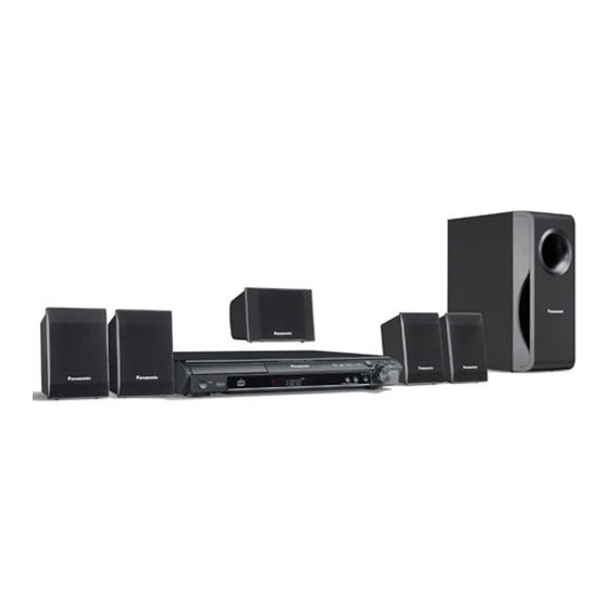
Main unit SA-PT160E/EB/EG
GENERAL
Power Supply:
Power Consumption:
Power Consumption in Standby Mode:
Dimensions (W×H×D):
Mass:
Operating Temperature Range:
Operating Humidity Range:
AMPLIFIER SECTION
RMS Output Power: Dolby Digital Mode
Front Ch:
55 W per channel (5 Ω), 1 kHz, 10% THD
Surround Ch:
55 W per channel (5 Ω), 1 kHz, 10% THD
Center Ch:
55 W per channel (5 Ω), 1 kHz, 10% THD
Subwoofer Ch:
55 W per channel (5 Ω), 100 Hz, 10 % THD
Total RMS Dolby Digital mode power:
DIN Output Power: Dolby Digital Mode
AC 230 V - 240 V, 50Hz (EB)
AC 230 V, 50Hz (E/EG)
105 W
approx. 1 W
430×60×342 mm
This unit 3 kg
0°C to +40°C
35% to 80% RH (no
condensation)
330 W
DVD Home Theater Sound System
SA-PT160E
SA-PT160EB
SA-PT160EG
Colour
(S).......................Silver Type (For E/EG only)
(K).......................Black Type (For E/EB/EG)
Front Ch:
Surround Ch:
Center Ch:
Subwoofer Ch:
Total DIN Dolby Digital mode power:
FM TUNER, TERMINALS SECTION
Preset Memory:
Frequency Modulation (FM)
Frequency range:87.50-108.00 MHz
Sensitivity:
S/N 26 dB:
Antenna terminals:
USB SECTION
USB Port:
USB standard:USB 2.0 full speed
Media file format support:
© 2008 Matsushita Electric Industrial Co., Ltd. All
rights
reserved.
distribution is a violation of law.
ORDER NO. MD0801017CE
25 W per channel (5 Ω), 1 kHz, 1% THD
25 W per channel (5 Ω), 1 kHz, 1% THD
25 W per channel (5 Ω), 1 kHz, 1% THD
25 W per channel (5 Ω), 100 Hz, 1 % THD
FM 30 stations
(50-kHz step)
1.8 µV (IHF)
1.4 µV
75 Ω (unbalanced)
MP3 (*.mp3)
WMA (*.wma)
JPEG (*.Jpg, *.JPEG)
Unauthorized
copying
150 W
and
Advertisement
Table of Contents

Related Manuals for Panasonic SA-PT160E


Summary of Contents for Panasonic SA-PT160E
- Page 1 SA-PT160EB SA-PT160EG Colour (S).......Silver Type (For E/EG only) (K).......Black Type (For E/EB/EG) Specifications Main unit SA-PT160E/EB/EG Front Ch: 25 W per channel (5 Ω), 1 kHz, 1% THD GENERAL Power Supply: AC 230 V - 240 V, 50Hz (EB) Surround Ch: 25 W per channel (5 Ω), 1 kHz, 1% THD...
- Page 2 Extremely long and narrow pictures may not be displayed. 2. Total harmonic distortion is measured by the digital spectrum analyzer. *4 MPEG4 data recorded with the Panasonic SD multi cameras or DVD video recorders. Solder: Conforming to SD VIDEO specifications (ASF standard)/ This model uses lead free solder (PbF).
- Page 3 SA-PT160E / SA-PT160EB / SA-PT160EG CONTENTS Page Page 1 Safety Precautions 1.2. Before Repair and Adjustment (Using SMPS Module 1.1. GENERAL GUIDELINES P.C.B.)
- Page 4 SA-PT160E / SA-PT160EB / SA-PT160EG 1.3. Protection Circuitry 11.2. Checking & Repairing Main P.C.B. 1.4. Safety Parts Information 11.3. Checking & Repairing SMPS Module P.C.B. 1.5. Caution for AC Cord 11.4. Checking & Repairing DVD Module P.C.B. 2 Prevention of Electro Static Discharge (ESD) to...
-
Page 5: Safety Precautions
SA-PT160E / SA-PT160EB / SA-PT160EG 1 Safety Precautions 1.1. GENERAL GUIDELINES 1. When servicing, observe the original lead dress. If a short circuit is found, replace all parts which have been overheated or damaged by the short circuit. 2. After servicing, see to it that all the protective devices such as insulation barriers, insulation papers shields are properly installed. -
Page 6: Safety Parts Information
SA-PT160E / SA-PT160EB / SA-PT160EG • • • • Sound stops during a performance. The function of this circuitry is to prevent circuitry damage if, for example, the positive and negative speaker connection wires are “shorted”, or if speaker systems with an impedance less than the indicated rated impedance of the amplifier are used. -
Page 7: Caution For Ac Cord
SA-PT160E / SA-PT160EB / SA-PT160EG 1.5. Caution for AC Cord (For United Kingdom) WARNING: DO NOT CONNECT EITHER WIRE TO THE EARTH TERMINAL WHICH IS MARKED WITH THE LETTER ( EB area code model only) E, BY THE EARTH SYMBOL OR COLOURED GREEN OR For your safety, please read the following text carefully. -
Page 8: Prevention Of Electrostatic Discharge (Esd) To Electrostatically Sensitive (Es) Devices
SA-PT160E / SA-PT160EB / SA-PT160EG 2 Prevention of Electro Static Discharge (ESD) to Electrostatically Sensitive (ES) Devices Some semiconductor (solid state) devices can be damaged easily by static electricity. Such components commonly are called Electrostatically Sensitive (ES) Devices. Examples of typical ES devices are integrated circuits and some field-effect transistors and semiconductor "chip"... -
Page 9: Precaution Of Laser Diode
SA-PT160E / SA-PT160EB / SA-PT160EG 3 Precaution of Laser Diode... -
Page 10: Service Caution Based On Legal Restrictions
SA-PT160E / SA-PT160EB / SA-PT160EG 4 About Lead Free Solder (PbF) 4.1. Service caution based on legal restrictions 4.1.1. General description about Lead Free Solder (PbF) The lead free solder has been used in the mounting process of all electrical components on the printed circuit boards used for this equipment in considering the globally environmental conservation. -
Page 11: Handling Precautions For Traverse Unit
SA-PT160E / SA-PT160EB / SA-PT160EG 5 Handling Precautions for Traverse Unit The laser diode in the optical pickup unit may break down due to static electricity of clothes or human body. Special care must be taken avoid caution to electrostatic breakdown when servicing and handling the laser diode. - Page 12 SA-PT160E / SA-PT160EB / SA-PT160EG...
- Page 13 SA-PT160E / SA-PT160EB / SA-PT160EG 6 Accessories FM indoor antenna Remote Control Antenna plug adaptor (For EB area only) AC cord (For E, EG areas) Speaker cable stickers AC cord (For EB area only)
-
Page 14: Operation Procedures
SA-PT160E / SA-PT160EB / SA-PT160EG 7 Operation Procedures 7.1. Remote Control Key Buttons Operations Television operations Adjust the television volume Switch the main unit on or off Select the source DVD: DVD/CD EXT-IN: AV *, AUX, USB Change the television’s video input mode Show the current disc’s playback... - Page 15 SA-PT160E / SA-PT160EB / SA-PT160EG 7.2. Main Unit Key Buttons Operations Standby/on switch [ /I] / TUNING Press to switch the unit from on to standby Skipping or slow-search play, mode or vice versa. In standby mode, the unit Select the radio stations is still consuming a small amount of power.
- Page 16 SA-PT160E / SA-PT160EB / SA-PT160EG 7.3. About DivX VOD Content (For E, EG areas only) DivX Video-on-Demand (VOD) content is encrypted for If you purchase DivX VOD content using a registration copyright protection. In order to play DivX VOD content on code different from this unit’s code, you will not be able...
-
Page 17: Usb Connection And Operation
SA-PT160E / SA-PT160EB / SA-PT160EG 7.4. USB Connection and Operation Optional Optional USB connection and operation USB connection and operation Adjust the volume of the main unit. The USB connectivity enables you to connect and play tracks or files f rom USB mass storage class devices. -
Page 18: Audio And Video Connections
SA-PT160E / SA-PT160EB / SA-PT160EG 7.5. Audio and Video Connections 7.5.1. Television with Scart Terminal 7.5.2. Audio Connection for Video Cassette Recorder or Television... - Page 19 SA-PT160E / SA-PT160EB / SA-PT160EG 7.5.3. Connection for Set Top Box...
-
Page 20: Disc Information
Closing the session will also work. MPEG4 data recorded with the Panasonic SD multi cameras or DVD video recorders [conforming to SD VIDEO specifications (ASF standard)/MPEG4 (Simple Profi le) video system/G.726 audio system]. - Page 21 You can play MPEG4 data [conforming to SD VIDEO speci c fi ations (ASF standard)/MPEG4 (Simple Pro le) video system/G.726 audio system] recorded with Panasonic SD multi cameras or DVD video rec orders with this unit. The recording date may differ from that of the actual date.
-
Page 22: Self-Diagnosis And Special Mode Setting
SA-PT160E / SA-PT160EB / SA-PT160EG 8 Self-Diagnosis and Special Mode Setting 8.1. Service Mode Summary Table The service modes can be activated by pressing various button combination on the main unit and remote control unit. Below is the summary for the various modes for checking:... - Page 23 SA-PT160E / SA-PT160EB / SA-PT160EG 8.2.1. Service Mode Table 1 Item Key Operation FL Display Mode Name Description Front Key Jitter check Jitter check. In STOP (no disc) mode, (Display 1) Jitter rate is measured and displayed. press [STOP] button on the...
- Page 24 SA-PT160E / SA-PT160EB / SA-PT160EG 8.2.2. Service Mode Table 2 Key Operation Item FL Display Mode Name Description Front Key (Display 1) DVD laser DVD laser drive current measurement. In STOP (no disc) mode, drive current DVD laser drive current is measured...
- Page 25 SA-PT160E / SA-PT160EB / SA-PT160EG 8.2.3. Service Mode Table 3 Item Key Operation FL Display Mode Name Description Front Key Micro-processor Micro-processor firmware version In STOP (no disc) (Display 1) firmware version display & EEPROM checksum display. mode, press [STOP] display &...
- Page 26 SA-PT160E / SA-PT160EB / SA-PT160EG Product Region TV Broadcasting Model Series Country Region Signal System Region Display Code OSD Menu Language System (Default) (Default) English, Spanish, Canadian P, PC, PX USA, Canada, PX NTSC NTSC (*A) French Japan NTSC NTSC (*A)
- Page 27 SA-PT160E / SA-PT160EB / SA-PT160EG 8.2.4. Service Mode Table 4 Item Key Operation FL Display Mode Name Description Front Key DVD Module P.C.B. firmware version In STOP (no disc) Module P.C.B. is displayed on the FL Display. mode, press [STOP]...
- Page 28 SA-PT160E / SA-PT160EB / SA-PT160EG 8.2.5. Service Mode Table 5 Item Key Operation FL Display Mode Name Description Front Key Timer 1 check Timer 1 check In STOP (no disc) (Display 1) Laser operation timer is measured mode, press [STOP] separately for DVD laser and CD laser.
- Page 29 SA-PT160E / SA-PT160EB / SA-PT160EG 8.2.6. Optical Pick-up Self-Diagnosis The optical pickup self-diagnosis function and tilt adjustment check function have been included in this unit. When repairing, use the following procedure for effective self-diagnosis and tilt adjustment. Be sure to use the self-diagnosis function before replacing the optical pickup when "NO DISC"...
-
Page 30: Dvd Self Diagnostic Function-Error Code
SA-PT160E / SA-PT160EB / SA-PT160EG 8.3. DVD Self Diagnostic Function-Error Code 8.3.1. Mechanism Error Code Table Error Diagnosis Contents Description of error Automatic FL Display Remarks Code H01 Tray loading error The tray opening and closing is Press [ STOP] on abnormal. - Page 31 SA-PT160E / SA-PT160EB / SA-PT160EG 8.3.2. DVD Module Error Code Table Error Diagnosis Contents Description of error Automatic FL Display Remarks Code U702 DVD/DVI I2C The communication error of I2C Press [ STOP] on communication error when connecting it with DVD/ main unit for next error.
-
Page 32: Power Amp
SA-PT160E / SA-PT160EB / SA-PT160EG 8.3.3. Power Supply Error Code Table Error Diagnosis Contents Description of error Automatic FL Display Remarks Code F61 The abnormalities In normal operation, when DCDET2 Press [ STOP] on in an output or power goes to "L" (Low) (Not during POWER main unit for next error. -
Page 33: Sales Demonstration Lock Function
SA-PT160E / SA-PT160EB / SA-PT160EG 8.3.5. USB Error Code Table Error Diagnosis Contents Description of error Automatic FL Display Remarks Code F650 USB device: Devices Devices other than the mass storage Press [ STOP] on other than mass class are connected. -
Page 34: Service Precautions
SA-PT160E / SA-PT160EB / SA-PT160EG 8.5. Service Precautions 8.5.1. Recovery after the DVD player is repaired • • • • When the FLASH ROM IC or DVD Module P.C.B. is replaced, carry out the recovery processing to optimize the drive. -
Page 35: Assembling And Disassembling
SA-PT160E / SA-PT160EB / SA-PT160EG 9 Assembling and Disassembling “ATTENTION SERVICER” Be careful when disassembling and servicing. Some chassis components may have sharp edges. Special Note: 1. This section describes the disassembly procedures for all the major printed circuit boards and main components. -
Page 36: Disassembly Flow Chart
SA-PT160E / SA-PT160EB / SA-PT160EG • • • • SMPS Module P.C.B. Replacement: 1. This model uses SMPS Module P.C.B. to provide the necessary supply voltages for the unit. 2. It is advisable to replace the SMPS Module P.C.B. once upon detecting of non-working conditions. Do not attempt to repair or replace it by components. -
Page 37: Main Components And P.c.b. Locations
SA-PT160E / SA-PT160EB / SA-PT160EG 9.2. Main Components and P.C.B. Locations... -
Page 38: Disassembly Of Top Cabinet
SA-PT160E / SA-PT160EB / SA-PT160EG 9.3. Disassembly of Top Cabinet Step 1 Remove 4 screws. Step 2 Remove 3 screws at the rear panel Step 3 Lift up and remove the top cabinet. Step 2 Insert the gear jig into the tray open/ close hole. -
Page 39: Disassembly Of Front Panel
SA-PT160E / SA-PT160EB / SA-PT160EG Note: You can return the tray by turning the gear jig clockwise. Step 6 Detach USB shield wire from the connector (CN8000) on USB P.C.B. 9.5. Disassembly of Front Panel Step 7 Remove the front panel. -
Page 40: Disassembly Of Usb P.c.b
SA-PT160E / SA-PT160EB / SA-PT160EG 9.8. Disassembly of USB P.C.B. • • • • Follow (Step 1) to (Step 3) of Item 9.3. Step 2 Remove 4 screws from Volume P.C.B.. • • • • Follow (Step 1) to (Step 4) of Item 9.4. -
Page 41: Disassembly Of Dvd Module
SA-PT160E / SA-PT160EB / SA-PT160EG 9.11. Disassembly of DVD Module P.C.B. • • • • Follow (Step 1) to (Step 3) of Item 9.3. • • • • Follow (Step 1) to (Step 4) of Item 9.4. 9.10. Disassembly of DVD •... -
Page 42: Disassembly Of Main P.c.b
SA-PT160E / SA-PT160EB / SA-PT160EG Step 3 Turn over DVD Module P.C.B. and detach FFC cable Step 1 Remove 1 screw from the bracket. from the connector (FP8531). Step 2 Remove the bracket. Step 4 Remove DVD Module P.C.B. • • • • Disassembly of Main P.C.B. -
Page 43: Replacement Of Regulator Ic (Ic2903)
SA-PT160E / SA-PT160EB / SA-PT160EG 9.14. Replacement of Digital Amp IC Note : For replacement of IC5200 & IC5300, repeat the (Step (IC5100/IC5200/IC5300) 1) to (Step 3). Refer to the diagrams of Main P.C.B. (Item 20.2) for the location of the parts. -
Page 44: Disassembly Of Smps Module
SA-PT160E / SA-PT160EB / SA-PT160EG Note : Refer to the diagrams of Main P.C.B. (Item 20.2) for the 9.17. Disassembly of Tuner Extent location of the part. P.C.B. 9.16. Disassembly of SMPS Module • • • • Follow (Step 1) to (Step 3) of Item 9.3. -
Page 45: Disassembly Procedure
SA-PT160E / SA-PT160EB / SA-PT160EG 10 Assembly and Disassembly of DVD Mechanism Unit 10.1. Disassembly Procedure Step 4 Remove the traverse unit. 10.1.1. Disassembly of Traverse Unit (with Middle Chassis) Step 1 Slide the lever (A) in the arrow direction (to the opposite side) till it stops. - Page 46 SA-PT160E / SA-PT160EB / SA-PT160EG (Assembly of the tray unit) Step 2 Raise the mecha chassis vertically. Step 1 Insert a part of the tray into the unit sliding over the Step 3 Slide the lever in the arrow direction till it stops and pull groove on the mecha chassis.
- Page 47 SA-PT160E / SA-PT160EB / SA-PT160EG Step 4 Remove the belt. Step 5 Unlock the tab and remove the pulley gear. 10.1.3. Disassembly of Loading Section Step 6 Remove the relay gear. Step 1 Spread the tabs at the both sides and push out the drive arm.
-
Page 48: Disassembly Of Traverse Unit
SA-PT160E / SA-PT160EB / SA-PT160EG Step 9 Pull the lever (B) at the bottom side in the direction of arrow and remove the change lever. 10.1.5. Disassembly of Traverse Unit Step 1 Spread the tabs to push in the pin in the direction of arrows. - Page 49 SA-PT160E / SA-PT160EB / SA-PT160EG Step 3 Remove the middle chassis. Step 4 Remove the traverse unit.
-
Page 50: Service Position
SA-PT160E / SA-PT160EB / SA-PT160EG DVD mechanism unit, USB Relay P.C.B., SMPS Module 11 Service Position P.C.B., Main P.C.B. & Tuner Extent P.C.B. according to diagram shown below. 11.1. Checking & Repairing Panel P.C.B. Step 1 Remove the top cabinet. - Page 51 SA-PT160E / SA-PT160EB / SA-PT160EG 11.3. Checking & Repairing SMPS Module P.C.B. • • • • Follow (Step 1) to (Step 13) of Item 11.2. Step 1 Turn over the SMPS Module P.C.B. according to the diagram shown below. 11.4. Checking & Repairing DVD Module P.C.B.
-
Page 52: Measurements And Adjustments
SA-PT160E / SA-PT160EB / SA-PT160EG 12 Measurements and Adjustments 12.1. Service Tools and Equipment Application Name Number Tilt adjustment DVD test disc DVDT-S20 [SPG] TORX screw driver (T6) Available on sales route. (T6) or RFKZ0185 [SPG] Others Grease RFKXPG641 [SPG]... -
Page 53: Optical Adjustment
SA-PT160E / SA-PT160EB / SA-PT160EG 12.4. Optical adjustment 12.4.1. Optical pickup tilt adjustment Measurement point Adjustment point Mode Disc Tangential adjustment screw T01 (inner periphery) play DVDT-S20 [SPG] Tilt adjustment screw T30 (center periphery) T43 (outer periphery) play Measuring equipment Adjustment value None (Main unit display for servicing is used.) - Page 54 SA-PT160E / SA-PT160EB / SA-PT160EG 13 Abbreviations INITIAL/LOGO ABBREVIATIONS ERROR TORQUE CONTROL ERROR TORQUE CONTROL INITIAL/LOGO ABBREVIATIONS REFERENCE A0~UP ADDRESS ENCSEL ENCODER SELECT ACLK AUDIO CLOCK ETMCLK EXTERNAL M CLOCK (81MHz/40.5MHz) AD0~UP ADDRESS BUS ETSCLK EXTERNAL S CLOCK (54MHz) ADATA...
- Page 55 SA-PT160E / SA-PT160EB / SA-PT160EG INITIAL/LOGO ABBREVIATIONS INITIAL/LOGO ABBREVIATIONS READ ENABLE VBLANK V BLANKING RFENV RF ENVELOPE COLLECTOR POWER SUPPLY RF PHASE DIFFERENCE OUTPUT VOLTAGE (CD-ROM) REGISTER SELECT VCDCONT VIDEO CD CONTROL (TRACKING RSEL RF POLARITY SELECT BALANCE) RESET DRAIN POWER SUPPLY VOLTAGE...
-
Page 56: Voltage And Waveform Chart
SA-PT160E / SA-PT160EB / SA-PT160EG 14 Voltage and Waveform Chart 14.1. DVD Module P.C.B. IC8001 Ref No. MODE CD PLAY IC8001 Ref No. MODE CD PLAY IC8001 Ref No. MODE CD PLAY Ref No. IC8001 MODE CD PLAY IC8001 Ref No. - Page 57 SA-PT160E / SA-PT160EB / SA-PT160EG IC8651 Ref No. MODE CD PLAY Ref No. IC8651 MODE CD PLAY IC8651 Ref No. MODE CD PLAY IC8691 IC8695 IC9003 Ref No. MODE CD PLAY IC9005 Ref No. MODE CD PLAY Q8321 Q8325 Q8331...
- Page 58 SA-PT160E / SA-PT160EB / SA-PT160EG 14.2. Main P.C.B. IC1101 Ref No. MODE CD PLAY STANDBY IC1101 IC1102 Ref No. MODE CD PLAY STANDBY IC2004 Ref No. MODE CD PLAY STANDBY Ref No. IC2018 MODE CD PLAY STANDBY IC2018 Ref No.
- Page 59 SA-PT160E / SA-PT160EB / SA-PT160EG 14.3. Panel P.C.B. IC6901 Ref No. MODE CD PLAY -24.4 -24.4 -24.4 -19.6 -19.8 STANDBY -24.4 -24.4 -24.4 -14.9 -19.6 -12.5 IC6901 Ref No. MODE CD PLAY -24.4 -24.4 -24.3 -17.2 -14.8 -24.4 -24.4 -24.4 14.8...
-
Page 60: Waveform Chart
SA-PT160E / SA-PT160EB / SA-PT160EG 14.5. Waveform Chart 14.5.1. Waveform 1 WF No. IC1101-8,21,24 (PLAY) WF No. IC1101-11 (PLAY) WF No. IC1101-13 (PLAY) 1.3Vp-p(20usec/div) 1.1Vp-p(20usec/div) 0.5Vp-p(20usec/div) 0.5Vp-p(20usec/div) WF No. IC1102-2 (PLAY) 0.8Vp-p(20usec/div) 0.9Vp-p(20usec/div) 2.1Vp-p(20usec/div) 2.1Vp-p(20usec/div) WF No. IC2018-13 (PLAY) WF No. IC2018-15 (PLAY) WF No. - Page 61 SA-PT160E / SA-PT160EB / SA-PT160EG 14.5.2. Waveform 2 WF No. IC8001-146 (PLAY) WF No. IC8251-12,15,17 (PLAY) WF No. IC8251-14 (PLAY) WF No. IC8421-16,19,20,21 22,26,27 (PLAY) 6.4Vp-p(2usec/div) 3.4Vp-p(200usec/div) 0.1Vp-p(200usec/div) 3.4Vp-p(200usec/div) WF No. IC8421-15 (PLAY) 2Vp-p(200usec/div)
-
Page 62: Illustration Of Ic's, Transistors And Diodes
SA-PT160E / SA-PT160EB / SA-PT160EG 15 Illustration of IC’s, Transistors and Diodes C1AB00001731 (6p) C0CBCBD00018 (8p) RFKWMHC0B320 C0HBB0000057 (44p) C3ABPG000145 (54p) C0DBZYE00002 (8p) C9ZB00000461 (32p) C1AB00002463 (100p) C0EBA0000029 (4p) C2CBYY000438 (100p) C0FBBK000050 (28p) MN2DS0018MP (216p) C0JBAB000908 (6p) No.1 No.1 C0GBG0000048... -
Page 63: Wiring Connection Diagram
SA-PT160E / SA-PT160EB / SA-PT160EG 16 Wiring Connection Diagram CP2010 PANEL P.C.B. TUNER EXTENT P.C.B. CN2002 Z6900 (SOLDER SIDE) (SOLDER SIDE) CN2010 CN6001 JK2002 SENSOR TO TUNER PACK UNIT JK1001 H6004 VR6800 VOLUME P.C.B. (SOLDER SIDE) VOLUME H2004 CN2001 JK5000... - Page 64 SA-PT160E / SA-PT160EB / SA-PT160EG...
-
Page 65: Block Diagram
SA-PT160E / SA-PT160EB / SA-PT160EG 17 Block Diagram 17.1. System Control FL6901 IC2018 C2CBYY000438 CN6001 CN2007 FL DISPLAY SYSTEM CONTROL FROM CN6001 CN2007 AMP & POWER IC6901 VREF C0HBB0000057 DISPLAY DRIVER S901 PLAY CS901 H2004 TRAY CLOSE MIC EN S902... - Page 66 SA-PT160E / SA-PT160EB / SA-PT160EG 17.2. DVD (Servo) : CD HEAD SIGNAL LINE : DVD RF SIGNAL LINE : TRACKING ERROR SIGNAL LINE : DVD HEAD SIGNAL LINE : MOTOR DRIVE SIGNAL LINE : FOCUS ERROR SIGNAL LINE IC8001 IC8251...
- Page 67 SA-PT160E / SA-PT160EB / SA-PT160EG 17.3. DVD (Audio) : DVD RF SIGNAL LINE : DVD AUDIO SIGNAL LINE : MAIN SIGNAL LINE : USB SIGNAL LINE IC8421 IC8001 C0FBBK000050 MN2DS0018MP AUDIO DAC DV5.0 LSI OPTICAL PICKUP UNIT FP8531 OUTPUT AMP AND...
- Page 68 SA-PT160E / SA-PT160EB / SA-PT160EG 17.4. DVD (Video) : DVD VIDEO SIGNAL LINE IC8001 MN2DS0018MP DV5.0 LSI Q8331 FP8101 CN2001 Y/PY/G DAC1 OUT BUFFER Q8335 CB/PB/B FP8101 CN2001 DAC2 OUT BUFFER Q8341 FP8101 CN2001 CR/PR/R DAC3 OUT BUFFER Q8321 FP8101...
- Page 69 SA-PT160E / SA-PT160EB / SA-PT160EG 17.5. Audio :MAIN SIGNAL LINE :FM SIGNAL LINE :AUX SIGNAL LINE :TV AUDIO SIGNAL LINE IC2102 C1AB00002463 AUDIO SIGNAL PROCESSOR JK1001 LINEOUT L RECOUTL LINEOUT R RECOUTR TV LCH INL3 TV RCH INR3 TONE Q1001...
-
Page 70: Amp & Power
Q5744 FAN DC OUT CN5704 MUTE H2001 MUTE FRONT MUTE FAN MOTOR FROM DRIVE FAN GND CN5704 SYSTEM CONTROL +26V +26V (VCC) STANDBY Q5745 STYB STANDBY CIRCUIT FAN DC +26V (VCC) SUPPLY Q5746 INVERTER SA-PT160E/EB/EG AMP & POWER BLOCK DIAGRAM... -
Page 71: Schematic Diagram Notes
SA-PT160E / SA-PT160EB / SA-PT160EG : DVD Audio signal line 18 Schematic Diagram Notes • • • • This schematic diagram may be modified at any time : DVD Video signal line with the development of new technology. : CD Head signal line... - Page 72 SA-PT160E / SA-PT160EB / SA-PT160EG...
-
Page 73: Schematic Diagram
SA-PT160E / SA-PT160EB / SA-PT160EG 19 Schematic Diagram 19.1. DVD Module Circuit SCHEMATIC DIAGRAM - 1 : CD HEAD SIGNAL LINE : DVD RF SIGNAL LINE : DVD AUDIO SIGNAL LINE : FOCUS ERROR SIGNAL LINE : USB SIGNAL LINE... - Page 74 SA-PT160E / SA-PT160EB / SA-PT160EG SCHEMATIC DIAGRAM - 2 : CD HEAD SIGNAL LINE : DVD RF SIGNAL LINE : DVD AUDIO SIGNAL LINE : FOCUS ERROR SIGNAL LINE : USB SIGNAL LINE DVD MODULE CIRCUIT : +B SIGNAL LINE...
- Page 75 SA-PT160E / SA-PT160EB / SA-PT160EG SCHEMATIC DIAGRAM - 3 : CD HEAD SIGNAL LINE : DVD RF SIGNAL LINE : DVD AUDIO SIGNAL LINE : FOCUS ERROR SIGNAL LINE : USB SIGNAL LINE DVD MODULE CIRCUIT : +B SIGNAL LINE...
- Page 76 SA-PT160E / SA-PT160EB / SA-PT160EG SCHEMATIC DIAGRAM - 4 : CD HEAD SIGNAL LINE : DVD RF SIGNAL LINE : DVD AUDIO SIGNAL LINE : FOCUS ERROR SIGNAL LINE : USB SIGNAL LINE DVD MODULE CIRCUIT : +B SIGNAL LINE...
- Page 77 SA-PT160E / SA-PT160EB / SA-PT160EG 19.2. Main Circuit SCHEMATIC DIAGRAM - 5 MAIN CIRCUIT :+B SIGNAL LINE :-B SIGNAL LINE :MAIN SIGNAL LINE :DVD VIDEO SIGNAL LINE :FM SIGNAL LINE :AUX SIGNAL LINE :TV AUDIO SIGNAL LINE SW+5V R2411 C2023...
- Page 78 SA-PT160E / SA-PT160EB / SA-PT160EG SCHEMATIC DIAGRAM - 6 MAIN CIRCUIT :+B SIGNAL LINE :-B SIGNAL LINE :MAIN SIGNAL LINE :DVD VIDEO SIGNAL LINE :FM SIGNAL LINE :AUX SIGNAL LINE :TV AUDIO SIGNAL LINE R2427 CHASSIS VREF W4055 CN2007 SW+5V...
- Page 79 SA-PT160E / SA-PT160EB / SA-PT160EG SCHEMATIC DIAGRAM - 7 MAIN CIRCUIT :+B SIGNAL LINE :-B SIGNAL LINE :MAIN SIGNAL LINE :DVD VIDEO SIGNAL LINE :FM SIGNAL LINE :AUX SIGNAL LINE :TV AUDIO SIGNAL LINE Q1007 B1ADCE000012 W4090 Q1007 TO MAIN...
- Page 80 SA-PT160E / SA-PT160EB / SA-PT160EG SCHEMATIC DIAGRAM - 8 MAIN CIRCUIT :+B SIGNAL LINE :-B SIGNAL LINE :MAIN SIGNAL LINE :DVD VIDEO SIGNAL LINE :FM SIGNAL LINE :AUX SIGNAL LINE :TV AUDIO SIGNAL LINE TO MAIN IC5100 L5101 SECTION (2/4)
- Page 81 REMOTE CONTROL SENSOR FLGND (FL+) FL1 MAIN CIRCUIT (CN2007) W6513 IN SCHEMATIC S6800 C6918 (FL-) FL2 KEY1 10V47 DIAGRAM - 6 KEY1 POWER W6511 DGND STBLED R6905 1.5K STBLED D6900 VREF B3AAA0000803 VREF R6934 SA-PT160E/EB/EG TUNER EXTENT / PANEL / VOLUME CIRCUIT...
- Page 82 CS901 TRAY CW M+9V GND1 VREF+ MAIN CIRCUIT TRAY CCW (H2004) IN SCHEMATIC TRY CLOSE TRY OPEN DIAGRAM - 6 S901 PLAY C984 25V10 S902 OPEN LOADING MOTOR (REF NO. 316) SA-PT160E/EB/EG USB RELAY / USB / TRAY LOADING CIRCUIT...
-
Page 83: Printed Circuit Board
SA-PT160E / SA-PT160EB / SA-PT160EG 20 Printed Circuit Board 20.1. DVD Module P.C.B. DVD MODULE P.C.B (REPX0562A) FP8531 (TO OPTICAL PICKUP UNIT) C8258 C8256 R8263 CKE24 C8262 C8530 CKE6 LB8530 R8261 CKE11 CKE12 CKE19 C8257 IC8251 CKE14 CKE22 C8254 CKE2... - Page 84 SA-PT160E / SA-PT160EB / SA-PT160EG 20.2. Main P.C.B. MAIN P.C.B. (REPX0581G...E, REPX0581B...EB, REPX0581A...EG) W2258 W2282 L2801 Q2805 CN2002 R2807 W4017 W2032 C2169 R2160 C2162 R2161 W2268 W2267 W2033 C2026 D1002 L1001 R1004 JK2002 Q1002 Q1003 W4100 Q1001 C2264 Q1004 C1201...
- Page 85 SA-PT160E / SA-PT160EB / SA-PT160EG 20.3. Panel, Volume & Tuner Extent P.C.B. PANEL P.C.B. (REPX0581G...E) (REPX0581B...EB) (REPX0581A...EG) W6513 FL6901 W6012 C6917 W6002 W6011 R6916 R6919 W6001 C6916 R6914 W6004 S6800 C6905 W6010 C6918 C6906 (POWER) W6003 R6939 L6903 W6006 IC6901...
- Page 86 SA-PT160E / SA-PT160EB / SA-PT160EG 20.4. USB, USB Relay & Tray Loading P.C.B. USB RELAY P.C.B. (REPX0581G...E) TRAY LOADING P.C.B. (REP4238A) (REPX0581B...EB) (REPX0581A...EG) IC904 S902 CS901 (OPEN SW) CN8002 0534A-2 0534A-2 REF NO.316 S901 (LOADING MOTOR) (PLAY SW) K8001 PbF 2462A-1...
-
Page 87: Basic Troubleshooting Guide For Traverse Unit (Dvd Module P.c.b)
SA-PT160E / SA-PT160EB / SA-PT160EG 21 Basic Troubleshooting Guide 21.1. Basic Troubleshooting Guide for Traverse Unit (DVD Module P.C.B) Problems Checking Points Checking Components 1) Distorted picture or a) Check SDRAM address, IC8051 abnormal sound is head data bus, CLK and other... - Page 88 SA-PT160E / SA-PT160EB / SA-PT160EG 21.2. Basic Troubleshooting Guide for SMPS/MAIN/PANEL Problems Checking Points Checking Components 1) No power supply to unit a) Check AC cord connection (open/short) b) Check fuse F1 on SMPS Module P.C.B. c) Check supply voltage to H2002 Pin 1, 4, 8, 9, 11 Main P.C.B.
- Page 89 SA-PT160E / SA-PT160EB / SA-PT160EG 22 Overall Block Diagram for PT160 22.1. SC-PT160 Simplified Block...
-
Page 90: Terminal Function Of Ics
SA-PT160E / SA-PT160EB / SA-PT160EG 23 Terminal Function of ICs 23.1. IC2018 (C2CBYY000438): Terminal Name Function System Control IC 55 NC No Connection 56 NC No Connection Terminal Name Function 57 NC No Connection 58 NC No Connection TRAY_CLOSE LOADING MECHA CLOSE SW (L: SW... -
Page 91: Exploded Views
SA-PT160E / SA-PT160EB / SA-PT160EG 24 Exploded Views 24.1. Cabinet Parts Location... - Page 92 SA-PT160E / SA-PT160EB / SA-PT160EG...
- Page 93 SA-PT160E / SA-PT160EB / SA-PT160EG 24.2. Packaging...
- Page 94 SA-PT160E / SA-PT160EB / SA-PT160EG...
-
Page 95: Replacement Parts List
SA-PT160E / SA-PT160EB / SA-PT160EG 25 Replacement Parts List Notes: *Important safety notice: Components identified by mark have special characteristics important for safety purpose. Furthermore, special parts which have purposes of fire-retardant (resistors), high-quality sound (capacitors), low-noise (resistors), etc. are used. -
Page 96: Component Parts List
SA-PT160E / SA-PT160EB / SA-PT160EG 25.1. Component Parts List Ref. Part No. Part Name & Description Remarks N0AZ6GE00005 SMPS MODULE Ref. Part No. Part Name & Description Remarks (RTL) CABINET AND CHASSIS J3CBBC000001 TUNER PACK TRAVERSE DECK L6FAJCCH0007 FAN MOTOR... - Page 97 SA-PT160E / SA-PT160EB / SA-PT160EG Ref. Part No. Part Name & Description Remarks Ref. Part No. Part Name & Description Remarks REPX0581A USB P.C.B Q8335 2SB1218ARL TRANSISTOR (RTL) Q8341 2SB1218ARL TRANSISTOR Q8551 2SD1819A0L TRANSISTOR PCB7 REPX0581G USB RELAY P.C.B Q8552...
- Page 98 SA-PT160E / SA-PT160EB / SA-PT160EG Ref. Part No. Part Name & Description Remarks Ref. Part No. Part Name & Description Remarks CN8000 K1KA05BA0061 5P CONNECTOR CN8001 K1FY104B0011 USB CONNECTOR HOLDERS CN8002 K1KA05BA0061 5P CONNECTOR CN8003 K1MY05BA0130 5P CONNECTOR H2001 K1YF04000001...
- Page 99 SA-PT160E / SA-PT160EB / SA-PT160EG Ref. Part No. Part Name & Description Remarks Ref. Part No. Part Name & Description Remarks W4039 D0GDR00JA017 0 1/10W K2CQ2CA00007 AC CORD E/EG- W4040 D0GBR00JA008 0 1/16W W4042 D0GBR00JA008 0 1/16W K2CT3CA00004 AC CORD...
- Page 100 SA-PT160E / SA-PT160EB / SA-PT160EG Ref. Part No. Part Name & Description Remarks Ref. Part No. Part Name & Description Remarks R2029 D0GB221JA007 220 1/10W R2115 D0GB103JA007 10K 1/10W R2030 D0GB221JA007 220 1/10W R2160 D0GB563JA008 56K 1/16W R2031 D0GB221JA007 220 1/10W...
- Page 101 SA-PT160E / SA-PT160EB / SA-PT160EG Ref. Part No. Part Name & Description Remarks Ref. Part No. Part Name & Description Remarks R2901 D0GB103JA007 10K 1/10W R5311 D0GB103JA007 10K 1/10W R2907 D0GB392JA008 3.9K 1/16W R5312 D0GB102JA008 1K 1/16W R2908 D0GB221JA007 220 1/10W...
- Page 102 SA-PT160E / SA-PT160EB / SA-PT160EG Ref. Part No. Part Name & Description Remarks Ref. Part No. Part Name & Description Remarks R8337 ERJ2RHD102X 1K 1/16W C984 ECA1EAK100XE 10 25V R8341 ERJ3RBD201V 200 1/16W C1001 F2A1C101A180 100uF 16V R8342 D0GA330JA023 33 1/16W...
- Page 103 SA-PT160E / SA-PT160EB / SA-PT160EG Ref. Part No. Part Name & Description Remarks Ref. Part No. Part Name & Description Remarks C2265 F1H1H102A219 1000pF 50V C2984 F1H1H104A013 0.1uF 50V C2272 F1H1H101A230 100pF 50V C2985 F1H1H103A219 0.01uF 50V C2283 F1H1A105A025 1uF 10V...
- Page 104 SA-PT160E / SA-PT160EB / SA-PT160EG Ref. Part No. Part Name & Description Remarks Ref. Part No. Part Name & Description Remarks C6913 ECA1HM3R3B 3.3uF 50V C8401 F1G1H150A565 15pF 50V C6916 F1H1H101A720 100pF 50V C8402 F1G1H150A565 15pF 50V C6917 F1H1H101A720 100pF 50V...