
Related Manuals for GE SVI II AP


Summary of Contents for GE SVI II AP
- Page 1 GE Oil & Gas Masoneilan* SVI* II AP Digital Positioner Quick Start Guide (Rev. N) GE Data Classification: Public...
- Page 2 The information contained in this manual, in whole or part, shall not be transcribed or copied without GE’s written permission. In no case does this manual guarantee the merchantability of the positioner or the software or its adaptability to a specific client needs.
-
Page 3: Table Of Contents
Mounting the SVI II AP on Reciprocating Valves ................. 25 Checking the Magnet ..........................29 Installing the SVI II AP for Double- Acting Operation ..............30 Connecting the Tubing and Air Supply ..................... 33 Connecting the Air Supply ........................34 Wiring the SVI II AP ............................. - Page 4 Checking the Air Supply ..........................42 Checking the Electronic Module Connections ................42 Operational Checkout ..........................44 Connecting to the Current Source ..................... 44 Powering Up the SVI II AP ........................44 Configuration ..............................46 Configuration with Pushbuttons ......................46 Viewing Status Messages ........................48 VIEW DATA Settings ..........................48...
- Page 5 Updated the Load Limits section. Updated ES-699 to Rev. AA. Updated Disclaimer statement. Added information on position retransmit switches. Removed Remote Positioner Installation. © 2015 General Electric Company. All rights reserved Masoneilan SVI II AP Digital Positioner Quick Start Guide...
- Page 6 Page Left Blank Intentionally...
-
Page 7: Safety Information
Indicates a potentially hazardous situation, which if CAUTION not avoided could result in instrument or property damage, or data loss. Indicates important facts and conditions. NOTE Masoneilan SVI II AP Digital Positioner Quick Start Guide =| 7 © 2015 General Electric Company. All rights reserved... -
Page 8: Svi Ii Ap Product Safety
SVI II AP Product Safety The SVI II AP digital valve positioner is intended for use with industrial compressed air or, natural gas systems only. NOTE See “Hazardous Location Installation” on page 66 for natural gas safety information. Ensure that an adequate pressure relief provision is installed when the application of system supply pressure could cause peripheral equipment to malfunction. - Page 9 Under certain operating conditions the SVI II AP High Flow unit can produce noise levels greater than 85 dBA. Perform proper site...
- Page 10 This page intentionally left blank.
-
Page 11: Installation And Set Up
2. Installation and Set Up Introduction The SVI II AP provides for reliable operations of control valves with utmost simplicity in setup and commissioning. It is uniquely equipped with a non-contact travel sensor allowing for accurate positioning and maintenance free operations. The pneumatic train of the SVI II AP is a dual-stage amplification system with stainless steel wetted parts for durability. - Page 12 Pneumatic Relay Figure 2 SVI II AP Components Manifold Cover (I/P Module) Relay Electronics Module SVI II AP Cover Figure 3 SVI II AP High Flow Components © 2015 General Electric Company. All rights reserved 12 | =GE Oil & Gas...
-
Page 13: Using The Quick Start Guide
Using the Quick Start Guide The SVI II AP Quick Start Guide is intended to help an experienced field engineer install, setup, and calibrate an SVI II AP in an efficient manner. This document provides basic installation and setup instructions and is not intended to replace the in-depth information contained in the SVI II AP In- struction Manual. -
Page 14: Single Acting Positioner
Two pressure gauges, output on top, supply port on bottom, are located on the front of the pneu- matic block. The supply and output connections for the SVI II AP High Flow (Figure 5 on page 15), located on bottom and leftside of the pneumatic block, are tapped 1⁄2" NPT. -
Page 15: Double Acting Positioner
Supply Output Figure 5 SVI II AP High Flow Air Ports on Single Acting Positioner Double Acting Positioner I) to the inlet port of the actuator and Output 2, labeled ( II) to Connect Output 1, labeled( the opposing actuator port (see Figure 6). -
Page 16: Pushbuttons And Local Display
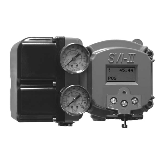
The pushbuttons do not support diagnostics functions. The SVI II AP has two operational modes: Normal Operating Mode and Manual Mode and two set- up modes, Configuration and Calibration. The SVI II AP also has two modes for handling of faults and power-up: Reset and Failsafe. - Page 17 When used to increase a displayed value holding this button down causes the value to increase at a faster rate. NOTE When an exclamation point (!) appears in the SVI II AP display window, it indicates that there is instrument status available. (Forward)
- Page 18 See ValVue documentation for more details. The SVI II AP offers several levels of accessibility. It may be desirable, after initial setup, to lock the pushbuttons so that the SVI II AP parameters cannot be inadvertently changed by the buttons.
- Page 19 Process Variable Remote Position Sensor Input 4- 20 mA Input Signal Display Figure 8 Connections to Electronics Module (via Terminal Board) Masoneilan SVI II AP Digital Positioner Quick Start Guide =| 19 © 2015 General Electric Company. All rights reserved...
-
Page 20: Valvue* Software
CD-ROM drive. ValVue Full Trial Version The SVI II AP comes with a copy of ValVue Trial Version software that can be used for sixty days without a license. After the 60-day trial period, ValVue must be registered. ValVue, full version, provides advanced diagnostic, maintenance capabilities and basic calibration and configura- tion for the SVI II AP. -
Page 21: Mounting The Svi Ii Ap
Mounting the SVI II AP This guide provides installation instructions for mounting an SVI II AP on both rotary and recipro- cating actuated valves. The mounting process can be broken down into the following: Attach the mounting bracket to the actuator. -
Page 22: Mounting The Svi Ii Ap On Rotary Valves
Mounting the SVI II AP on Rotary Valves This section describes the procedure for mounting the SVI II AP on rotary control valves that have less than 60° rotation, such as a Masoneilan Camflex II or a Masoneilan Varimax . Figure 9 shows a side view of a Camflex actuator and the SVI II AP actuator mounting brackets. - Page 23 Secure the magnet holder with two M6 set screws. 8. Slide the V-Seal over the magnet holder. 9. Secure the SVI II AP onto the mounting bracket using four M6 x 20 mm socket head cap screws. 10. Ensure no interference exists with the position sensor protrusion.
-
Page 24: Travel Sensor Alignment
Travel Sensor Alignment Table 3 shows the general guidelines for travel sensor alignment. Review the table prior to in- stalling the SVI II AP on a rotary valve actuator for proper alignment of the magnet. Table 3: Travel Sensor Alignment... -
Page 25: Mounting The Svi Ii Ap On Reciprocating Valves
To remove the SVI II AP Controller from a rotary valve perform Steps 1 - 9 on page 22 in reverse. Mounting the SVI II AP on Reciprocating Valves The process of mounting the SVI II AP on a reciprocating valve consists of mounting the unit on the actuator that is attached to the valve. - Page 26 27. Ensure that the travel pointer located on the coupling is correctly positioned. 6. Attach the right hand threaded rod end to the SVI II AP lever using a 1⁄4 - 20 x 1" cap screw and nut as shown. The lever hole position to be used depends upon the specific valve stroke.
- Page 27 10. Thread the turnbuckle onto the left hand threaded rod end (Figure 12). 11. Adjust the turnbuckle until the hole in the SVI II AP lever is aligned with the indicating hole in the bracket. Tighten both turnbuckle lock nuts. Refer to Figure 11.
- Page 28 To remove the SVI II AP Controller from a reciprocating valve perform Steps 1 - 12 on page 25 in the reverse order.
-
Page 29: Checking The Magnet
Checking the Magnet There are two methods of checking the SVI II AP magnet: Perform a visual inspection Use ValVue to check the magnet Performing a Visual Inspection To perform a visual inspection refer to Table 3 on page 24 and ensure that the magnet is correct- ly oriented for the actuator/valve configuration. -
Page 30: Installing The Svi Ii Ap For Double- Acting Operation
Installing the SVI II AP for Double- Acting Operation This section explains how to mount the SVI II AP for the 84/85/86 kit for double-acting valve po- sitioner configurations. To mount the kit: 1. Set valve to the closed position. - Page 31 For bottom: hex nut regular 1/4-20 and hex screw 1/4-20 UNC x 22.2 [.88] LG. Figure 16 Bracket Configuration Strokes .5 - 2.50” and 3-6” Masoneilan SVI II AP Digital Positioner Quick Start Guide =| 31 © 2015 General Electric Company. All rights reserved...
- Page 32 7. Mount the SVI-II with M6-1 screws. 8. Cycle the valve open to close verifying proper components movement and that rod-ends move free and clear from other components. © 2015 General Electric Company. All rights reserved 32 | =GE Oil & Gas...
-
Page 33: Connecting The Tubing And Air Supply
Connecting the Tubing and Air Supply The last step in hardware installation for the SVI II AP is to connect the air supply to the positioner. This section describes the process for connecting the tubing and air supply to a single and double acting positioner. -
Page 34: Connecting The Air Supply
Wiring the SVI II AP In order for the SVI II AP to communicate the positioner data the SVI II AP positioner must be physically connected to a HART® communication. The procedure below outlines wiring the SVI II AP. -
Page 35: Connecting To The Control Loop
Compliance voltage at the SVI II AP must be 9 V at the maximum current of 20 mA. Signal to the SVI II AP must be a regulated current in the range 3.2 to 22 mA. ® Controller output circuit must be unaffected by the HART tones which are in the frequency range between 1200 and 2200 Hz. -
Page 36: Svi Ii Ap Setups
SVI II AP. If the SVI II AP is located in a haz- ardous area with Intrinsically Safe protection a barrier is not required for a flameproof installa- tion. -
Page 37: Compliance Voltage In Single Drop Current Mode
2. Connect a milliampmeter in series with the current signal. 3. Verify that source can supply 20 mA to SVI II AP input. If 20 mA is not attainable, troubleshoot the source and set up. NOTE Improperly or inadequately grounded installations can cause noise or instability in the control loop. - Page 38 SVI II AP Supply Single Channel Zener Barrier Barrier Resistance 220 Ohms HART® compliant control system output card HART® Modem ValVue DPI620 Figure 20 Intrinsically Safe Installation © 2015 General Electric Company. All rights reserved 38 | =GE Oil & Gas...
-
Page 39: Check Out, Configuration And Calibration
Calibration Overview This section provides the calibration procedures to ensure proper valve positioning. Operational checkout, configuration and calibration procedures are described using an SVI II AP that has a display with pushbuttons. Perform all procedures in this section before putting NOTE the SVI II AP into operation. -
Page 40: Inspecting Actuator, Linkages, Or Rotary Adapter
Inspecting Actuator, Linkages, or Rotary Adapter Verify that the mounting has not been damaged in shipment for a pre-mounted SVI II AP, physi- cally inspect the actuator, linkage. Record the following information for the configuration check- out: 1. Valve Air to Open (ATO) or Air to Close (ATC) 2. - Page 41 When the valve is at mid-travel the value should be between –1000 and +1000 for a greater than 60° rotation rotary valve. Masoneilan SVI II AP Digital Positioner Quick Start Guide =| 41 © 2015 General Electric Company. All rights reserved...
-
Page 42: Checking The Air Supply
Hazardous Area unless the power is disconnected. All connections to electronic module in the SVI II AP are made through the terminal board. The SVI II AP terminal board has a terminal block with cage clamp connectors. Confirm that all appli- cable connections to the electronics module connectors are correct. - Page 43 Figure 23 Connections to Electronics Module (via Terminal Board) NOTE When an SVI II AP is turned on it is advisable to apply the air supply before applying the electrical input signal. Masoneilan SVI II AP Digital Positioner Quick Start Guide =| 43...
-
Page 44: Operational Checkout
Connect to a DC mA current source then check and configure with the local display and push- buttons, if so equipped. The following section describes configuration and calibration with the optional local display and pushbuttons. If the SVI II AP is not equipped with local display use Val- Vue Lite and a PC with a HART modem or a HART Handheld Communicator. - Page 45 To power up the SVI II AP: 1. Loosen the four (4) cover screws and remove the cover of the SVI II AP. Connect the +⁄- terminals to the current source + to + and - to -. See Figure 23 on page 43.
-
Page 46: Configuration
Configuration Use the procedures that follow to: calibrate, tune, view configuration data and status messages for the SVI II AP. Observe all warnings as the valve moves during these procedures. WARNING These procedures can cause the valve to move. Before proceeding be sure the valve is isolated from the process. - Page 47 Because calibration depends on certain configuration options you must perform Configuration before you perform Calibration when installing the SVI II AP for the first time. If a change is made in the Air-to-Open / Air-to-Close configuration option or if you move the SVI II AP to a different valve or make any change to the valve position linkage, you must run the find STOPS calibration again.
-
Page 48: Viewing Status Messages
Viewing Status Messages To view SVI II AP status messages: 1. Press + and * to select VIEW ERR 2. Observe any internal errors. For example, there should be a RESET status caused by powering up. If the positioner was powered without air a Position Error or POSERR can appear. -
Page 49: Calibration
To calibrate the SVI II AP: 1. Observe the display following power-up. The SVI II AP powers up in the previously active mode either MANUAL or NORMAL (operating) mode: In NORMAL mode, the display alternates between POS and SIGNAL. - Page 50 SVI II AP. If a change is made in the Air-To-Open/Air-To-Close configuration option or if you move the SVI II AP to a different valve or make any change to the valve position linkage, you must run the find STOPS calibration again.
- Page 51 2. When autoTUNE is complete, TUNE appears. 3. Press + repeatedly until SETUP appears. CALIB appears. 4. Press * to return to SETUP menu; Masoneilan SVI II AP Digital Positioner Quick Start Guide =| 51 © 2015 General Electric Company. All rights reserved...
- Page 52 View ERR CLR ERR Setup Data MAN POS <value> * - + Manual Calib Config Config Calib Menu Menu Figure 26 NORMAL Operation and MANUAL Menu Structures © 2015 General Electric Company. All rights reserved 52 | =GE Oil & Gas...
-
Page 53: Check-Out With A Hart® Handheld Communicator
Check-out with a HART Handheld Communicator ® If the SVI II AP is not equipped with optional push buttons and local display the checkout and con- figuration is performed using the standard HART communications interface. ® onnect the HART handheld communicator to the SVI II AP as shown in Figure 27. Refer to the ®... - Page 54 (Position Error, for example) or go to the troubleshooting guide. 14. Correct the problem (Is the air supply on?), and then go to clear status until Clear Fault codes Completed appears. 15. Press OK. © 2015 General Electric Company. All rights reserved 54 | =GE Oil & Gas...
-
Page 55: Maintenance
4. Maintenance SVI II AP Maintenance The SVI II AP was designed based on a modular concept. All components are interchangeable allowing for easy, quick component swapping. The only maintenance procedures recommended for the SVI II AP are: Remove and install the cover... -
Page 56: Display Cover Removal And Installation
Display Cover Removal and Installation The cover with display (shown in Figure 28) is an option for the SVI II AP. If you have an SVI II AP with a solid cover and would like to upgrade to a display cover, follow the instructions below for removal and installation. - Page 57 The replacement display cover is shipped with a lanyard to prevent the cable (that connects from the display to the terminal board) from breaking. The lanyard must be inserted under the screw in the lower left corner that attaches the terminal board to the SVI II AP housing. To install the cover: 1.
- Page 58 This page intentionally left blank.
-
Page 59: Specifications And References
A. Specifications and References Physical and Operational Specifications This section provides the physical and operational specifications for the SVI II AP. Specifications are subject to change without notice. Table 8: Environmental Specifications Operating Temperature Limits -58° F to 185° F (-50° C to 85° C) Storage Temperature Limits -58°... - Page 60 Proportional gain: 0 to 5, displayed as 0 to 5000 Integral time: 0 to 100 seconds - displayed as 0 to 1000 (1/ SVI II AP performs automatic determination of the opti- 10s) mal valve position control parameters. In addition to P, I,...
- Page 61 300 series stainless steel Magnet Holder Corrosion Protected Anodized Aluminum 6061 T6 Pole Ring 416 stainless steel Levers 300 Series stainless steel Masoneilan SVI II AP Digital Positioner Quick Start Guide =| 61 © 2015 General Electric Company. All rights reserved...
- Page 62 0%, and put the process control system in manual, for smooth recovery from air supply failure. Loss of Input Signal Actuator Output fails to atmosphere Output Pressure 0-150 psi (10.3 bar) max © 2015 General Electric Company. All rights reserved 62 | =GE Oil & Gas...
- Page 63 Loss of Input Signal Output drops to low pressure. Output Pressure 0-150 psi (10 bar) max Masoneilan SVI II AP Digital Positioner Quick Start Guide =| 63 © 2015 General Electric Company. All rights reserved...
- Page 64 Always set control set point to 0%, and put the process control system in man- ual, for smooth recovery from air supply failure. Loss of Input Signal Output 1 fails to atmosphere Output 2 fails to supply pressure. © 2015 General Electric Company. All rights reserved 64 | =GE Oil & Gas...
- Page 65 1. ATEX/FM/CSA/Intrinsic Safety & Exprf 4. ATEX (IS, NI) Approved Configuration Codes SVI2 AP- Figure 29 SVI II AP Model Numbering Masoneilan SVI II AP Digital Positioner Quick Start Guide =| 65 © 2015 General Electric Company. All rights reserved...
-
Page 66: Hazardous Location Installation
The following pages provide the agency approved installation procedure for hazardous loca- tions. NOTE The installation procedure is accurate at time of print. For further hazardous installation information please consult the factory. © 2015 General Electric Company. All rights reserved 66 | =GE Oil & Gas... - Page 67 Wiring must be rated for at least 5ºC above the highest expected ambient temperature. ES-699 Rev AA Page 1 of 16 Masoneilan SVI II AP Digital Positioner Quick Start Guide =| 67 © 2015 General Electric Company. All rights reserved...
- Page 68 5. Verify that the markings on the label are consistent with the application. 6. Verify that the air supply pressure cannot exceed the marking on the respective label. ES-699 Rev AA Page 2 of 16 © 2015 General Electric Company. All rights reserved 68 | =GE Oil & Gas...
- Page 69 (see Section 6). Natural gas Use of a pressurized gas which is ignitable in the presence of air (for example natural gas) is not allowed as the SVI II AP supply pressure in a flameproof (protection type “d”) installation. Bolting...
- Page 70 T5 : Ta = -40°C to +55°C T4 : Ta = -40°C to +83°C Category II 1 (Zone 0) ES-699 Rev AA Page 4 of 16 © 2015 General Electric Company. All rights reserved 70 | =GE Oil & Gas...
- Page 71 10% aluminum, care must be taken during installation to avoid impacts or friction that could create an ignition source. ES-699 Rev AA Page 5 of 16 Masoneilan SVI II AP Digital Positioner Quick Start Guide =| 71 © 2015 General Electric Company. All rights reserved...
- Page 72 XP – CL I; DIV 1; GP A, B, C, D {Explosionproof} DIP – CL II/III; DIV 1; GP E, F, G {Dust Ignitionproof} ES-699 Rev AA Page 6 of 16 © 2015 General Electric Company. All rights reserved 72 | =GE Oil & Gas...
- Page 73 Temp: -40°C to +85°C 6.3.2 Voltage: 30 Volts 6.3.3 Pressure: 150 psig (1.03MPa) 6.3.4 Current: 4-20mA ES-699 Rev AA Page 7 of 16 Masoneilan SVI II AP Digital Positioner Quick Start Guide =| 73 © 2015 General Electric Company. All rights reserved...
- Page 74 HAS BEEN MARKED, IT CAN NOT BE CHANGED Model Code: SVI2-abcdefgh (see section 3 above for explanation) Serial Number: SN-nnyywwnnnn ES-699 Rev AA Page 8 of 16 © 2015 General Electric Company. All rights reserved 74 | =GE Oil & Gas...
- Page 75 (ATEX) {Explosion Protected Mark} {CE Conformity Marking, QAN Notified Body Number} ZELM {Certifying Agency} ES-699 Rev AA Page 9 of 16 Masoneilan SVI II AP Digital Positioner Quick Start Guide =| 75 © 2015 General Electric Company. All rights reserved...
- Page 76 HAS BEEN MARKED, IT CAN NOT BE CHANGED Model Code: SVI2-1bcdefg4 (see section 3 above for explanation) Serial Number: SN-nnyywwnnnn ES-699 Rev AA Page 10 of 16 © 2015 General Electric Company. All rights reserved 76 | =GE Oil & Gas...
- Page 77 Solendoid Control System DI to Control System SEE NOTE 9.6 LOAD SEE NOTE 9.6 ES-699 Rev AA Page 11 of 16 Masoneilan SVI II AP Digital Positioner Quick Start Guide =| 77 © 2015 General Electric Company. All rights reserved...
- Page 78 Vmax = 30 Vdc; Imax = 125 mA; Ci = 8 nF; Li = 1 uH max = 900 mW. ES-699 Rev AA Page 12 of 16 © 2015 General Electric Company. All rights reserved 78 | =GE Oil & Gas...
- Page 79 Uo/Voc = 6.5 Volts Io/Isc = 72 mA Ca = 1.25 uF La = 2 mH Connect only to passive (Un-powered) switch. ES-699 Rev AA Page 13 of 16 Masoneilan SVI II AP Digital Positioner Quick Start Guide =| 79 © 2015 General Electric Company. All rights reserved...
- Page 80 IMPAIR SUITABILITY FOR USE IN A HAZARDOUS LOCATION. Only qualified service personnel are permitted to make repairs On the SVI II AP, replacement of the pneumatic cover, electronics module, the pneumatic relay, the I/P, and the main cover (with or without display) are the only field repairs permitted.
- Page 81 FM 3810: 2005 Housing ANSI/NEMA 250: 2003 Housing ANSI/IEC 60529: 2004 Class – Division Classification ES-699 Rev AA Page 15 of 16 Masoneilan SVI II AP Digital Positioner Quick Start Guide =| 81 © 2015 General Electric Company. All rights reserved...
- Page 82 Industrial Products Degrees of protection provided by enclosures (IP CSA C22.2 NO 60529-05 Code) 12 HISTORY Copyright 2014. This document and all information herein is the property of GE Oil and Gas. Description Date Initial Release 16 Aug 05 Revised model code, min XP temp 27 SEP 05 was –20°C;...
-
Page 83: Spare Parts
Spare Parts Masoneilan SVI II AP Digital Positioner Quick Start Guide =| 83 © 2015 General Electric Company. All rights reserved... - Page 84 © 2015 General Electric Company. All rights reserved 84 | =GE Oil & Gas...
- Page 85 Masoneilan SVI II AP Digital Positioner Quick Start Guide =| 85 © 2015 General Electric Company. All rights reserved...
- Page 86 Relay Spare Part Kit, Standard Construction, High Flow, Single Acting SVI II AP-2 720014541-999-0000 Item Part Number Description Quantity 720017771-265-0000 SCR HEX SHCS M4 X 0.7 X 60 MICROSPHERES 593 PATCH 971886015-681-0000 O-RING ID 9.19 [0.362] WIDTH 2.62 [0.103] REF...
-
Page 87: Optional Switch Load Limits
Appendix B. Optional Switch Load Limits General Configuration Notes The SVI II AP supports two identical contact outputs, SW #1 and SW #2 (Digital Output switches), that can be logically linked to status bits. The Digital Output switch terminals are solid state con- tacts. - Page 88 Load is designed to ensure that voltage across the switch is < 1 V. LOAD External SVI II AP Switch Voltage Output: 1 V Source with switch ON Figure 30 Simplified Switch Installation Drawing: Correct Configuration © 2015 General Electric Company. All rights reserved 88 | =GE Oil & Gas...
-
Page 89: Checking Switch Operation
4. Select Command 142 Read Switches from the pulldown list and click Send Cmd. The information field below populates with the configured switch states. Ensure that the switch just reconfigured has changed state. Masoneilan SVI II AP Digital Positioner Quick Start Guide =| 89 © 2015 General Electric Company. All rights reserved... - Page 90 This page intentionally left blank.
- Page 92 DIRECT SALES OFFICE LOCATIONS AUSTRALIA ITALY SOUTH AFRICA Brisbane Phone:++39-081-7892-111 Phone:++27-11-452-1550 Phone:++61-7-3001-4319 Fax:++++39-081-7892-208 Fax:++++27-11-452-6542 Fax:++++61-7-3001-4399 Perth JAPAN SOUTH & CENTRAL Phone:++61-8-6595-7018 Tokyo AMERICA AND THE CARIBBEAN Fax:++++61-8-6595-7299 Phone:++81-03-6871-9008 Phone:++55-12-2134-1201 Fax:++++81-03-6890-4620 Fax:++++55-12-2134-1238 Melbourne KOREA SPAIN Phone:++61-3-8807-6002 Phone:++82-2-2274-0748 Phone:++34-93-652-6430 Fax:++++61-3-8807-6577 Fax:++++82-2-2274-0794 Fax:++++34-93-652-6444 BELGIUM MALAYSIA UNITED ARAB EMIRATES...