Table of Contents
Advertisement
Quick Links
GE Consumer & Industrial
Multilin
Ia = 100
Ic = 100
GE Multilin
215 Anderson Avenue, Markham, Ontario
Canada L6E 1B3
Tel: (905) 294-6222 Fax: (905) 201-2098
Internet: http://www.GEmultilin.com
*1665-0003-CK*
PQM POWER QUALITY METER – INSTRUCTION MANUAL
Courtesy of NationalSwitchgear.com
Ib = 102
AMPS
g
PQM
Power Quality Meter
STATUS
COMMUNICATE
RELAYS
ALARM
TX1
ALARM
PROGRAM
RX1
AUX1
SIMULATION
TX2
AUX2
SELF TEST
RX2
AUX3
PQM
Power Quality Meter™
INSTRUCTION MANUAL
Software Revision: 3.6x
Manual P/N: 1665-0003-CJ
Manual Order Code: GEK-106296E
Copyright © 2006 GE Multilin
ACTUAL
SETPOINT
MESSAGE
VALUE
STORE
RESET
823787A4.CDR
ISO9001:2000
GE Multilin's Quality Management
System is registered to ISO9001:2000
QMI # 005094
UL # A3775
1–1
Advertisement
Table of Contents

Related Manuals for GE Multilin PQM


Summary of Contents for GE Multilin PQM
- Page 1 GE Consumer & Industrial Multilin Power Quality Meter™ INSTRUCTION MANUAL Software Revision: 3.6x Manual P/N: 1665-0003-CJ Manual Order Code: GEK-106296E Copyright © 2006 GE Multilin ACTUAL STORE Ia = 100 Ib = 102 SETPOINT RESET Ic = 100 AMPS MESSAGE...
- Page 2 The contents of this manual are the property of GE Multilin Inc. This documentation is furnished on license and may not be reproduced in whole or in part without the permission of GE Multilin. The content of this manual is for informational use only and is subject to change without notice.
- Page 3 Courtesy of NationalSwitchgear.com...
- Page 4 Courtesy of NationalSwitchgear.com...
-
Page 5: Table Of Contents
TABLE OF CONTENTS Table of Contents 1: OVERVIEW INTRODUCTION .........................1-1 ........................1-1 ESCRIPTION ......................1-2 EATURE IGHLIGHTS ........................1-3 PPLICATIONS STANDARD FEATURES .....................1-5 ..........................1-5 ETERING ......................1-6 UTURE XPANSION ......................1-6 PTIONAL EATURES PQM S ................1-11 ISTA ETUP OFTWARE ........................ - Page 6 TABLE OF CONTENTS DEFAULT MESSAGES ......................3-9 ........................3-9 ESCRIPTION ..................3-9 DDING A EFAULT ESSAGE ..................3-9 ELETING A EFAULT ESSAGE 4: PROGRAMMING INTRODUCTION .........................4-1 ....................4-1 ETPOINT NTRY ETHODS S1 PQM SETUP ........................4-3 ........................4-3 ESCRIPTION ........................4-3 REFERENCES .......................
- Page 7 TABLE OF CONTENTS 5: MONITORING ACTUAL VALUES VIEWING ....................5-1 ........................5-1 ESCRIPTION A1 METERING ........................5-3 ..........................5-3 URRENT ..........................5-5 OLTAGE ..........................5-7 HASORS ..........................5-9 OWER ..........................5-14 NERGY ..........................5-16 EMAND .......................... 5-17 REQUENCY ........................5-18 ULSE OUNTER ........................
- Page 8 TABLE OF CONTENTS 7: MODBUS OVERVIEW ...........................7-1 COMMUNICATIONS ......................7-1 ODBUS ROTOCOL ....................... 7-1 LECTRICAL NTERFACE & D .................... 7-2 ORMAT ....................... 7-2 ACKET ORMAT ........................ 7-3 RROR HECKING CRC-16 A ......................7-3 LGORITHM ..........................7-4 IMING MODBUS FUNCTIONS ......................7-5 PQM S ................
- Page 9 TABLE OF CONTENTS APPENDIX: APPLICATION EVENT RECORDER ......................A-1 NOTES INTERFACING USING HYPERTERMINAL ...............A-7 PHASORS IMPLEMENTATION ..................A-10 TRIGGERED TRACE MEMORY ..................A-12 PULSE OUTPUT APPLICATION ..................A-13 DATA LOGGER IMPLEMENTATION ................A-15 READING LONG INTEGERS FROM MEMORY MAP .............A-20 PULSE INPUT APPLICATION ...................A-22 PULSE TOTALIZER APPLICATION ...................A-24 PQM POWER QUALITY METER –...
- Page 10 TABLE OF CONTENTS TOC–VI PQM POWER QUALITY METER – INSTRUCTION MANUAL Courtesy of NationalSwitchgear.com...
-
Page 11: Description
1.1.1 Description The GE Multilin PQM Power Quality Meter is an ideal choice for continuous monitoring of a single or three-phase system. It provides metering for current, voltage, real power, reactive power, apparent power, energy use, cost of power, power factor, and frequency. -
Page 12: Feature Highlights
INTRODUCTION CHAPTER 1: OVERVIEW 1.1.2 Feature • Monitor: A, V, VA, W, var, kWh, kvarh, kVAh, PF, Hz Highlights • Demand metering: W, var, A, VA • Setpoints for alarm or control from most measured values, including: unbalance, frequency, power factor, voltage, and current •... -
Page 13: Applications
CHAPTER 1: OVERVIEW INTRODUCTION ANALOG INPUT Accept 4-20mA analog inputs for transducer interface. ANALOG OUTPUTS 4 isolated 0-1mA or 4-20 mA outputs replace 8 transducers. Programmable including: A, V, W, var, VA, Wh varh, PF, Hz SWITCH INPUTS Programmable for relay activation, counters, logic, demand synchronization, setpoint access, alarm position 4 OUTPUT RELAYS... - Page 14 INTRODUCTION CHAPTER 1: OVERVIEW 3 PHASE 3/4 WIRE BUS 0-600V DIRECT >600V CT/VTs PQM RELAY AC/DC CONTROL POWER 4 SWITCH INPUTS FOR CONTROL MAIN COM 1 SCADA ALARM OUTPUT INSTRUMENTATION CONTROL RELAYS COM 2 ELECTRICAL MAINTENANCE 4-20mA RS232 TRANSDUCER PORT OUTPUTS 823768A2.CDR FIGURE 1–3: Single Line Diagram...
-
Page 15: Standard Features
CHAPTER 1: OVERVIEW STANDARD FEATURES Standard Features 1.2.1 Metering True RMS monitoring of I , voltage/current unbalance, power factor, line frequency, watts, vars, VA, Wh, varh, VAh, and demand readings for A, W, vars, and VA. Maximum and minimum values of measured quantities are recorded and are date and time stamped. -
Page 16: Future Expansion
Flash memory is used to store firmware within the PQM. This allows future product Expansion upgrades to be loaded via the serial port. Product update Transfer new firmware from GE Power to the PQM Management Products CD 823774A6.CDR FIGURE 1–4: Downloading Product Enhancements via the Serial Port PQM units can initially be used as standalone meters. - Page 17 CHAPTER 1: OVERVIEW STANDARD FEATURES d) Control Option An additional three dry-contact form “C” output relays and four dry-contact switch inputs are provided. These additional relays can be combined with setpoints and inputs/outputs for control applications. Possibilities include: • undercurrent alarm warnings for pump protection •...
- Page 18 STANDARD FEATURES CHAPTER 1: OVERVIEW FIGURE 1–7: Harmonic Spectrum Voltage and current waveforms can be captured and displayed on a PC with EnerVista PQM Setup or third party software. Distorted peaks or notches from SCR switching provide clues for taking corrective action. FIGURE 1–8: Captured Waveform 1–8 PQM POWER QUALITY METER –...
- Page 19 CHAPTER 1: OVERVIEW STANDARD FEATURES Alarms, setpoint triggers, and input and output events can be stored in a 40-event record and time/date stamped by the internal clock. This is useful for diagnosing problems and system activity. The event record is available through serial communication. Minimum and maximum values are also continuously updated and time/date stamped.
- Page 20 STANDARD FEATURES CHAPTER 1: OVERVIEW The power analysis option also provides a Trace Memory feature. This feature can be used to record specified parameters based on the user defined triggers. FIGURE 1–10: Trace Memory Triggers FIGURE 1–11: Trace Memory Capture 1–10 PQM POWER QUALITY METER –...
-
Page 21: Enervista Pqm Setup Software
CHAPTER 1: OVERVIEW STANDARD FEATURES 1.2.4 EnerVista PQM All data continuously gathered by the PQM can be transferred to a third party software Setup program for display, control, or analysis through the communications interface. The Software EnerVista PQM Setup software makes this data immediately useful and assists in programming the PQM. -
Page 22: Order Codes
STANDARD FEATURES CHAPTER 1: OVERVIEW 1.2.5 Order Codes The order code for all options is: PQM-T20-C-A Table 1–1: Order Codes * * * Basic Unit with display, all current/voltage/power Basic Unit measurements, 1 RS485 communication port, 1 RS232 communication port Transducer 4 isolated analog outputs, 0-20 mA and 4-20 mA Option... -
Page 23: Specifications
CHAPTER 1: OVERVIEW SPECIFICATIONS Specifications 1.3.1 CURRENT INPUTS CONVERSION: true rms, 64 samples/cycle Specifications CT INPUT: 1 A and 5 A secondary BURDEN: 0.2 VA OVERLOAD: 20 × CT for 1 sec. 100 × CT for 0.2 sec. RANGE: 1 to 150% of CT primary FULL SCALE 150% of CT primary FREQUENCY:... - Page 24 SPECIFICATIONS CHAPTER 1: OVERVIEW ANALOG OUTPUTS OUTPUT 0-1 mA 4-20 mA (T1 Option) (T20 Option) MAX LOAD 2400 Ω 600 Ω MAX OUTPUT 1.1 mA 21 mA ACCURACY: ±1% of full scale reading ISOLATION: ±36 V isolated, active source ANALOG INPUT RANGE: 4 to 20 mA ACCURACY:...
- Page 25 CHAPTER 1: OVERVIEW SPECIFICATIONS Table 2: Measured Values PARAMETER ACCURACY RANGE VOLTAGE ±0.2% of full scale 20 to 100% of VT CURRENT ±0.2% of full scale 1 to 150% of CT V UNBALANCE ±1% of full scale 0 to 100% I UNBALANCE ±1% of full scale 0 to 100%...
- Page 26 SPECIFICATIONS CHAPTER 1: OVERVIEW OVERVOLTAGE MONITORING PICKUP: 1.01 to 1.25 in steps of 0.01 × VT DROPOUT: 97% of pickup TIME DELAY: 0.5 to 600.0 in steps of 0.5 sec. Any 1 / Any 2 / All 3 (programmable) must be ≥ pickup to PHASES: operate ACCURACY:...
- Page 27 CHAPTER 1: OVERVIEW SPECIFICATIONS PULSE INPUT MAX INPUTS: MIN PULSE WIDTH: 150 ms MIN OFF TIME: 200 ms COMMUNICATIONS COM1/COM2 TYPE: RS485 2-wire, half duplex, isolated COM3 TYPE: RS232 9-pin BAUD RATE: 1200 to 19200 ® PROTOCOLS: Modbus RTU; DNP 3.0 FUNCTIONS: Read/write setpoints Read actual values...
- Page 28 SPECIFICATIONS CHAPTER 1: OVERVIEW PACKAGING SHIPPING BOX:......8½" × 6" × 6" (L×H×D) 21.5cm × 15.2cm × 15.2 cm (L×H×D) SHIP WEIGHT: ......5 lbs/2.3 kg CERTIFICATION ISO: ........... Manufactured under an ISO9001 registered program UL:............. E83849 UL listed for the USA and Canada CE:.............
-
Page 29: Mounting
GE Consumer & Industrial Multilin PQM Power Quality Meter ACTUAL STORE Ia = 100 Ib = 102 SETPOINT RESET Ic = 100 AMPS MESSAGE Power Quality Meter STATUS COMMUNICATE RELAYS Chapter 2: Installation ALARM ALARM VALUE PROGRAM AUX1 SIMULATION AUX2... -
Page 30: Product Identification
PHYSICAL CHAPTER 2: INSTALLATION FIGURE 2–1: Physical Dimensions 2.1.2 Product Product attributes vary according to the configuration and options selected on the Identification customer order. Before applying power to the PQM, examine the label on the back and ensure the correct options are installed. 2–2 PQM POWER QUALITY METER –... -
Page 31: Revision History
TAG#: An optional identification number specified by the customer. MOD#: Used if unique features have been installed for special customer orders. This number should be available when contacting GE Multilin for technical support. VERSION: An internal GE Multilin number that should be available when contacting us for technical support. - Page 32 PHYSICAL CHAPTER 2: INSTALLATION Table 2–1: Revision History Table INSTRUCTION MAIN PROGRAM MANUAL P/N VERSION 1665-0003-C5 1.20 1665-0003-C6 1.21, 1.22 1665-0003-C7 2.00 1665-0003-C8 2.01 1665-0003-C9 2.02 1665-0003-CA 3.00 1665-0003-CB 3.01 1665-0003-CC 3.10 1665-0003-CD 3.13 1665-0003-CE 3.2x, 3.3x 1665-0003-CF 3.4x 1665-0003-CG 3.5x 1665-0003-CH 3.6x...
-
Page 33: Electrical
CHAPTER 2: INSTALLATION ELECTRICAL Electrical 2.2.1 External Signal wiring is to Terminals 21 to 51. These terminals accommodate wires sizes up to 12 Connections gauge. Please note that the maximum torque that can be applied to terminals 21 to 51 is 0.5 Nm (or 4.4 in ·lb.). - Page 34 ELECTRICAL CHAPTER 2: INSTALLATION Table 2–2: PQM External Connections VT / CONTROL POWER CT ROW SIGNAL UPPER ROW Alarm relay NC Alarm relay COM Alarm relay NO Comm 1 COM Comm 1 – Comm 1 + Comm 2 COM Comm 2 – Comm 2 + FIGURE 2–3: Rear Terminals 2–6...
- Page 35 CHAPTER 2: INSTALLATION ELECTRICAL This wiring diagram shows the typical 4-wire wye connection which will cover any voltage S2 SYSTEM SETUP \ CURRENT/VOLTAGE CONFIGURATION \ VT range. Select the WIRING: 4 WIRE WYE (3 VTs) setpoint. FIGURE 2–4: Wiring Diagram 4-wire Wye (3 Vts) PQM POWER QUALITY METER –...
- Page 36 ELECTRICAL CHAPTER 2: INSTALLATION The 2½ element 4 wire wye connection can be used for situations where cost or size restrictions limit the number of VTs to two. With this connection, Phase V voltage is S2 SYSTEM SETUP \ CURRENT/ calculated using the two existing voltages.
- Page 37 CHAPTER 2: INSTALLATION ELECTRICAL FIGURE 2–5: Wiring Diagram 4-wire Wye (2 Vts) Four-wire systems with voltages 347 V L-N or less can be directly connected to the PQM S2 SYSTEM SETUP \ CURRENT/VOLTAGE CONFIGURATION \ VT without VTs. Select the WIRING: 4 WIRE WYE DIRECT setpoint.
- Page 38 ELECTRICAL CHAPTER 2: INSTALLATION The PQM voltage inputs should be directly connected using HRC fuses rated at 2 A to ensure adequate interrupting capacity. FIGURE 2–6: Wiring Diagram 4-wire Wye Direct (No Vts) 2–10 PQM POWER QUALITY METER – INSTRUCTION MANUAL Courtesy of NationalSwitchgear.com...
- Page 39 CHAPTER 2: INSTALLATION ELECTRICAL This diagram shows the typical 3-wire delta connection which will cover any voltage range. S2 SYSTEM SETUP \ CURRENT/VOLTAGE CONFIGURATION \ VT WIRING: Select the setpoint. WIRE DELTA (2 VTs) FIGURE 2–7: Wiring Diagram 3-wire Delta (2 Vts) PQM POWER QUALITY METER –...
- Page 40 ELECTRICAL CHAPTER 2: INSTALLATION Three-wire systems with voltages 600 V (L-L) or less can be directly connected to the PQM S2 SYSTEM SETUP \ CURRENT/VOLTAGE CONFIGURATION \ VT without VTs. Select the WIRING: 3 WIRE DIRECT setpoint. The PQM voltage inputs should be directly connected using HRC fuses rated at 2 amps to ensure adequate interrupting capacity.
- Page 41 CHAPTER 2: INSTALLATION ELECTRICAL For a single-phase connection, connect current and voltage to the phase A inputs only. All S2 SYSTEM SETUP \ CURRENT/VOLTAGE other inputs are ignored. Select the CONFIGURATION \ VT WIRING: SINGLE PHASE setpoint. FIGURE 2–9: Single Phase Connection The figure below shows two methods for connecting CTs to the PQM for a 3-wire system.
- Page 42 ELECTRICAL CHAPTER 2: INSTALLATION measured by connecting the commons from phase A and C to the phase B input on the PQM. This causes the phase A and phase C current to flow through the PQM’s phase B CT in the opposite direction, producing a current equal to the actual phase B current.
-
Page 43: Control Power
CHAPTER 2: INSTALLATION ELECTRICAL 2.2.2 Control Power The control power supplied to the PQM must match the installed power supply. If the applied voltage does not match, damage to the unit may occur. Check the product identification to verify the control voltage matches the CAUTION intended application. -
Page 44: Output Relays
ELECTRICAL CHAPTER 2: INSTALLATION 2.2.5 Output Relays The basic PQM comes equipped with one output relay; the control option supplies three additional output relays. The PQM output relays have form C contacts (normally open (NO), normally closed (NC), and common (COM)). The contact rating for each relay is 5 A resistive and 5 A inductive at 250 V AC. - Page 45 CHAPTER 2: INSTALLATION ELECTRICAL Each switch input can be programmed with a 20-character user defined name and can be selected to accept a normally open or normally closed switch. A list of various functions that are assignable to switches is shown below, followed by a description of each function. ALARM RELAY NEW DEMAND PERIOD SETPOINT ACCESS...
-
Page 46: Analog Outputs (Optional)
ELECTRICAL CHAPTER 2: INSTALLATION not active, the parameter assigned in setpoint S2 SYSTEM SETUP \ ANALOG INPUT \ ANALOG INPUT MAIN is used. If a relay is assigned in S2 SYSTEM SETUP \ ANALOG INPUT \ ANALOG IN MAIN/ALT SELECT RELAY , that relay energizes when the switch is active and de-energizes when the switch is not active, thus providing the ability to feed in analog inputs from two separate sources as shown in the figure below. -
Page 47: Analog Input (Optional)
CHAPTER 2: INSTALLATION ELECTRICAL The outputs for these transducers can be selected from any of the measured parameters in the PQM. The choice of output is selected in the S2 SYSTEM SETUP \ ANALOG OUTPUT 1-4 setpoints group. See Section 4.3.2: Analog Outputs on page –24 for a list of available parameters. - Page 48 The master should be centrally located and can be used to view actual values and setpoints from each PQM called the slave device. Other GE Multilin relays or devices using the Modbus RTU protocol can be connected to the communication link.
-
Page 49: Rs232 Front Panel Port
CHAPTER 2: INSTALLATION ELECTRICAL GE Power Management Protection Relay SR Series GE Power Management Protection Relay RS485.CDR FIGURE 2–14: RS485 Communication Wiring 2.2.10 RS232 Front A 9-pin RS232C serial port provided on the front panel allows the user to program the PQM Panel Port with a personal computer. -
Page 50: Dielectric Strength Testing
ELECTRICAL CHAPTER 2: INSTALLATION The RS232 port is only available with the display version. See Section 1.2.5: Order Codes on page –12 for further details. NOTE 2.2.11 Dielectric It may be required to test the complete switchgear for dielectric strength with the PQM Strength installed. -
Page 51: Front Panel & Display
GE Consumer & Industrial Multilin PQM Power Quality Meter ACTUAL STORE Ia = 100 Ib = 102 SETPOINT RESET Ic = 100 AMPS MESSAGE Power Quality Meter STATUS COMMUNICATE RELAYS Chapter 3: Operation ALARM ALARM VALUE PROGRAM AUX1 SIMULATION AUX2... -
Page 52: Display
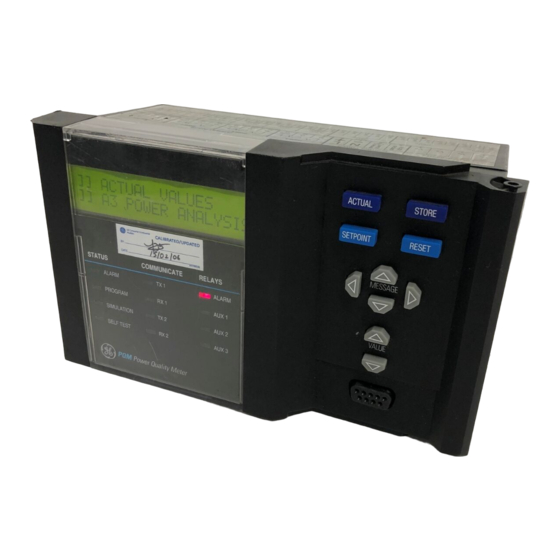
FRONT PANEL & DISPLAY CHAPTER 3: OPERATION ACTUAL STORE Ia = 100 Ib = 102 SETPOINT RESET Ic = 100 AMPS MESSAGE Power Quality Meter STATUS COMMUNICATE RELAYS ALARM ALARM VALUE PROGRAM AUX1 SIMULATION AUX2 SELF TEST AUX3 FIGURE 3–1: Front Panel 3.1.2 Display All messages are displayed in English on the 40-character liquid crystal display. -
Page 53: Status Indicators
CHAPTER 3: OPERATION STATUS INDICATORS Status Indicators 3.2.1 Description The status indicators provide a quick indication of the overall status of the PQM. These indicators illuminate if an alarm is present, if setpoint access is enabled, if the PQM is in simulation mode, or if there is a problem with the PQM itself. -
Page 54: Relays
STATUS INDICATORS CHAPTER 3: OPERATION • TX2: The PQM is transmitting information via the COM2 RS485 communications port when lit. • RX2: The PQM is receiving information via the COM2 RS485 communications port when lit. 3.2.4 Relays The status of the output relays is displayed with these indicators. •... -
Page 55: Keypad
CHAPTER 3: OPERATION KEYPAD Keypad 3.3.1 Description FIGURE 3–4: Front Panel Keys 3.3.2 Setpoint Key Setpoints are arranged into groups of related messages called setpoint pages. Each time key is pressed, the display advances to the first message of the next page of SETPOINT setpoints. -
Page 56: Reset Key
KEYPAD CHAPTER 3: OPERATION 3.3.5 Reset Key key is used to clear the latched alarm and/or auxiliary conditions. Upon RESET pressing the key, the PQM will perform the appropriate action based on the condition present as shown in the table below. Table 3–1: Reset Key Actions CONDITION PRESENT MESSAGE DISPLAYED... -
Page 57: Value Keys
CHAPTER 3: OPERATION KEYPAD To select messages within a subgroup press . To back out of the subgroup, MESSAGE press to access the previous message or to go to the next MESSAGE MESSAGE subgroup. SETPOINT SETPOINT ]] SETPOINTS ]] SETPOINTS ]] S1 PQM SETUP ]] S2 SYSTEM SETUP MESSAGE ▲... -
Page 58: Setpoint Access Security
KEYPAD CHAPTER 3: OPERATION The messages are organized into logical subgroups within each Setpoints and Actual Values page as shown below. Press the key when displaying a subgroup to access messages MESSAGE MESSAGE within that subgroup. Otherwise select the keys to MESSAGE MESSAGE display the next subgroup. -
Page 59: Default Messages
CHAPTER 3: OPERATION DEFAULT MESSAGES Default Messages 3.4.1 Description Up to 10 default messages can be selected to display sequentially when the PQM is left unattended. If no keys are pressed for the default message time in the S1 PQM SETUP \ PREFERENCES \ DEFAULT MESSAGE TIME setpoint, then the currently displayed message will automatically be overwritten by the first default message. - Page 60 DEFAULT MESSAGES CHAPTER 3: OPERATION V A L I D D E F A U L T STORE STORE M E S S A G E RESET THREE PHASE REAL TO DELETE THIS DEFAULT MESSAGE POWER = 1000 kW MESSAGE PRESS STORE R E M O V E D D I S P L A Y E D F O R 3 S E C O N D S D I S P L A Y E D F O R 3 S E C O N D S...
-
Page 61: Introduction
To facilitate this process, the EnerVista PQM Setup programming software is available from GE Multilin. With this software installed on a portable computer, all setpoints can be downloaded to the PQM. Refer to Chapter 6 for additional details. - Page 62 INTRODUCTION CHAPTER 4: PROGRAMMING SETPOINT SETPOINT SETPOINT SETPOINT SETPOINT ]] SETPOINTS ]] SETPOINTS ]] SETPOINTS ]] SETPOINTS ]] SETPOINTS ]] S1 PQM SETUP ]] S2 SYSTEM SETUP ]] S3 OUTPUT RELAYS ]] S4 ALARMS/CONTROL ]] S5 TESTING MESSAGE ▼ ▼ ▼ ▼ MESSAGE ▼...
-
Page 63: S1 Pqm Setup
CHAPTER 4: PROGRAMMING S1 PQM SETUP S1 PQM Setup 4.2.1 Description Settings to configure the PQM itself are entered on this page. This includes user preferences, the RS485 and RS232 communication ports, loading of factory defaults, and user programmable messages. 4.2.2 Preferences SETPOINT... -
Page 64: Setpoint Access
S1 PQM SETUP CHAPTER 4: PROGRAMMING DEFAULT MESSAGE BRIGHTNESS setpoint is only applicable for PQMs with older hardware revisions that include a vacuum fluorescent display (VFD), not a liquid crystal display (LCD). NOTE • DISPLAY FILTER CONSTANT: Display filtering may be required in applications where large fluctuations in currents and/or voltages are normally present. - Page 65 CHAPTER 4: PROGRAMMING S1 PQM SETUP To enable setpoint access, follow the steps outlined in the diagram below: STORE STORE SETPOINT ACCESS: ENTER SETPOINT SETPOINT ACCESS ON ENABLE ACCESS CODE: FOR: 5 min. C O R R E C T C O D E I N C O R R E C T C O D E...
- Page 66 S1 PQM SETUP CHAPTER 4: PROGRAMMING If the control option is installed and one of the switches is assigned to SETPOINT ACCESS , the setpoint access switch and the software setpoint access will act as a logic AND. That is, both conditions must be satisfied before setpoint access will be enabled.
-
Page 67: Rs485/Rs232 S P
CHAPTER 4: PROGRAMMING S1 PQM SETUP 4.2.4 RS485/RS232 Serial Ports SETPOINT ]] SETPOINTS ]] SETPOINTS ]] S1 PQM SETUP ]] S2 SYSTEM SETUP ] PREFERENCES ] SETPOINT ACCESS MESSAGE ] COM1 RS485 MODBUS COMMUNICATION Range: 1 to 255; Step 1 ] SERIAL PORT ADDRESS: Range: 1200, 2400, 4800,... - Page 68 S1 PQM SETUP CHAPTER 4: PROGRAMMING 4.2.5 DNP 3.0 Configuration SETPOINT ]] SETPOINTS ]] SETPOINTS ]] S1 PQM SETUP ]] S2 SYSTEM SETUP ] PREFERENCES ] SETPOINT ACCESS ] COM1 RS485 ] SERIAL PORT ] COM2 RS485 ] SERIAL PORT ] FRONT PANEL RS232 ] SERIAL PORT MESSAGE...
-
Page 69: Clock
CHAPTER 4: PROGRAMMING S1 PQM SETUP 4.2.6 Clock SETPOINT ]] SETPOINTS ]] SETPOINTS ]] S1 PQM SETUP ]] S2 SYSTEM SETUP ] PREFERENCES MESSAGE MESSAGE ] FRONT PANEL RS232 ] SERIAL PORT ] DNP 3.0 ] CONFIGURATION MESSAGE MESSAGE MESSAGE ] CLOCK SET TIME hh:mm:ss 12:00:00 am... -
Page 70: Calculation Parameters
S1 PQM SETUP CHAPTER 4: PROGRAMMING 4.2.7 Calculation The PQM can be programmed to calculate metering quantities and demand by various Parameters methods. SETPOINT ]] SETPOINTS ]] SETPOINTS ]] S1 PQM SETUP ]] S2 SYSTEM SETUP ] PREFERENCES MESSAGE MESSAGE ] CLOCK MESSAGE Range: ENABLE, DISABLE... - Page 71 CHAPTER 4: PROGRAMMING S1 PQM SETUP • DEMAND: The PQM calculates demand using the three methods described in the table below. METHOD DESCRIPTION This selection emulates the action of an analog peak-recording thermal demand meter. The PQM measures the average quantity (RMS current, real power, reactive power, or apparent power) on each phase every minute and assumes the circuit quantity remains at this value until updated by the next measurement.
-
Page 72: Clear Data
S1 PQM SETUP CHAPTER 4: PROGRAMMING 4.2.8 Clear Data SETPOINT ]] SETPOINTS ]] SETPOINTS ]] S1 PQM SETUP ]] S2 SYSTEM SETUP ] PREFERENCES ] CALCULATION ] PARAMETERS MESSAGE MESSAGE MESSAGE Range: YES, NO CLEAR ENERGY ] CLEAR DATA VALUES: NO Range: YES, NO CLEAR MAX DEMAND VALUES: NO... - Page 73 CHAPTER 4: PROGRAMMING S1 PQM SETUP associated with each message will be updated to the current date upon issuing this command. • CLEAR MIN/MAX VOLTAGE VALUES: Enter YES to clear all the min./max voltage data A1 METERING \ VOLTAGE . The time and date under the actual values subgroup associated with each message will be updated to the current date upon issuing this command.
-
Page 74: Event Recorder
S1 PQM SETUP CHAPTER 4: PROGRAMMING 4.2.9 Event Recorder SETPOINT ]] SETPOINTS ]] SETPOINTS ]] S1 PQM SETUP ]] S2 SYSTEM SETUP ] PREFERENCES ] CLEAR DATA MESSAGE MESSAGE MESSAGE Range: ENABLE, DISABLE EVENT RECORDER ] EVENT RECORDER OPERATION: DISABLE FIGURE 4–9: Setpoints Page 1 –... -
Page 75: 4.2.10 Trace Memory
CHAPTER 4: PROGRAMMING S1 PQM SETUP 4.2.10 Trace Memory SETPOINT ]] SETPOINTS ]] SETPOINTS ]] S1 PQM SETUP ]] S2 SYSTEM SETUP ] EVENT RECORDER MESSAGE MESSAGE MESSAGE ] TRACE MEMORY TRACE MEMORY USAGE: Range: 1 x 36, 2 x 18, 3 x 12 cycles 1 x 36 cycles TRACE MEMORY TRIGGER Range: ONE SHOT, RETRIGGER... - Page 76 S1 PQM SETUP CHAPTER 4: PROGRAMMING • TRACE MEMORY USAGE: The trace memory feature allows the user to capture TRACE MEMORY USAGE setpoint allows the buffer to be maximum of 36 cycles. The divided into maximum of 3 separate buffers as shown in table below. SETPOINT VALUE RESULT Upon a trigger, the entire buffer is filled with 36 cycles of...
- Page 77 CHAPTER 4: PROGRAMMING S1 PQM SETUP in the buffer. The number of cycles captured depends on the value specified in the TRACE MEMORY USAGE setpoint. Phase to neutral levels are used regardless of the VT wiring. • Vb OVERVOLTAGE TRIG LEVEL: Once the phase B voltage equals or increases above this setpoint value, the trace memory is triggered and data on all inputs are captured in the buffer.
-
Page 78: Programmable Message
S1 PQM SETUP CHAPTER 4: PROGRAMMING data on all inputs are captured in the buffer on a switch D open transition. The number TRACE MEMORY USAGE of cycles captured depends on the value specified in the setpoint. • TRACE MEMORY TRIGGER DELAY: In some applications it may be necessary to delay the trigger point to observe the data before the fault occurred. - Page 79 CHAPTER 4: PROGRAMMING S1 PQM SETUP PROGRAMMABLE MESSAGE: A 40-character message can be programmed using the keypad, or via a serial port using EnerVista PQM Setup. An example of writing a new message over the existing one is shown below: Displayed for 3 sec onds when MESSAGE STORE...
-
Page 80: Product Options
FIGURE 4–12: Setpoints Page 1 – PQM Setup / Product Options PRODUCT OPTIONS: The PQM can have options and certain modifications upgraded on- site via use of a passcode provided by GE Multilin. Consult the factory for details on the use of this feature. -
Page 81: S2 System Setup
CHAPTER 4: PROGRAMMING S2 SYSTEM SETUP S2 System Setup 4.3.1 Current/ Voltage Configuration SETPOINT ]] SETPOINTS ]] SETPOINTS ]] S2 SYSTEM SETUP ]] S3 OUTPUT RELAYS MESSAGE MESSAGE MESSAGE Range: A, B, AND C; A AND B ONLY; ] CURRENT/VOLTAGE PHASE CT WIRING: A AND C ONLY;... - Page 82 S2 SYSTEM SETUP CHAPTER 4: PROGRAMMING If A AND B ONLY, A AND C ONLY, or A ONLY connection is selected, the neutral sensing must be accomplished with a separate CT. NOTE • PHASE CT PRIMARY: Enter the primary current rating of the phase current transformers.
- Page 83 CHAPTER 4: PROGRAMMING S2 SYSTEM SETUP 120 = 35.0:1. This setpoint is not visible if VT WIRING is set to 3 WIRE DIRECT, 4 WIRE DIRECT, or SINGLE PHASE DIRECT. • VT NOMINAL SECONDARY VOLTAGE: Enter the nominal secondary of the VTs. If the voltage inputs are directly connected, enter the nominal system voltage that will be VT WIRING is set to 3 WIRE applied to the PQM.
-
Page 84: Analog Outputs
S2 SYSTEM SETUP CHAPTER 4: PROGRAMMING 4.3.2 Analog Outputs SETPOINT ]] SETPOINTS ]] SETPOINTS ]] S2 SYSTEM SETUP ]] S3 OUTPUT RELAYS ] CURRENT/VOLTAGE ] CONFIGURATION MESSAGE MESSAGE MESSAGE Range: 0 - 20 mA, 4 - 20 mA ] ANALOG OUTPUT 1 ANALOG OUTPUT RANGE: 4 - 20 mA see ANALOG OUTPUT... - Page 85 CHAPTER 4: PROGRAMMING S2 SYSTEM SETUP SEE PREVIOUS PAGE see ANALOG OUTPUT ] ANALOG OUTPUT 3 ANALOG OUTPUT 3 MAIN PARAMETERS table NOT USED see ANALOG OUTPUT MAIN 4 mA VALUE: PARAMETERS table see ANALOG OUTPUT MAIN 20 mA VALUE: PARAMETERS table see ANALOG OUTPUT ANALOG OUTPUT 3 ALT:...
- Page 86 S2 SYSTEM SETUP CHAPTER 4: PROGRAMMING details about configuring a switch input. If no switch input is assigned as an analog output multiplexer, the analog output main selection will be the only parameter which appears at the analog output terminals. The ability to multiplex two different analog output quantities on one analog output effectively gives the PQM eight analog outputs.
- Page 87 CHAPTER 4: PROGRAMMING S2 SYSTEM SETUP Table 4–3: Analog Output Parameters PARAMETER RANGE STEP PARAMETER RANGE STEP Phase A Current 0 to 150% Phase B kVA 0 to 65400 1 kVA 0.01 lead to 0.01 Phase B Current 0 to 150% Phase C PF 0.01 –32500 to...
- Page 88 S2 SYSTEM SETUP CHAPTER 4: PROGRAMMING PARAMETER RANGE STEP PARAMETER RANGE STEP 3 Phase MVA 0 to 6540.0 0.1 MVA Voltage Van THD 0.0 to 100% 0.1% 0.01 lead to 0.01 Phase A PF 0.01 Voltage Vbn THD 0.0 to 100% 0.1% –32500 to Phase A kW...
-
Page 89: Analog Input
CHAPTER 4: PROGRAMMING S2 SYSTEM SETUP 4.3.3 Analog Input SETPOINT ]] SETPOINTS ]] SETPOINTS ]] S2 SYSTEM SETUP ]] S3 OUTPUT RELAYS ] CURRENT/VOLTAGE ] CONFIGURATION ] ANALOG OUTPUT 4 ] ANALOG INPUT ANALOG IN MAIN/ALT Range: AUX1, AUX2, A UX3, OFF SELECT RELAY: OFF Range: 20 alphanumeric ANALOG IN MAIN NAME:... - Page 90 S2 SYSTEM SETUP CHAPTER 4: PROGRAMMING 3.Use the keys to change the blinking character over VALUE VALUE the cursor. A space is selected like a character. 4.Press the key to store the character and advance the cursor to the next STORE position.
-
Page 91: Switch Inputs
CHAPTER 4: PROGRAMMING S2 SYSTEM SETUP 4.3.4 Switch Inputs SETPOINT ]] SETPOINTS ]] SETPOINTS ]] S2 SYSTEM SETUP ]] S3 OUTPUT RELAYS ] CURRENT/VOLTAGE ] CONFIGURATION NOTE: Range for Switch A, B, C, D Function (below): NOT USED, ALARM, AUX 1, AUX 2, AUX 3, NEW DEMAND PERIOD, SETPOINT ACCESS, SELECT ANALOG OUT, SELECT ANALOG IN, PULSE INPUT 1, PULSE INPUT 2, PULSE INPUT 3, PULSE INPUT 4, CLEAR ] ANALOG INPUT... - Page 92 S2 SYSTEM SETUP CHAPTER 4: PROGRAMMING 2.Select the switch input message display under the subgroup S2: SYSTEM SETUP \ SWITCH INPUT A . 3.Use the keys to change the blinking character VALUE VALUE over the cursor. A space is selected like a character. 4.Press the key to store the character and advance the cursor to the next STORE...
-
Page 93: Pulse Output
CHAPTER 4: PROGRAMMING S2 SYSTEM SETUP 4.3.5 Pulse Output SETPOINT ]] SETPOINTS ]] SETPOINTS ]] S2 SYSTEM SETUP ]] S3 OUTPUT RELAYS ] CURRENT/VOLTAGE ] CONFIGURATION ] SWITCH INPUT D MESSAGE MESSAGE MESSAGE Range: ALARM, AUX1, AUX2, AUX3, OFF POS kWh PULSE OUTPUT ] PULSE OUTPUT RELAY: OFF Range: 1 to 65000;... -
Page 94: Pulse Input
S2 SYSTEM SETUP CHAPTER 4: PROGRAMMING • PULSE WIDTH: This setpoint determines the duration of each pulse as shown in the figure below. STATUS STATUS STATUS OPEN CLOSED OPEN Normally Open (NO) Contact CLOSED OPEN CLOSED Normally Closed (NC) Contact PULSE WIDTH FIGURE 4–18: Pulse Output Timing... - Page 95 CHAPTER 4: PROGRAMMING S2 SYSTEM SETUP FIGURE 4–19: Setpoints Page 2 – System Setup / Pulse Input • PULSE INPUT UNITS: This message allows the user to input a user defined 10 character alphanumeric unit for the pulse inputs (i.e. kWh). The unit will be used by all pulse inputs including the totalized value.
-
Page 96: Data Logger
S2 SYSTEM SETUP CHAPTER 4: PROGRAMMING 4.3.7 Data Logger SETPOINT ]] SETPOINTS ]] SETPOINTS ]] S2 SYSTEM SETUP ]] S3 OUTPUT RELAYS ] CURRENT/VOLTAGE ] CONFIGURATION MESSAGE MESSAGE ] PULSE INPUT MESSAGE MESSAGE MESSAGE Range: NO, YES STOP DATA LOG 1: ] DATA LOGGER (STOPPED) Range: NO, YES... -
Page 97: S3 Output Relays
CHAPTER 4: PROGRAMMING S3 OUTPUT RELAYS S3 Output Relays 4.4.1 Description SETPOINT ]] SETPOINTS ]] SETPOINTS ]] S3 OUTPUT RELAYS ]] S4 ALARMS/CONTROL MESSAGE MESSAGE MESSAGE Range: NON-FAILSAFE, FAILSAFE ] ALARM RELAY ALARM OPERATION: NON-FAILSAFE Range: UNLATCHED, LATCHED ALARM ACTIVATION: UNLATCHED MESSAGE MESSAGE... -
Page 98: Auxiliary Relays
S3 OUTPUT RELAYS CHAPTER 4: PROGRAMMING • ALARM ACTIVATION: If an alarm indication is required only while an alarm is present, select unlatched. Once the alarm condition disappears, the alarm and associated message automatically clear. To ensure all alarms are acknowledged, select latched. Even if an alarm condition is no longer present, the alarm relay and message can only be cleared by pressing the key or by sending the reset command via the... -
Page 99: S4 Alarms/Control
CHAPTER 4: PROGRAMMING S4 ALARMS/CONTROL S4 Alarms/Control 4.5.1 Current/ Voltage Alarms SETPOINT ]] SETPOINTS ]] SETPOINTS ]] S4 ALARMS/CONTROL ]] S5 TESTING MESSAGE MESSAGE MESSAGE Range: NO, YES DETECT I/V ALARMS ] CURRENT/VOLTAGE USING PERCENTAGE: NO Range: ALARM, AUX1, AUX2, PHASE UNDERCURRENT AUX3, OFF RELAY: OFF... - Page 100 S4 ALARMS/CONTROL CHAPTER 4: PROGRAMMING CONTINUED FROM UNDERVOLTAGE Range: ALARM, AUX1, AUX2, PREVIOUS PAGE RELAY: OFF AUX3, OFF Range: 20 to 65000 V in steps of 1, or 20 to 100% UNDERVOLTAGE of VT in steps of 1, set by the DETECT I/V LEVEL 100 V ALARMS USING PERCENTAGE value...
- Page 101 CHAPTER 4: PROGRAMMING S4 ALARMS/CONTROL • PHASE UNDERCURRENT LEVEL: When the average three phase current drops to or below the level set by this setpoint, a phase undercurrent condition will occur. Refer to DETECT UNDERCURRENT WHEN 0A setpoint description below to enable/ disable undercurrent detection below 5% of CT.
- Page 102 S4 ALARMS/CONTROL CHAPTER 4: PROGRAMMING • UNDERVOLTAGE LEVEL: When the voltage on one, two, or three phases drops to or below this level, an undervoltage condition occurs. The number of phases required is PHASES REQUIRED FOR U/V OPERATION setpoint. To clear the determined by the UNDERVOLTAGE undervoltage condition, the level must increase to 103% of the...
- Page 103 CHAPTER 4: PROGRAMMING S4 ALARMS/CONTROL • CURRENT UNBALANCE LEVEL: When the current unbalance equals or exceeds this level, a current unbalance condition will occur. See chapter 5 for details on the method of calculation. • CURRENT UNBALANCE DELAY: If the current unbalance equals or exceeds the CURRENT UNBALANCE LEVEL value for the time delay programmed in this setpoint, a current unbalance condition occurs.
- Page 104 S4 ALARMS/CONTROL CHAPTER 4: PROGRAMMING For 4-wire wye (3 VTs), 4-wire wye (2 VTs), 4-wire direct, and 3-wire direct connections, the phase reversal function operates when the angle between phase A and B becomes ≤ –150° or ≥ –90° as shown below. Vc(a or n) = –240°...
-
Page 105: Total Harmonic Distortion
CHAPTER 4: PROGRAMMING S4 ALARMS/CONTROL 4.5.2 Total Harmonic Distortion SETPOINT ]] SETPOINTS ]] SETPOINTS ]] S4 ALARMS/CONTROL ]] S5 TESTING ] CURRENT/VOLTAGE MESSAGE MESSAGE MESSAGE Range: ALARM, AUX1, AUX2, AUX3, OFF ] TOTAL HARMONIC AVERAGE CURRENT THD ] DISTORTION RELAY: OFF Range: 0.5 to 100.0;... -
Page 106: Frequency
S4 ALARMS/CONTROL CHAPTER 4: PROGRAMMING 4.5.3 Frequency SETPOINT ]] SETPOINTS ]] SETPOINTS ]] S4 ALARMS/CONTROL ]] S5 TESTING ] CURRENT/VOLTAGE MESSAGE MESSAGE MESSAGE ] FREQUENCY UNDERFREQUENCY Range: ALARM, AUX1, AUX2, AUX3, OFF RELAY: OFF UNDERFREQUENCY Range: 20.00 to 70.00 Hz; Step: 0.01 Hz LEVEL 40.00 Hz UNDERFREQUENCY... -
Page 107: Power Alarms
CHAPTER 4: PROGRAMMING S4 ALARMS/CONTROL • OVERFREQUENCY DELAY: If the overfrequency equals or exceeds the OVERFREQUENCY LEVEL setpoint value for the time delay programmed in this setpoint, an overfrequency condition will occur. 4.5.4 Power Alarms SETPOINT ]] SETPOINTS ]] SETPOINTS ]] S4 ALARMS/CONTROL ]] S5 TESTING ] CURRENT/VOLTAGE... - Page 108 S4 ALARMS/CONTROL CHAPTER 4: PROGRAMMING Selecting auxiliary relay will cause the auxiliary relay to activate for a set level of positive real power but no message will be displayed. This is intended for process control. • POSITIVE REAL POWER LEVEL: When the three phase real power equals or exceeds the level set by this setpoint, an excess positive real power condition will occur.
- Page 109 CHAPTER 4: PROGRAMMING S4 ALARMS/CONTROL programmed in this setpoint, an excessive negative reactive power condition will occur. 4.5.5 Power Factor SETPOINT ]] SETPOINTS ]] SETPOINTS ]] S4 ALARMS/CONTROL ]] S5 TESTING MESSAGE MESSAGE MESSAGE Range: ALARM, AUX1, AUX2, AUX3, OFF ] POWER FACTOR POWER FACTOR LEAD 1 RELAY: OFF...
- Page 110 S4 ALARMS/CONTROL CHAPTER 4: PROGRAMMING advantageous to compensate for low (lagging) power factor values by connecting a capacitor bank to the circuit when required. The PQM provides power factor monitoring and allows two stages of capacitance switching for power factor compensation. FIGURE 4–29: Capacitor Bank Switching The PQM calculates the average power factor in the three phases, according to the following equation:...
-
Page 111: Power Factor
CHAPTER 4: PROGRAMMING S4 ALARMS/CONTROL • POWER FACTOR LEAD 1 / 2 RELAY: Power factor detection can either be disabled, used as an alarm or as a process control. Set this setpoint to off if the feature is not required. Selecting alarm relay will cause the alarm relay to activate and display an alarm message when the power factor is more leading than the level set. -
Page 112: Demand Alarms
S4 ALARMS/CONTROL CHAPTER 4: PROGRAMMING 4.5.6 Demand Alarms SETPOINT ]] SETPOINTS ]] SETPOINTS ]] S4 ALARMS/CONTROL ]] S5 TESTING MESSAGE MESSAGE MESSAGE Range: ALARM, AUX1, AUX2, AUX3, OFF ] DEMAND PHASE A CURRENT DMD RELAY: OFF Range: 10 to 7500, Step: 1 A PHASE A CURRENT DMD LEVEL ≥... - Page 113 CHAPTER 4: PROGRAMMING S4 ALARMS/CONTROL • 3Φ POSITIVE REAL POWER DEMAND RELAY: Three-phase positive real power demand detection can either be disabled or used as an alarm or process control. Set this setpoint to OFF if the feature is not required. Selecting ALARM activates the alarm relay and displays an alarm message whenever the three-phase real power demand level is equalled or exceeded.
-
Page 114: Pulse Input
S4 ALARMS/CONTROL CHAPTER 4: PROGRAMMING 4.5.7 Pulse Input SETPOINT ]] SETPOINTS ]] SETPOINTS ]] S4 ALARMS/CONTROL ]] S5 TESTING MESSAGE MESSAGE MESSAGE Range: ALARM, AUX1, AUX2, AUX3, OFF ] PULSE INPUT PULSE INPUT 1 RELAY: OFF Range: 1 to 65000, Step 1 PULSE INPUT 1 LEVEL ≥... -
Page 115: Time
CHAPTER 4: PROGRAMMING S4 ALARMS/CONTROL • PULSE INPUT 1 DELAY: This setpoint can be used to allow a time delay before the PULSE INPUT 1 LEVEL has been equaled or assigned relay will energize after the exceeded. PULSE INPUT 1 RELAY description above and replace all •... - Page 116 S4 ALARMS/CONTROL CHAPTER 4: PROGRAMMING FIGURE 4–32: Setpoints Page 4 – Alarms/Control / Time The time function is useful where a general purpose time alarm is required or a process is required to start and stop each day at the specified time. •...
-
Page 117: Miscellaneous Alarms
CHAPTER 4: PROGRAMMING S4 ALARMS/CONTROL 4.5.9 Miscellaneous Alarms SETPOINT SETPOINT ]] SETPOINTS ]] SETPOINTS ]] S4 ALARMS/CONTROL ]] S5 TESTING ] CURRENT/VOLTAGE MESSAGE ▲ MESSAGE ▼ ] TIME MESSAGE ▲ MESSAGE ▼ MESSAGE Range: 5 to 60, OFF; Step: 1 sec. ] MISCELLANEOUS SERIAL COM1 FAILURE ALARM DELAY: OFF s... -
Page 118: S5 Testing
S5 TESTING CHAPTER 4: PROGRAMMING S5 Testing 4.6.1 Test Output Relays & LEDs SETPOINT ]] SETPOINTS ]] SETPOINTS ]] S5 TESTING ]] S1 PQM SETUP MESSAGE MESSAGE MESSAGE ] TEST RELAYS & LEDS OPERATION TEST: NORMAL MODE FIGURE 4–34: Setpoints Page 5 – Testing •... -
Page 119: Current/Voltage Simulation
CHAPTER 4: PROGRAMMING S5 TESTING 4.6.2 Current/ Voltage Simulation SETPOINT ]] SETPOINTS ]] SETPOINTS ]] S5 TESTING ]] S1 PQM SETUP ] TEST RELAYS & LEDS MESSAGE MESSAGE MESSAGE ] CURRENT/VOLTAGE SIMULATION: Range: OFF, ON ] SIMULATION SIMULATION ENABLED Range: 5 to 300, UN LIMITED FOR: 15 min Step: 5 min PHASE A CURRENT:... -
Page 120: Analog Outputs Simulation
S5 TESTING CHAPTER 4: PROGRAMMING • PHASE ANGLE: The phase angle in this setpoint represents the phase shift from a unity power factor. Enter the desired phase angle between the current and voltage. The angle between the individual currents and voltages is fixed at 120°. 4.6.3 Analog Outputs... -
Page 121: Analog Input Simulation
CHAPTER 4: PROGRAMMING S5 TESTING 4.6.4 Analog Input Simulation ]] SETPOINTS ]] SETPOINTS ]] S5 TESTING ]] S1 PQM SETUP ] TEST RELAYS & LEDS ] CURRENT/VOLTAGE ] SIMULATION ] ANALOG OUTPUTS ] SIMULATION MESSAGE MESSAGE MESSAGE Range: OFF, ON ] ANALOG INPUTS SIMULATION: ] SIMULATION... -
Page 122: Switch Inputs Simulation
SWITCH INPUT A / B / C / D: Enter the switch input status (open or closed) to be simulated. 4.6.6 Factory Use • SERVICE PASSCODE: These messages are for access by GE Multilin personnel only for Only testing and service. 4–62 PQM POWER QUALITY METER – INSTRUCTION MANUAL... -
Page 123: Actual Values Viewing
GE Consumer & Industrial Multilin PQM Power Quality Meter ACTUAL STORE Ia = 100 Ib = 102 SETPOINT RESET Ic = 100 AMPS MESSAGE Power Quality Meter STATUS COMMUNICATE RELAYS Chapter 5: Monitoring ALARM ALARM VALUE PROGRAM AUX1 SIMULATION AUX2... - Page 124 ACTUAL VALUES VIEWING CHAPTER 5: MONITORING ACTUAL ACTUAL ACTUAL ACTUAL ]] ACTUAL VALUES ]] ACTUAL VALUES ]] ACTUAL VALUES ]] ACTUAL VALUES ]] A1 METERING ]] A2 STATUS ]] A3 POWER ANALYSIS ]] A4 PRODUCT INFO MESSAGE ▼ ▼ ▼ ▼ MESSAGE ▼...
-
Page 125: Current
CHAPTER 5: MONITORING A1 METERING A1 Metering 5.2.1 Current ACTUAL ]] ACTUAL VALUES ]] ACTUAL VALUES ]] A1 METERING ]] A2 STATUS MESSAGE MESSAGE MESSAGE ] CURRENT A = 100 B = 100 C = 100 AMPS Iavg= 100 AMPS Vavg= 120 V L-N NEUTRAL CURRENT =... - Page 126 A1 METERING CHAPTER 5: MONITORING sum of the phase currents does not equal 0, the result is the neutral current. When using the CT input, the neutral current reading will be correct only if the CT is wired correctly and the correct neutral CT primary value is entered.
-
Page 127: Voltage
CHAPTER 5: MONITORING A1 METERING 5.2.2 Voltage ACTUAL ]] ACTUAL VALUES ]] ACTUAL VALUES ]] A1 METERING ]] A2 STATUS MESSAGE MESSAGE MESSAGE Van = 120 Vbn = 120 ] V O L T A G E Vcn = 120 Iavg= 100 AMPS Vavg=... - Page 128 A1 METERING CHAPTER 5: MONITORING Iavg/Vavg: Displays the average of the three phase currents/voltages. This value is not VT WIRING setpoint is set to SINGLE PHASE DIRECT. L-N is displayed when VT visible if the WIRING is set to 4 WIRE WYE (3 VTs), 4 WIRE WYE DIRECT, 4 WIRE WYE (2 VTs), or 3 WIRE VT WIRING is set to 3 WIRE DELTA (2 VTs).
-
Page 129: Phasors
CHAPTER 5: MONITORING A1 METERING Van, Vbn, Vcn MAXIMUM: Displays the maximum phase voltage magnitudes and the time and date of their occurrence. This information is stored in non-volatile memory and is S1 PQM SETUP \ CLEAR DATA \ CLEAR MIN/ retained during loss of control power. - Page 130 A1 METERING CHAPTER 5: MONITORING Ia PHASOR: A phasor representation for the magnitude and angle of Ia is displayed here. Ia is used as a reference for all other Phasor angles only when there is no voltage present at the PQM voltage inputs, otherwise, Va is used as the reference. Ib PHASOR: A phasor representation for the magnitude and angle of Ib is displayed here.
-
Page 131: Power
CHAPTER 5: MONITORING A1 METERING 5.2.4 Power ]] ACTUAL VALUES ]] A1 METERING MESSAGE MESSAGE MESSAGE ] POWER THREE PHASE REAL POWER = 1000 kW THREE PHASE REACTIVE POWER = 120 kvar THREE PHASE APPARENT POWER = 1007 kVA THREE PHASE POWER FACTOR = 0.99 LAG PHASE A REAL... - Page 132 A1 METERING CHAPTER 5: MONITORING CONTINUED FROM PREVIOUS PAGE THREE PHASE REACTIVE POWER = 1.20 Mvar THREE PHASE APPARENT POWER = 10.07 MVA kW MIN = 1000 12:00:00am 01/01/95 kvar MIN = 12:00:00am 01/01/95 kVA MIN = 1007 12:00:00am 01/01/95 MESSAGE MESSAGE PF MIN =...
- Page 133 CHAPTER 5: MONITORING A1 METERING CONTINUED FROM B Φ Φ Φ Φ kW MIN = 1000 PREVIOUS PAGE 12:00:00am 01/01/95 B Φ Φ Φ Φ kvar MIN = 12:00:00am 01/01/95 B Φ Φ Φ Φ kVA MIN = 1007 12:00:00am 01/01/95 B Φ...
- Page 134 A1 METERING CHAPTER 5: MONITORING THREE PHASE/A/B/C POWER FACTOR: The three phase true power factor as well as the individual phase A/B/C true power factors is displayed in these messages. The phase A/B/C true power factor messages will be displayed only for a WYE or 3 WIRE DIRECT connected system.
- Page 135 CHAPTER 5: MONITORING A1 METERING during a loss of control power. The phase A/B/C maximum reactive power messages will be S1 PQM SETUP \ CLEAR displayed only for a WYE connected system. The setpoint DATA \ CLEAR MIN/MAX POWER VALUES is used to clear these values. THREE PHASE/A/B/C kVA MAXIMUM: The maximum three phase apparent power as well as the maximum individual phase A/B/C apparent power is displayed in these messages.
-
Page 136: Energy
A1 METERING CHAPTER 5: MONITORING 5.2.5 Energy ACTUAL ]] ACTUAL VALUES ]] ACTUAL VALUES ]] A1 METERING ]] A2 STATUS MESSAGE MESSAGE MESSAGE 3Φ Φ Φ Φ POS REAL ENERGY ] ENERGY 32745 kWh 3Φ Φ Φ Φ NEG REAL ENERGY 32745 kWh 3Φ... - Page 137 CHAPTER 5: MONITORING A1 METERING watthour value. The setpoint S1 PQM SETUP \ CLEAR DATA \ CLEAR ENERGY VALUES is used to clear this value. The displayed value will roll over to 0 once the value 4294967295 (FFFFFFFFh) has been reached. 3Φ...
-
Page 138: Demand
A1 METERING CHAPTER 5: MONITORING 5.2.6 Demand ACTUAL ]] ACTUAL VALUES ]] ACTUAL VALUES ]] A1 METERING ]] A2 STATUS MESSAGE MESSAGE MESSAGE ] DEMAND PHASE A CURRENT DEMAND = 125 A PHASE B CURRENT DEMAND = 125 A PHASE C CURRENT DEMAND = 125 A NEUTRAL CURRENT DEMAND = 25 A... -
Page 139: Frequency
CHAPTER 5: MONITORING A1 METERING 3Φ kW MAX: This message displays the maximum three-phase real power demand (in kW) S1 PQM SETUP \ CLEAR DATA \ and the time and date when this occurred. The setpoint CLEAR MAX DEMAND VALUES clears this value. 3Φ... -
Page 140: Pulse Counter
A1 METERING CHAPTER 5: MONITORING 5.2.8 Pulse Counter ACTUAL ]] ACTUAL VALUES ]] ACTUAL VALUES ]] A1 METERING ]] A2 STATUS MESSAGE MESSAGE MESSAGE ] PULSE COUNTER PULSE INPUT 1 = 0 Units PULSE INPUT 2 = 0 Units PULSE INPUT 3 = 0 Units PULSE INPUT 4 = 0 Units... -
Page 141: Analog Input
CHAPTER 5: MONITORING A1 METERING TIME OF LAST RESET: This message displays the time and date when the pulse input S1 PQM SETUP \ CLEAR DATA \ CLEAR PULSE INPUT values were last cleared. The VALUES setpoint clears the pulse input values. STATUS STATUS STATUS... - Page 142 A1 METERING CHAPTER 5: MONITORING and units will change to the corresponding values depending upon which analog input is connected. Refer to chapter 4, Analog Input, for information regarding user defined names and units as well as analog input multiplexing. 5–20 PQM POWER QUALITY METER –...
-
Page 143: A2 Status
CHAPTER 5: MONITORING A2 STATUS A2 Status 5.3.1 Alarms ]] ACTUAL VALUES ]] A2 STATUS MESSAGE MESSAGE MESSAGE ] ALARMS PHASE UNDERCURRENT ALARM PHASE OVERCURRENT ALARM NEUTRAL OVERCURRENT ALARM UNDERVOLTAGE ALARM OVERVOLTAGE ALARM VOLTAGE UNBALANCE ALARM CURRENT UNBALANCE ALARM PHASE REVERSAL ALARM POWER FACTOR LEAD 1 ALARM... - Page 144 A2 STATUS CHAPTER 5: MONITORING PHASE C CURRENT DEMAND ALARM CONTINUED FROM PREVIOUS PAGE DATA LOG 1 ALARM DATA LOG 2 ALARM NEUTRAL CURRENT DEMAND ALARM POSITIVE REAL POWER DEMAND ALARM NEGATIVE REAL POWER DEMAND ALARM POSITIVE REACTIVE POWER DEMAND ALARM NEGATIVE REACTIVE POWER DEMAND ALARM APPARENT POWER...
-
Page 145: Switch Status
SELF TEST ALARM occurs if a fault in the PQM hardware is detected. This alarm is permanently assigned to the alarm output relay and is not user configurable. If this alarm is present, contact the GE Multilin Service NOTE Department. -
Page 146: Clock
A2 STATUS CHAPTER 5: MONITORING SWITCH INPUT A/B/C/D STATE: To assist in troubleshooting, the state of each switch can be verified using these messages. A separate message displays the status of each input identified by the corresponding name as shown in the wiring diagrams in chapter 2. For a dry contact closure across the corresponding switch terminals the message will read CLOSED 5.3.3... -
Page 147: Power Quality
CHAPTER 5: MONITORING A3 POWER ANALYSIS A3 Power Analysis 5.4.1 Power Quality ACTUAL ]] ACTUAL VALUES ]] ACTUAL VALUES ]] A3 POWER ANALYSIS ]] A4 PRODUCT INFO MESSAGE MESSAGE MESSAGE ] POWER QUALITY Ia CREST FACTOR = ] VALUES 1.233 Ib CREST FACTOR = 1.008 Ic CREST FACTOR =... -
Page 148: Total Harmonic Distortion
A3 POWER ANALYSIS CHAPTER 5: MONITORING 5.4.2 Total Harmonic Distortion ACTUAL ]] ACTUAL VALUES ]] ACTUAL VALUES ]] A3 POWER ANALYSIS ]] A4 PRODUCT INFO MESSAGE MESSAGE MESSAGE ] TOTAL HARMONIC PHASE A CURRENT THD= ] DISTORTION 5.3 % PHASE B CURRENT THD= 7.8 % PHASE C CURRENT THD= 4.5 %... -
Page 149: Data Logger
CHAPTER 5: MONITORING A3 POWER ANALYSIS stored as . Line to line voltages will appear when the setpoint S2 SYSTEM SETUP \ CURRENT/VOLTAGE CONFIGURATION \ VT WIRING is stored as DELTA Ia/Ib/Ic/In MAX THD: The maximum total harmonic value for each current input and the time and date which the maximum value occurred are displayed. -
Page 150: Event Recorder
A3 POWER ANALYSIS CHAPTER 5: MONITORING 5.4.4 Event Recorder ACTUAL ]] ACTUAL VALUES ]] ACTUAL VALUES ]] A3 POWER ANALYSIS ]] A4 PRODUCT INFO MESSAGE MESSAGE MESSAGE ] EVENT RECORDER 3: POWER ON 12:00:00am 01/01/96 2: POWER OFF 12:00:00am 01/01/96 MESSAGE 1: CLEAR RECORDS MESSAGE... - Page 151 CHAPTER 5: MONITORING A3 POWER ANALYSIS Table 5–1: List Of Possible Events (Sheet 1 of 4) EVENT NAME DISPLAYED EVENT NAME Undercurrent Alarm/Control Pickup UNDERCURRENT ↑ Undercurrent Alarm/Control Dropout UNDERCURRENT ↓ Overcurrent Alarm/Control Pickup OVERCURRENT ↑ Overcurrent Alarm/Control Dropout OVERCURRENT ↓ Neutral Overcurrent Alarm/Control Pickup NEUTRAL ↑...
- Page 152 A3 POWER ANALYSIS CHAPTER 5: MONITORING Table 5–1: List Of Possible Events (Sheet 2 of 4) EVENT NAME DISPLAYED EVENT NAME Negative Reactive Power Alarm/Control Pickup NEG kvar ↑ Negative Reactive Power Alarm/Control Dropout NEG kvar ↓ Underfrequency Alarm/Control Pickup UNDRFREQUENCY ↑...
- Page 153 CHAPTER 5: MONITORING A3 POWER ANALYSIS Table 5–1: List Of Possible Events (Sheet 3 of 4) EVENT NAME DISPLAYED EVENT NAME Switch Input C Alarm/Control Dropout SW C ACTIVE ↓ Switch Input D Alarm/Control Pickup SW D ACTIVE ↑ Switch Input D Alarm/Control Dropout SW D ACTIVE ↓...
- Page 154 A3 POWER ANALYSIS CHAPTER 5: MONITORING Table 5–1: List Of Possible Events (Sheet 4 of 4) EVENT NAME DISPLAYED EVENT NAME Critical Setpoints Not Stored Alarm Dropout PARAM NOT SET ↓ Data Log 1 Alarm Pickup DATA LOG 1 ↑ Data Log 1 Alarm Dropout DATA LOG 1 ↓...
-
Page 155: A4 Product Info
CHAPTER 5: MONITORING A4 PRODUCT INFO A4 Product Info 5.5.1 Software Versions & Model Information ACTUAL ]] ACTUAL VALUES ]] ACTUAL VALUES ]] A4 PRODUCT INFO ]] A1 METERING MESSAGE MESSAGE MESSAGE ] SOFTWARE VERSIONS MAIN PROGRAM VER: 3.66 Oct 06, 2006 MAIN COMPILE TIME 16:01:30 BOOT PROGRAM... - Page 156 SERIAL NUMBER: This is the serial number of the PQM. This should match the number on the label located on the back of the PQM. DATE OF MANUFACTURE: This is the date the PQM was final tested at GE Multilin. DATE OF CALIBRATION: This is the date the PQM was last calibrated.
-
Page 157: Overview
A free program called EnerVista PQM Setup is available from GE Multilin to make this as convenient as possible. With EnerVista PQM Setup running on your personal computer under Windows it is possible to: •... -
Page 158: Hardware Configuration
INTRODUCTION CHAPTER 6: SOFTWARE 6.1.2 Hardware The PQM communication can be set up two ways. The figure below shows the connection Configuration using the RS232 front port. FIGURE 6–2: EnerVista PQM Setup Communications Using Rear RS485 PORT shows the connection through the RS485 port. If the RS232 option is installed, this port will be visible on the front panel. - Page 159 CHAPTER 6: SOFTWARE INTRODUCTION COMPUTER POWER SUPPLY GE Power MODULE TO Mangagement WALL PLUG F485 Converter Cancel PRINT For Help, press F1 RS232 CONNECTOR TO COMPUTER COM PORT TYPICALLY COM1 OR COM2 823805A2.CDR FIGURE 6–2: EnerVista PQM Setup Communications Using Rear RS485 PORT PQM POWER QUALITY METER –...
-
Page 160: Enervista Pqm Setup Installation
If EnerVista PQM Setup is already installed, run the program and check if it needs to be Installation/ upgraded as described in the following procedure: Upgrade is While EnerVista PQM Setup is running, insert the GE Multilin Required Products CD and allow it to autostart (alternately, load the D:\index.htm file into your browser), OR Go to the GE Multilin website at www.GEmultilin.com... - Page 161 Follow the procedure below to install EnerVista PQM Setup. With windows running, insert the GE Multilin Products CD into the local CD-ROM drive or go to the GE Multilin website at www.GEmultilin.com.
-
Page 162: Configuring Ener Vista Pqm Setup Communications
ENERVISTA PQM SETUP INSTALLATION CHAPTER 6: SOFTWARE 6.2.3 Configuring Start EnerVista PQM Setup. Once the program starts to execute, it EnerVista PQM will attempt communications with the PQM. Setup If communication is established, the screen will display the same Communicatio information displayed on the PQM display. - Page 163 CHAPTER 6: SOFTWARE ENERVISTA PQM SETUP INSTALLATION Communication Port # • Ensure the setting matches the COM port being used • Ensure the hardware connection is correct – refer to the connection diagrams in Section 6.1.2: Hardware Configuration on page –2 •...
-
Page 164: Enervista Pqm Setup Menus
ENERVISTA PQM SETUP MENUS CHAPTER 6: SOFTWARE EnerVista PQM Setup Menus 6.3.1 Description Create a new setpoint file with factory defaults Open an existing file Save the file to an existing or new name View setpoint file properties Send setpoint file information to the PQM Print parameters setup Print Preview Print PQM file setpoints... -
Page 165: Upgrading Firmware
To upgrade the PQM firmware, follow the procedures listed in this section. Upon successful completion of this procedure, the PQM will have new firmware installed with the original setpoints. The latest firmware files are available from the GE Multilin website at http:// www.GEmultilin.com. NOTE 6.4.2... - Page 166 The firmware filename has the following format: 65 C 366 C4 . 000 Modification number (000 = none) For GE Power Management use only Product firmware revision (e.g. 350 = 3.50). This number must be larger than the current number of the PQ M. This number is found in actual values page A4 under SOFTWARE VERSIONS \ MAIN PROGRAM VERSION.
-
Page 167: Firmware Upgrade Recovery
CHAPTER 6: SOFTWARE UPGRADING FIRMWARE The final warning shown below will appear. This will be the last chance to abort the firmware upgrade. Cancel Select to proceed, to load a different file, or abort the process. EnerVista PQM Setup now prepares the PQM to receive the new firmware file. The PQM will display a message indicating that it is in . - Page 168 UPGRADING FIRMWARE CHAPTER 6: SOFTWARE Procedure The following procedure describes how to recover and complete the firmware upgrade. Run the EnerVista PQM Setup software. Connect the PQM to a local PC through an RS232 serial cable. Select the Communication > Upgrade Firmware menu item. Select "Yes"...
-
Page 169: Loading Saved Setpoints Into The Pqm
CHAPTER 6: SOFTWARE UPGRADING FIRMWARE 6.4.5 Loading Saved File > Open Select the menu item. Setpoints into Select the file containing the setpoints to be loaded into the PQM and click File > Properties Select the menu item and change the file version of the setpoint file to match the firmware version of the PQM. -
Page 170: Using Enervista Pqm Setup
USING ENERVISTA PQM SETUP CHAPTER 6: SOFTWARE Using EnerVista PQM Setup 6.5.1 Entering The System Setup page will be used as an example to illustrate the entering of setpoints. Setpoints Setpoint > System Setup Select the menu item. The following window will appear: CT WIRING is selected, EnerVista PQM Setup When a non-numeric setpoint such as displays a drop-down menu:... -
Page 171: Viewing Actual Values
Section 6.4.5: Loading Saved Setpoints into the PQM on page –13. 6.5.4 Getting Help The complete instruction manual, including diagrams, is available on the GE Multilin Products CD and through the EnerVista PQM Setup Help menu. PQM POWER QUALITY METER – INSTRUCTION MANUAL 6–15... - Page 172 Help file menu bar. For printing illustrations, it is recommended that the user download the instruction manual PDF files from the GE Multilin CD or from the GE Multilin website at www.GEmultilin.com. Screen colors will appear in the printout if a color printer is used.
-
Page 173: Power Analysis
CHAPTER 6: SOFTWARE POWER ANALYSIS Power Analysis 6.6.1 Waveform Two cycles (64 samples/cycle) of voltage and current waveforms can be captured and Capture displayed on a PC using EnerVista PQM Setup or third party software. Distorted peaks or notches from SCR switching provides clues for taking corrective action. Waveform capture is also a useful tool when investigating possible wiring problems due to its ability to display the phase relationship of the various inputs. -
Page 174: Harmonic Analysis
POWER ANALYSIS CHAPTER 6: SOFTWARE 6.6.2 Harmonic Non-linear loads such as variable speed drives, computers, and electronic ballasts can Analysis cause harmonics which may lead to problems such as nuisance breaker tripping, telephone interference, transformer, capacitor or motor overheating. For fault diagnosis such as detecting undersized neutral wiring, need for a harmonic rated transformer or effectiveness of harmonic filters;... - Page 175 CHAPTER 6: SOFTWARE POWER ANALYSIS Open Save loads and views previously save spectra, saves the captured spectrum to Print a file, and prints the currently displayed spectrum. Actual Values > Power Analysis > Harmonic Analysis > Select Waveform to display the Harmonic Analysis Waveform window. Select Trigger Select the trigger parameter from the box and...
-
Page 176: Trace Memory
POWER ANALYSIS CHAPTER 6: SOFTWARE Setup Click to display the GRAPH ATTRIBUTE window: From this window, the waveforms appearance and format can be modified. 6.6.3 Trace Memory The trace memory feature allows the PQM to be setup to trigger on various conditions. The trace memory can record maximum of 36 cycles of data (16 samples per cycle) for all voltage and current inputs simultaneously. - Page 177 CHAPTER 6: SOFTWARE POWER ANALYSIS Memory Usage is set as follows: 1 x 36 cycles • : upon trigger, the entire buffer is filled with 36 cycles of data 2 x 18 cycles • : 2 separate 18-cycle buffers are created and each is filled upon a trigger 3 x 12 cycles •...
-
Page 178: Data Logger
POWER ANALYSIS CHAPTER 6: SOFTWARE Actual > Power Analysis > Trace Memory Select the menu item to view the trace memory data. This launches the Trace Memory Waveform window shown below. Trigger Selected Traces Use the button to force a trace memory trigger. Re-Arm All Traces Use the button to re-trigger after all the buffers have been filled if... - Page 179 CHAPTER 6: SOFTWARE POWER ANALYSIS START The state of each data logger and percent filled is shown. Use the STOP buttons to start and stop the logs. CONFIGURATION Log Mode In the settings, the is set as follows: Run to Fill •...
- Page 180 POWER ANALYSIS CHAPTER 6: SOFTWARE Actual > Power Analysis > Data Logger > Log 1 Select the Log 2 ) item to view the respective data logger. The Data Log 1/2 dialog box displays the record numbers, data log start time, the current time, and parameter values for the current cursor line position.
-
Page 181: Communications
Overview 7.1.1 Modbus The GE Multilin PQM implements a subset of the AEG Modicon Modbus RTU serial Protocol communication standard. Many popular programmable controllers support this protocol directly with a suitable interface card allowing direct connection of the PQM. Although the Modbus protocol is hardware independent, the PQM interface uses 2-wire RS485 and 9-pin RS232 interfaces. -
Page 182: Data Format & Data Rate
OVERVIEW CHAPTER 7: MODBUS COMMUNICATIONS 7.1.3 Data Format & One data frame of an asynchronous transmission to or from a PQM consists of 1 start bit, 8 Data Rate data bits, and 1 stop bit, resulting in a 10-bit data frame. This is important for high-speed modem transmission, since 11-bit data frames are not supported by Hayes modems at bit rates greater than 300 bps. -
Page 183: Error Checking
CHAPTER 7: MODBUS COMMUNICATIONS OVERVIEW 7.1.5 Error Checking The RTU version of Modbus includes a 2-byte CRC-16 (16-bit cyclic redundancy check) with every transmission. The CRC-16 algorithm essentially treats the entire data stream (data bits only; start, stop and parity are ignored) as one continuous binary number. This number is first shifted left 16 bits and then divided by a characteristic polynomial (11000000000000101B). -
Page 184: Timing
OVERVIEW CHAPTER 7: MODBUS COMMUNICATIONS 8. is j = 8? No: go to 5. Yes: go to 9. 9. i+1 --> i 10. is i = N?No: go to 3. Yes: go to 11. 11. A --> CRC 7.1.7 Timing Data packet synchronization is maintained by timing constraints. -
Page 185: Modbus Functions
CHAPTER 7: MODBUS COMMUNICATIONS MODBUS FUNCTIONS Modbus Functions 7.2.1 The following functions are supported by the PQM: Supported • 03: Read Setpoints and Actual Values Modbus • 04: Read Setpoints and Actual Values Functions • 05: Execute Operation • 06: Store Single Setpoint •... -
Page 186: Value
MODBUS FUNCTIONS CHAPTER 7: MODBUS COMMUNICATIONS 7.2.2 Function Modbus implementation: Read Input and Holding Registers Codes 03/04 – PQM Implementation: Read Setpoints and Actual Values Read For the PQM Modbus implementation, these commands are used to read any setpoint Setpoints/ ("holding registers") or actual value ("input registers"). - Page 187 CHAPTER 7: MODBUS COMMUNICATIONS MODBUS FUNCTIONS 7.2.3 Function Code Modbus Implementation: Force Single Coil 05 - Execute PQM Implementation: Execute Operation Operation This function code allows the master to request a PQM to perform specific command operations. The command numbers listed in the Commands area of the memory map correspond to operation codes for function code 05.
-
Page 188: C Ommand
MODBUS FUNCTIONS CHAPTER 7: MODBUS COMMUNICATIONS 7.2.4 Function Code Modbus Implementation: Force Single Coil 05 – Broadcast PQM Implementation: Execute Operation Command This function code allows the master to request all PQMs on a particular communications link to Clear All Demand Data. The PQM will recognize a packet as being a broadcast command if the SLAVE ADDRESS is transmitted as 0. - Page 189 CHAPTER 7: MODBUS COMMUNICATIONS MODBUS FUNCTIONS 7.2.5 Function Code Modbus Implementation: Preset Single Register 06 – Store PQM Implementation: Store Single Setpoint Single Setpoint This command allows the master to store a single setpoint into the memory of a PQM. The slave response to this function code is to echo the entire master transmission.
-
Page 190: Function Code 07 - Read Device Status
MODBUS FUNCTIONS CHAPTER 7: MODBUS COMMUNICATIONS 7.2.6 Function Code Modbus Implementation: Read Exception Status 07 – Read PQM Implementation: Read Device Status Device Status This is a function used to quickly read the status of a selected device. A short message length allows for rapid reading of status. - Page 191 CHAPTER 7: MODBUS COMMUNICATIONS MODBUS FUNCTIONS 7.2.7 Function Code Modbus Implementation: Loopback Test 08 – Loopback PQM Implementation: Loopback Test Test This function is used to test the integrity of the communication link. The PQM will echo the request. MESSAGE FORMAT AND EXAMPLE: Loopback test from slave 17.
- Page 192 MODBUS FUNCTIONS CHAPTER 7: MODBUS COMMUNICATIONS 7.2.8 Function Code Modbus Implementation: Preset Multiple Registers 16 – Store PQM Implementation: Store Multiple Setpoints Multiple This function code allows multiple Setpoints to be stored into the PQM memory. Modbus Setpoints "registers" are 16 bit (two byte) values transmitted high order byte first. Thus all PQM setpoints are sent as two bytes.
-
Page 193: Function Code 16 - Performing Commands
CHAPTER 7: MODBUS COMMUNICATIONS MODBUS FUNCTIONS 7.2.9 Function Code Some PLCs may not support execution of commands using function code 5 but do support 16 - storing multiple setpoints using function code 16. To perform this operation using function Performing code 16 (10H), a certain sequence of commands must be written at the same time to the Commands PQM. - Page 194 MODBUS FUNCTIONS CHAPTER 7: MODBUS COMMUNICATIONS 7.2.10 Function Code In applications where multiple devices are daisy chained, it may be necessary to 16 - Broadcast synchronize the clocks (date and/or time) in all the devices by sending one command. The Command broadcast command allows such synchronization as shown in an example below.
-
Page 195: Error Responses
CHAPTER 7: MODBUS COMMUNICATIONS MODBUS FUNCTIONS 7.2.11 Error When a PQM detects an error other than a CRC error, a response will be sent to the master. Responses The MSbit of the FUNCTION CODE byte will be set to 1 (i.e. the function code sent from the slave will be equal to the function code sent from the master plus 128). -
Page 196: Modbus Memory Map
MODBUS MEMORY MAP CHAPTER 7: MODBUS COMMUNICATIONS Modbus Memory Map 7.3.1 Memory Map The data stored in the PQM is grouped as Setpoints and Actual Values. Setpoints can be Information read and written by a master computer. Actual Values can be read only. All Setpoints and Actual Values are stored as two byte values. -
Page 197: Pqm Memory Map
CHAPTER 7: MODBUS COMMUNICATIONS MODBUS MEMORY MAP 7.3.3 PQM Memory Table 7–10: PQM Memory Map (Sheet 1 of 55) GROUP ADDR DESCRIPTION RANGE STEP UNITS and FORMAT FACTORY (HEX) VALUE SCALE DEFAULT Product Information (Input Registers) Addresses - 0000-007F 0000 Product Device Code PRODUCT 0001... - Page 198 MODBUS MEMORY MAP CHAPTER 7: MODBUS COMMUNICATIONS Table 7–10: PQM Memory Map (Sheet 2 of 55) GROUP ADDR DESCRIPTION RANGE STEP UNITS and FORMAT FACTORY (HEX) VALUE SCALE DEFAULT Commands (Holding Registers) Addresses - 0080-00EF 0080 Command Function Code COMMANDS 0081 Command Operation Code 1 to 35...
- Page 199 CHAPTER 7: MODBUS COMMUNICATIONS MODBUS MEMORY MAP Table 7–10: PQM Memory Map (Sheet 3 of 55) GROUP ADDR DESCRIPTION RANGE STEP UNITS and FORMAT FACTORY (HEX) VALUE SCALE DEFAULT User Definable Register (Input Registers) Addresses - 0100-017F 0100 User Definable Data 0000 USER DEFINABLE 0101...
- Page 200 MODBUS MEMORY MAP CHAPTER 7: MODBUS COMMUNICATIONS Table 7–10: PQM Memory Map (Sheet 4 of 55) GROUP ADDR DESCRIPTION RANGE STEP UNITS and FORMAT FACTORY (HEX) VALUE SCALE DEFAULT Actual Values (Input Registers) Addresses - 0200-0E1F 0200 Switch Input Status F101 STATUS 0201...
- Page 201 CHAPTER 7: MODBUS COMMUNICATIONS MODBUS MEMORY MAP Table 7–10: PQM Memory Map (Sheet 5 of 55) GROUP ADDR DESCRIPTION RANGE STEP UNITS and FORMAT FACTORY (HEX) VALUE SCALE DEFAULT CLOCK 0230 Time - Hours/Minutes 0231 Time - Seconds 0232 Time - Month/Day 0233 Time Year 0234...
- Page 202 MODBUS MEMORY MAP CHAPTER 7: MODBUS COMMUNICATIONS Table 7–10: PQM Memory Map (Sheet 6 of 55) GROUP ADDR DESCRIPTION RANGE STEP UNITS and FORMAT FACTORY (HEX) VALUE SCALE DEFAULT CURRENT 0240 Phase A Current 0241 Phase B Current 0242 Phase C Current 0243 Average Current 0244...
- Page 203 CHAPTER 7: MODBUS COMMUNICATIONS MODBUS MEMORY MAP Table 7–10: PQM Memory Map (Sheet 7 of 55) GROUP ADDR DESCRIPTION RANGE STEP UNITS and FORMAT FACTORY (HEX) VALUE SCALE DEFAULT CURRENT 0265 Time - Seconds of Phase A Current Max continued 0266 Date - Month/Day of Phase A Current Max 0267...
- Page 204 MODBUS MEMORY MAP CHAPTER 7: MODBUS COMMUNICATIONS Table 7–10: PQM Memory Map (Sheet 8 of 55) GROUP ADDR DESCRIPTION RANGE STEP UNITS and FORMAT FACTORY (HEX) VALUE SCALE DEFAULT VOLTAGE 0280 Voltage Van (High) 0281 Voltage Van (Low) 0282 Voltage Vbn (High) 0283 Voltage Vbn (Low) 0284...
- Page 205 CHAPTER 7: MODBUS COMMUNICATIONS MODBUS MEMORY MAP Table 7–10: PQM Memory Map (Sheet 9 of 55) GROUP ADDR DESCRIPTION RANGE STEP UNITS and FORMAT FACTORY (HEX) VALUE SCALE DEFAULT VOLTAGE 02AA Voltage Unbalance - Maximum 0.1 x% continued 02AB Time - Hour/Minutes of Voltage Van Min 02AC Time - Seconds of Voltage Van Min 02AD...
- Page 206 MODBUS MEMORY MAP CHAPTER 7: MODBUS COMMUNICATIONS Table 7–10: PQM Memory Map (Sheet 10 of 55) GROUP ADDR DESCRIPTION RANGE STEP UNITS and FORMAT FACTORY (HEX) VALUE SCALE DEFAULT VOLTAGE 02D4 Time - Seconds of Voltage Vab Max continued 02D5 Date - Month/Day of Voltage Vab Max 02D6 Date - Year of Voltage Vab Max...
- Page 207 CHAPTER 7: MODBUS COMMUNICATIONS MODBUS MEMORY MAP Table 7–10: PQM Memory Map (Sheet 11 of 55) GROUP ADDR DESCRIPTION RANGE STEP UNITS and FORMAT FACTORY (HEX) VALUE SCALE DEFAULT POWER 02F0 3 Phase Real Power (high) 0.01 x kW 02F1 3 Phase Real Power (low) 02F2 3 Phase Reactive Power (high)
- Page 208 MODBUS MEMORY MAP CHAPTER 7: MODBUS COMMUNICATIONS Table 7–10: PQM Memory Map (Sheet 12 of 55) GROUP ADDR DESCRIPTION RANGE STEP UNITS and FORMAT FACTORY (HEX) VALUE SCALE DEFAULT POWER 031A Phase A Real Power - Minimum (high) 0.01 x kW continued 031B Phase A Real Power - Minimum (low)
- Page 209 CHAPTER 7: MODBUS COMMUNICATIONS MODBUS MEMORY MAP Table 7–10: PQM Memory Map (Sheet 13 of 55) GROUP ADDR DESCRIPTION RANGE STEP UNITS and FORMAT FACTORY (HEX) VALUE SCALE DEFAULT POWER 0348 Time - Hour/Minutes of Reactive Pwr Min continued 0349 Time - Seconds of Reactive Power Min 034A Date - Month/Day of Reactive Power Min...
- Page 210 MODBUS MEMORY MAP CHAPTER 7: MODBUS COMMUNICATIONS Table 7–10: PQM Memory Map (Sheet 14 of 55) GROUP ADDR DESCRIPTION RANGE STEP UNITS and FORMAT FACTORY (HEX) VALUE SCALE DEFAULT POWER 0370 Time - Hour/Minutes of Phase A PF Min continued 0371 Time - Seconds of Phase A PF Min 0372...
- Page 211 CHAPTER 7: MODBUS COMMUNICATIONS MODBUS MEMORY MAP Table 7–10: PQM Memory Map (Sheet 15 of 55) GROUP ADDR DESCRIPTION RANGE STEP UNITS and FORMAT FACTORY (HEX) VALUE SCALE DEFAULT POWER 0399 Time - Seconds of Phase B React Pwr Max continued 039A Date - Mnth/Day of Phase B React Pwr Max...
- Page 212 MODBUS MEMORY MAP CHAPTER 7: MODBUS COMMUNICATIONS Table 7–10: PQM Memory Map (Sheet 16 of 55) GROUP ADDR DESCRIPTION RANGE STEP UNITS and FORMAT FACTORY (HEX) VALUE SCALE DEFAULT POWER 03C2 Date - Month/Day of Phase C PF Max continued 03C3 Date - Year of Phase C Power Factor Max 03C4...
- Page 213 CHAPTER 7: MODBUS COMMUNICATIONS MODBUS MEMORY MAP Table 7–10: PQM Memory Map (Sheet 17 of 55) GROUP ADDR DESCRIPTION RANGE STEP UNITS and FORMAT FACTORY (HEX) VALUE SCALE DEFAULT ENERGY 03F4 Tariff Period 3 Cost (high) $ x 0.01 continued 03F5 Tariff Period 3 Cost (low) 03F6...
- Page 214 MODBUS MEMORY MAP CHAPTER 7: MODBUS COMMUNICATIONS Table 7–10: PQM Memory Map (Sheet 18 of 55) GROUP ADDR DESCRIPTION RANGE STEP UNITS and FORMAT FACTORY (HEX) VALUE SCALE DEFAULT DEMAND 0400 Phase A Current Demand 0401 Phase B Current Demand 0402 Phase C Current Demand 0403...
- Page 215 CHAPTER 7: MODBUS COMMUNICATIONS MODBUS MEMORY MAP Table 7–10: PQM Memory Map (Sheet 19 of 55) GROUP ADDR DESCRIPTION RANGE STEP UNITS and FORMAT FACTORY (HEX) VALUE SCALE DEFAULT 0429 Time - Seconds of React Pwr Dmd Max DEMAND continued 042A Date - Month/Day of React Pwr Dmd Max 042B...
- Page 216 MODBUS MEMORY MAP CHAPTER 7: MODBUS COMMUNICATIONS Table 7–10: PQM Memory Map (Sheet 20 of 55) GROUP ADDR DESCRIPTION RANGE STEP UNITS and FORMAT FACTORY (HEX) VALUE SCALE DEFAULT FREQUENCY 0440 Frequency 0.01 x Hz 0441 Frequency Minimum 0.01 x Hz 0442 Frequency Maximum 0.01 x Hz...
- Page 217 CHAPTER 7: MODBUS COMMUNICATIONS MODBUS MEMORY MAP Table 7–10: PQM Memory Map (Sheet 21 of 55) GROUP ADDR DESCRIPTION RANGE STEP UNITS and FORMAT FACTORY (HEX) VALUE SCALE DEFAULT POWER 0470 Ia Crest Factor 0.001 xCF QUALITY 0471 Ib Crest Factor 0.001 xCF 0472 Ic Crest Factor...
- Page 218 MODBUS MEMORY MAP CHAPTER 7: MODBUS COMMUNICATIONS Table 7–10: PQM Memory Map (Sheet 22 of 55) GROUP ADDR DESCRIPTION RANGE STEP UNITS and FORMAT FACTORY (HEX) VALUE SCALE DEFAULT HARMONIC 0499 Time - Seconds of Neutral Cur. THD Max DISTORTION 049A Date - Mnth/Day of Neutral Cur.
- Page 219 CHAPTER 7: MODBUS COMMUNICATIONS MODBUS MEMORY MAP Table 7–10: PQM Memory Map (Sheet 23 of 55) GROUP ADDR DESCRIPTION RANGE STEP UNITS and FORMAT FACTORY (HEX) VALUE SCALE DEFAULT DEBUG DATA 04C8 ADC Reference 04C9 Power Loss Fine Time 10 ms 04CA Power Loss Coarse Time 0.1 min...
- Page 220 MODBUS MEMORY MAP CHAPTER 7: MODBUS COMMUNICATIONS Table 7–10: PQM Memory Map (Sheet 24 of 55) GROUP ADDR DESCRIPTION RANGE STEP UNITS and FORMAT FACTORY (HEX) VALUE SCALE DEFAULT HIGH SPEED 04F8 High Speed Sampling Parameter SAMPLES 04F9 High Speed Sampling Scale Factor (high) A or V x 04FA High Speed Sampling Scale Factor (low)
- Page 221 CHAPTER 7: MODBUS COMMUNICATIONS MODBUS MEMORY MAP Table 7–10: PQM Memory Map (Sheet 25 of 55) GROUP ADDR DESCRIPTION RANGE STEP UNITS and FORMAT FACTORY (HEX) VALUE SCALE DEFAULT WAVEFORM 0620 Time - Hours/Minutes of Last Capture CAPTURE HEADER 0621 Time - Seconds of Last Capture 0622 Date - Month/Day of Last Capture...
- Page 222 MODBUS MEMORY MAP CHAPTER 7: MODBUS COMMUNICATIONS Table 7–10: PQM Memory Map (Sheet 26 of 55) GROUP ADDR DESCRIPTION RANGE STEP UNITS and FORMAT FACTORY (HEX) VALUE SCALE DEFAULT 072F Ib Sample Buffer 126 counts 0730 Ib Sample Buffer 127 counts 0731 Ib Sample Buffer 128...
- Page 223 CHAPTER 7: MODBUS COMMUNICATIONS MODBUS MEMORY MAP Table 7–10: PQM Memory Map (Sheet 27 of 55) GROUP ADDR DESCRIPTION RANGE STEP UNITS and FORMAT FACTORY (HEX) VALUE SCALE DEFAULT 0840 In Sample Buffer 127 counts 0841 In Sample Buffer 128 counts 0842 Reserved...
- Page 224 MODBUS MEMORY MAP CHAPTER 7: MODBUS COMMUNICATIONS Table 7–10: PQM Memory Map (Sheet 28 of 55) GROUP ADDR DESCRIPTION RANGE STEP UNITS and FORMAT FACTORY (HEX) VALUE SCALE DEFAULT WAVEFORM 08D0 Vbn Waveform Capture Scale Factor (high) V x 10000 CAPTURE 08D1 Vbn Waveform Capture Scale Factor (low)
- Page 225 CHAPTER 7: MODBUS COMMUNICATIONS MODBUS MEMORY MAP Table 7–10: PQM Memory Map (Sheet 29 of 55) GROUP ADDR DESCRIPTION RANGE STEP UNITS and FORMAT FACTORY (HEX) VALUE SCALE DEFAULT DATA 0A00 Data Log Memory Access Block Number LOGGER 0A01 Data Log Register 1 DATA 0A02 Data Log Register 2...
- Page 226 MODBUS MEMORY MAP CHAPTER 7: MODBUS COMMUNICATIONS Table 7–10: PQM Memory Map (Sheet 30 of 55) GROUP ADDR DESCRIPTION RANGE STEP UNITS and FORMAT FACTORY (HEX) VALUE SCALE DEFAULT 0A6D S3 Log Number F110 0 = not selected DATA LOGGER 0A6E PF3 Log Number F110...
- Page 227 CHAPTER 7: MODBUS COMMUNICATIONS MODBUS MEMORY MAP Table 7–10: PQM Memory Map (Sheet 31 of 55) GROUP ADDR DESCRIPTION RANGE STEP UNITS and FORMAT FACTORY (HEX) VALUE SCALE DEFAULT DATA 0A90 Log 1 Time Interval (high) LOGGER 0A91 Log 1 Time Interval (low) LOG 1 0A92 Log 1 Time - Hours/Minutes...
- Page 228 MODBUS MEMORY MAP CHAPTER 7: MODBUS COMMUNICATIONS Table 7–10: PQM Memory Map (Sheet 32 of 55) GROUP ADDR DESCRIPTION RANGE STEP UNITS and FORMAT FACTORY (HEX) VALUE SCALE DEFAULT EVENT 0AD0 Total Number of Events Since Last Clear RECORD 0AD1 Event Record Last Cleared Time - Hrs./Min.
- Page 229 CHAPTER 7: MODBUS COMMUNICATIONS MODBUS MEMORY MAP Table 7–10: PQM Memory Map (Sheet 33 of 55) GROUP ADDR DESCRIPTION RANGE STEP UNITS and FORMAT FACTORY (HEX) VALUE SCALE DEFAULT EVENT 0AFF Record #N PFa 0.01 x PF RECORD 0B00 Record #N Pb (high) continued 0.01 x kW 0B01...
- Page 230 MODBUS MEMORY MAP CHAPTER 7: MODBUS COMMUNICATIONS Table 7–10: PQM Memory Map (Sheet 34 of 55) GROUP ADDR DESCRIPTION RANGE STEP UNITS and FORMAT FACTORY (HEX) VALUE SCALE DEFAULT EVENT 0B2A Record #N Ia THD 0.1 x % RECORD 0B2B Record #N Ib THD 0.1 x % continued...
- Page 231 CHAPTER 7: MODBUS COMMUNICATIONS MODBUS MEMORY MAP Table 7–10: PQM Memory Map (Sheet 35 of 55) GROUP ADDR DESCRIPTION RANGE STEP UNITS and FORMAT FACTORY (HEX) VALUE SCALE DEFAULT TRACE 0B80 Trace Memory Usage MEMORY 0B81 Trace Memory Trigger Flag F113 0B82 Trace Memory Trigger Counter...
- Page 232 MODBUS MEMORY MAP CHAPTER 7: MODBUS COMMUNICATIONS Table 7–10: PQM Memory Map (Sheet 36 of 55) GROUP ADDR DESCRIPTION RANGE STEP UNITS and FORMAT FACTORY (HEX) VALUE SCALE DEFAULT Setpoint Values (Holding Registers) Addresses - 1000-131F 1000 Meter ID characters 1 and 2 ASCII METER ID 1001...
- Page 233 CHAPTER 7: MODBUS COMMUNICATIONS MODBUS MEMORY MAP Table 7–10: PQM Memory Map (Sheet 37 of 55) GROUP ADDR DESCRIPTION RANGE STEP UNITS and FORMAT FACTORY (HEX) VALUE SCALE DEFAULT CALCU- 1030 Current Demand Calculation Type 0 to 2 0 = Thermal LATION Exponential PARAMETERS...
- Page 234 MODBUS MEMORY MAP CHAPTER 7: MODBUS COMMUNICATIONS Table 7–10: PQM Memory Map (Sheet 38 of 55) GROUP ADDR DESCRIPTION RANGE STEP UNITS and FORMAT FACTORY (HEX) VALUE SCALE DEFAULT CURRENT 1050 Phase CT Primary 0 to 0 = OFF /VOLTAGE **** 12000 CONFIG.
- Page 235 CHAPTER 7: MODBUS COMMUNICATIONS MODBUS MEMORY MAP Table 7–10: PQM Memory Map (Sheet 39 of 55) GROUP ADDR DESCRIPTION RANGE STEP UNITS and FORMAT FACTORY (HEX) VALUE SCALE DEFAULT ANALOG 1060 Analog Output 1 Main Type 0 to 59 5=Avg Ph Current OUTPUT 1 1061 Analog Output 1 Main Min Value...
- Page 236 MODBUS MEMORY MAP CHAPTER 7: MODBUS COMMUNICATIONS Table 7–10: PQM Memory Map (Sheet 40 of 55) GROUP ADDR DESCRIPTION RANGE STEP UNITS and FORMAT FACTORY (HEX) VALUE SCALE DEFAULT ANALOG 1080 Analog Input Main/Alt Select Relay 0 to 3 0=OFF INPUT 1081 Analog In Main Name 1...
- Page 237 CHAPTER 7: MODBUS COMMUNICATIONS MODBUS MEMORY MAP Table 7–10: PQM Memory Map (Sheet 41 of 55) GROUP ADDR DESCRIPTION RANGE STEP UNITS and FORMAT FACTORY (HEX) VALUE SCALE DEFAULT ANALOG 10A9 Analog Input Alt Relay 0=OFF INPUT 10AA Analog Input Alt Level 0 to 65000 continued 10AB...
- Page 238 MODBUS MEMORY MAP CHAPTER 7: MODBUS COMMUNICATIONS Table 7–10: PQM Memory Map (Sheet 42 of 55) GROUP ADDR DESCRIPTION RANGE STEP UNITS and FORMAT FACTORY (HEX) VALUE SCALE DEFAULT SWITCH A 10B0 Switch A Name characters 1 and 2 ASCII ““...
- Page 239 CHAPTER 7: MODBUS COMMUNICATIONS MODBUS MEMORY MAP Table 7–10: PQM Memory Map (Sheet 43 of 55) GROUP ADDR DESCRIPTION RANGE STEP UNITS and FORMAT FACTORY (HEX) VALUE SCALE DEFAULT SWITCH C 10DA Switch C Function 0 to 14 0=NOT USED continued 10DB Switch C Activation...
- Page 240 MODBUS MEMORY MAP CHAPTER 7: MODBUS COMMUNICATIONS Table 7–10: PQM Memory Map (Sheet 44 of 55) GROUP ADDR DESCRIPTION RANGE STEP UNITS and FORMAT FACTORY (HEX) VALUE SCALE DEFAULT PULSE 10F0 Positive kWh Pulse Output Relay 0 to 4 0=OFF OUTPUT 10F1 Positive kWh Pulse Output Interval...
- Page 241 CHAPTER 7: MODBUS COMMUNICATIONS MODBUS MEMORY MAP Table 7–10: PQM Memory Map (Sheet 45 of 55) GROUP ADDR DESCRIPTION RANGE STEP UNITS and FORMAT FACTORY (HEX) VALUE SCALE DEFAULT AUXILIARY 1110 Auxiliary Relay 1 Operation 0 to 1 0 = NON- RELAY 1 FAILSAFE 1111...
- Page 242 MODBUS MEMORY MAP CHAPTER 7: MODBUS COMMUNICATIONS Table 7–10: PQM Memory Map (Sheet 46 of 55) GROUP ADDR DESCRIPTION RANGE STEP UNITS and FORMAT FACTORY (HEX) VALUE SCALE DEFAULT CURRENT/ 1126 Phase Overcurrent Activation 0 to 1 F115 0=AVERAGE VOLTAGE 1127 Detect I/V Alarms Using Percentage 0 to 1...
- Page 243 CHAPTER 7: MODBUS COMMUNICATIONS MODBUS MEMORY MAP Table 7–10: PQM Memory Map (Sheet 47 of 55) GROUP ADDR DESCRIPTION RANGE STEP UNITS and FORMAT FACTORY (HEX) VALUE SCALE DEFAULT TOTAL 1148 Average Current THD Relay 0 to 4 0=OFF HARMONIC 1149 Average Current THD Level 5 to 1000...
- Page 244 MODBUS MEMORY MAP CHAPTER 7: MODBUS COMMUNICATIONS Table 7–10: PQM Memory Map (Sheet 48 of 55) GROUP ADDR DESCRIPTION RANGE STEP UNITS and FORMAT FACTORY (HEX) VALUE SCALE DEFAULT POWER 1178 Power Factor Lead 1 Relay 0 to 4 0=OFF FACTOR 1179 Power Factor Lead 1 Pickup Level...
- Page 245 CHAPTER 7: MODBUS COMMUNICATIONS MODBUS MEMORY MAP Table 7–10: PQM Memory Map (Sheet 49 of 55) GROUP ADDR DESCRIPTION RANGE STEP UNITS and FORMAT FACTORY (HEX) VALUE SCALE DEFAULT PULSE 11A8 Pulse Input 1 Relay 0 to 4 0=OFF INPUT 11A9 Pulse Input 1 Level 1 to 65000...
- Page 246 MODBUS MEMORY MAP CHAPTER 7: MODBUS COMMUNICATIONS Table 7–10: PQM Memory Map (Sheet 50 of 55) GROUP ADDR DESCRIPTION RANGE STEP UNITS and FORMAT FACTORY (HEX) VALUE SCALE DEFAULT SIMULATION 11C8 Current/Voltage Simulation 0 to 1 0=OFF ***** 11C9 Current/Voltage Simulation Time 5 to 305 15 min 11CA...
- Page 247 Programmable message chars 19 & 20 32 to 127 ASCII “2 “ 11FA Programmable message chars 21 & 22 32 to 127 ASCII “GE” 11FB Programmable message chars 23 & 24 32 to 127 ASCII “in” 11FC Programmable message chars 25 & 26...
- Page 248 MODBUS MEMORY MAP CHAPTER 7: MODBUS COMMUNICATIONS Table 7–10: PQM Memory Map (Sheet 52 of 55) GROUP ADDR DESCRIPTION RANGE STEP UNITS and FORMAT FACTORY (HEX) VALUE SCALE DEFAULT FLASH 121D Flash message characters 27 and 28 32 to 127 ASCII “”...
- Page 249 CHAPTER 7: MODBUS COMMUNICATIONS MODBUS MEMORY MAP Table 7–10: PQM Memory Map (Sheet 53 of 55) GROUP ADDR DESCRIPTION RANGE STEP UNITS and FORMAT FACTORY (HEX) VALUE SCALE DEFAULT 1282 PFa Log Assignment 0 to 3 0 = NONE 1283 Pb Log Assignment 0 to 3 0 = NONE...
- Page 250 MODBUS MEMORY MAP CHAPTER 7: MODBUS COMMUNICATIONS Table 7–10: PQM Memory Map (Sheet 54 of 55) GROUP ADDR DESCRIPTION RANGE STEP UNITS and FORMAT FACTORY (HEX) VALUE SCALE DEFAULT EVENT 12C0 Event Recorder Memory Access Event 0 to 65535 RECORDER Number 12C1 Event Recorder Operation...
- Page 251 CHAPTER 7: MODBUS COMMUNICATIONS MODBUS MEMORY MAP Table 7–10: PQM Memory Map (Sheet 55 of 55) GROUP ADDR DESCRIPTION RANGE STEP UNITS and FORMAT FACTORY (HEX) VALUE SCALE DEFAULT PRODUCT 12F0 Product Options Upgrade 0 to 23 F116 OPTIONS 12F1 Product Modifications Upgrade MOD1 0 to 999 12F2...
-
Page 252: Memory Map Data Formats
MODBUS MEMORY MAP CHAPTER 7: MODBUS COMMUNICATIONS 7.3.4 Memory Map Data Formats Table 7–11: Memory Map Data Formats (Sheet 1 of 20) CODE DESCRIPTION BITMASK UNSIGNED INTEGER - NUMERICAL DATA FFFF SIGNED INTEGER - NUMERICAL DATA FFFF UNSIGNED LONG INTEGER - NUMERICAL DATA FFFFFFFF SIGNED LONG INTEGER - NUMERICAL DATA FFFFFFFF... - Page 253 CHAPTER 7: MODBUS COMMUNICATIONS MODBUS MEMORY MAP Table 7–11: Memory Map Data Formats (Sheet 2 of 20) CODE DESCRIPTION BITMASK UNSIGNED INTEGER - COMMAND FFFF 1 = Reset 2 = Alarm Relay On 3 = Alarm Relay Off 4 = Auxiliary Relay 1 On 5 = Auxiliary Relay 1 Off 6 = Auxiliary Relay 2 On 7 = Auxiliary Relay 2 Off...
- Page 254 MODBUS MEMORY MAP CHAPTER 7: MODBUS COMMUNICATIONS Table 7–11: Memory Map Data Formats (Sheet 3 of 20) CODE DESCRIPTION BITMASK UNSIGNED INTEGER - KEYPRESS SIMULATION FFFF 49 = '1' = SETPOINT 50 = '2' = ACTUAL 51 = '3' = RESET 52 = '4' = STORE 53 = '5' = MESSAGE UP 54 = '6' = MESSAGE DOWN...
- Page 255 CHAPTER 7: MODBUS COMMUNICATIONS MODBUS MEMORY MAP Table 7–11: Memory Map Data Formats (Sheet 4 of 20) CODE DESCRIPTION BITMASK UNSIGNED INTEGER - ANALOG OUTPUT TYPE FFFF 0 = Not Used 1 = Phase A Current 2 = Phase B Current 3 = Phase C Current 4 = Neutral Current 5 = Average Phase Current...
- Page 256 MODBUS MEMORY MAP CHAPTER 7: MODBUS COMMUNICATIONS Table 7–11: Memory Map Data Formats (Sheet 5 of 20) CODE DESCRIPTION BITMASK 36 = 3 Phase Positive Real Energy Used con’t 37 = 3 Phase Positive Reactive Energy Used 38 = 3 Phase Negative Real Energy Used 39 = 3 Phase Negative Reactive Energy Used 40 = 3 Phase Apparent Energy Used 41 = Phase A Current Demand...
- Page 257 CHAPTER 7: MODBUS COMMUNICATIONS MODBUS MEMORY MAP Table 7–11: Memory Map Data Formats (Sheet 6 of 20) CODE DESCRIPTION BITMASK UNSIGNED INTEGER - AUX RELAY FUNCTION FFFF 0 = Off 1 = Aux1 Relay 2 = Aux2 Relay 3 = Aux3 Relay UNSIGNED INTEGER - SWITCH FUNCTION FFFF 0 = Not Used...
- Page 258 MODBUS MEMORY MAP CHAPTER 7: MODBUS COMMUNICATIONS Table 7–11: Memory Map Data Formats (Sheet 7 of 20) CODE DESCRIPTION BITMASK UNSIGNED INTEGER FFFF DEMAND CALCULATION TYPE 0 = Thermal Exponential 1 = Block Interval 2 = Rolling Interval UNSIGNED INTEGER FFFF ALARM/CONTROL RELAY SELECTION 0 = Off...
- Page 259 CHAPTER 7: MODBUS COMMUNICATIONS MODBUS MEMORY MAP Table 7–11: Memory Map Data Formats (Sheet 8 of 20) CODE DESCRIPTION BITMASK UNSIGNED INTEGER - CAUSE OF EVENT FFFF 0 = No Event 1 = Clear Event Record 2 = Power On 3 = Power Off 4 = Reset 5 = Setpoint Access Enabled...
- Page 260 MODBUS MEMORY MAP CHAPTER 7: MODBUS COMMUNICATIONS Table 7–11: Memory Map Data Formats (Sheet 9 of 20) CODE DESCRIPTION BITMASK 17 = Undercurrent Alarm 18 = Overcurrent Alarm 19 = Neutral Overcurrent Alarm 20 = Undervoltage Alarm 21 = Overvoltage Alarm 22 = Current Unbalance Alarm 23 = Voltage Unbalance Alarm 24 = Phase Reversal Alarm...
- Page 261 CHAPTER 7: MODBUS COMMUNICATIONS MODBUS MEMORY MAP Table 7–11: Memory Map Data Formats (Sheet 10 of 20) CODE DESCRIPTION BITMASK 64 = Overvoltage Alarm Clear 65 = Current Unbalance Alarm Clear 66 = Voltage Unbalance Alarm Clear 67 = Phase Reversal Alarm Clear 68 = Power Factor Lead 1 Alarm Clear 69 = Power Factor Lead 2 Alarm Clear 70 = Power Factor Lag 1 Alarm Clear...
- Page 262 MODBUS MEMORY MAP CHAPTER 7: MODBUS COMMUNICATIONS Table 7–11: Memory Map Data Formats (Sheet 11 of 20) CODE DESCRIPTION BITMASK TRACE MEMORY SWITCH INPUT TRIGGER FFFF 0 = OFF 1 = OPEN-TO-CLOSED 2 = CLOSED-TO-OPEN TRACE MEMORY WAVEFORM SELECTION FFFF 0 = Ia 1 = Ib 2 = Ic...
- Page 263 CHAPTER 7: MODBUS COMMUNICATIONS MODBUS MEMORY MAP Table 7–11: Memory Map Data Formats (Sheet 12 of 20) CODE DESCRIPTION BITMASK DNP PORT FFFF 0 = NONE 1 = RS232 2 = COM1 3 = COM2 F100 PQM OPTIONS FFFF No Options Installed (Chassis Mount) 0000 PQM (Display Version) 0001...
- Page 264 MODBUS MEMORY MAP CHAPTER 7: MODBUS COMMUNICATIONS Table 7–11: Memory Map Data Formats (Sheet 13 of 20) CODE DESCRIPTION BITMASK F102 LED STATUS FLAGS: FFFF (0 = INACTIVE, 1 = ACTIVE) AUX 1 Relay 0001 AUX 2 Relay 0002 AUX 3 Relay 0004 ALARM 0008...
- Page 265 CHAPTER 7: MODBUS COMMUNICATIONS MODBUS MEMORY MAP Table 7–11: Memory Map Data Formats (Sheet 14 of 20) CODE DESCRIPTION BITMASK F104 OUTPUT RELAY FLAG FFFF (0=DE-ENERGIZED,1=ENERGIZED) Alarm Relay 0001 Auxiliary Relay 1 0002 Auxiliary Relay 2 0004 Auxiliary Relay 3 0008 Not Used 0010...
- Page 266 MODBUS MEMORY MAP CHAPTER 7: MODBUS COMMUNICATIONS Table 7–11: Memory Map Data Formats (Sheet 15 of 20) CODE DESCRIPTION BITMASK F106 ALARM STATUS FLAGS 2: FFFF Underfrequency Alarm 0001 Overfrequency Alarm 0002 Positive Real Power Demand alarm 0004 Positive Reactive Power Demand Alarm 0008 Apparent Power Demand Alarm 0010...
- Page 267 CHAPTER 7: MODBUS COMMUNICATIONS MODBUS MEMORY MAP Table 7–11: Memory Map Data Formats (Sheet 16 of 20) CODE DESCRIPTION BITMASK F108 INTERNAL FAULT ERROR CODE FFFF ADC Reference Out of Range 0001 HC705 Processor Not Responding 0002 Switch Input Circuit Fault 0004 HC705 MOR Byte is Not Programmed 0008...
- Page 268 MODBUS MEMORY MAP CHAPTER 7: MODBUS COMMUNICATIONS Table 7–11: Memory Map Data Formats (Sheet 17 of 20) CODE DESCRIPTION BITMASK F110 Not Used 0004 con’t Not Used 0008 Not Used 0010 Not Used 0020 Not Used 0040 Not Used 0080 Not Used 0100 Not Used...
- Page 269 CHAPTER 7: MODBUS COMMUNICATIONS MODBUS MEMORY MAP Table 7–11: Memory Map Data Formats (Sheet 18 of 20) CODE DESCRIPTION BITMASK F112 EVENT RECORDER EVENT ENABLE FLAGS 4 FFFF Power On 0001 Power Off 0002 Alarm / Control Reset 0004 Setpoint Access Enable 0008 Not Used 0010...
- Page 270 MODBUS MEMORY MAP CHAPTER 7: MODBUS COMMUNICATIONS Table 7–11: Memory Map Data Formats (Sheet 19 of 20) CODE DESCRIPTION BITMASK F114 POWER ALARMS LEVEL BASE UNITS FFFF 0=kW/kVAR 1=MW/MVAR Not Used Not Used Not Used Not Used Not Used Not Used Not Used Not Used Not Used...
- Page 271 CHAPTER 7: MODBUS COMMUNICATIONS MODBUS MEMORY MAP Table 7–11: Memory Map Data Formats (Sheet 20 of 20) CODE DESCRIPTION BITMASK F116 PRODUCT OPTIONS UPGRADE FFFF 0=PQM/ND 1=PQM 2=PQM/ND-T20 3=PQM-T20 4=PQM/ND-T1 5=PQM-T1 6=PQM/ND-C 7=PQM-C 8=PQM/ND-T20-C 9=PQM-T20-C 10=PQM/ND-T1-C 11=PQM-T1-C 12=PQM/ND-A 13=PQM-A 14=PQM/ND-T20-A 15=PQM-T20-A 16=PQM/ND-T1-A 17=PQM-T1-A...
-
Page 272: Analog Output Parameter Range
MODBUS MEMORY MAP CHAPTER 7: MODBUS COMMUNICATIONS 7.3.5 Analog Output Parameter Range Table 7–12: Analog Output Parameter Range for Serial Ports (Sheet 1 of 2) ANALOG OUT PARAMETER RANGE STEP UNITS/ DEFAULT SCALE Not Used Phase A Current 0 to 150 Phase B Current 0 to 150 Phase C Current... - Page 273 CHAPTER 7: MODBUS COMMUNICATIONS MODBUS MEMORY MAP Table 7–12: Analog Output Parameter Range for Serial Ports (Sheet 2 of 2) ANALOG OUT PARAMETER RANGE STEP UNITS/ DEFAULT SCALE Phase C kW –32500 to +32500 Phase C kvar –32500 to +32500 kvar Phase C kVA 0 to 65400...
- Page 274 MODBUS MEMORY MAP CHAPTER 7: MODBUS COMMUNICATIONS 7–94 PQM POWER QUALITY METER – INSTRUCTION MANUAL Courtesy of NationalSwitchgear.com...
- Page 275 GE Consumer & Industrial Multilin PQM Power Quality Meter ACTUAL STORE Ia = 100 Ib = 102 SETPOINT RESET Ic = 100 AMPS MESSAGE Power Quality Meter STATUS COMMUNICATE RELAYS Chapter 8: DNP Communications ALARM ALARM VALUE PROGRAM AUX1 AUX2...
- Page 276 DNP 3.0 PROTOCOL CHAPTER 8: DNP COMMUNICATIONS 8–2 PQM POWER QUALITY METER – INSTRUCTION MANUAL Courtesy of NationalSwitchgear.com...
- Page 277 CHAPTER 8: DNP COMMUNICATIONS DNP 3.0 PROTOCOL PQM POWER QUALITY METER – INSTRUCTION MANUAL 8–3 Courtesy of NationalSwitchgear.com...
-
Page 278: 8: Dnp Dnp 3.0 Protocol
DNP 3.0 PROTOCOL CHAPTER 8: DNP COMMUNICATIONS 8.1.2 Implementation The table below lists all objects recognized and returned by the PQM. Additional Table information provided on the following pages includes lists of the default variations and defined point numbers returned for each object. Table 8–1: DNP Implementation Table OBJECT REQUEST... - Page 279 CHAPTER 8: DNP COMMUNICATIONS DNP 3.0 PROTOCOL Table 8–1: DNP Implementation Table (Continued) OBJECT REQUEST RESPONSE OBJ VAR DESCRIPTION FUNC QUAL CODES FUNC QUAL CODES (hex) CODES CODES (hex) Time and Date 1, 2 07 (Note 1) Class 0 Data (Note 2) Class 1 Data (Note 3) 06, 07, 08 Class 2 Data (Note 3)
-
Page 280: Default Variations
DNP 3.0 PROTOCOL CHAPTER 8: DNP COMMUNICATIONS 8.1.3 Default The following table specifies the default variation for all objects returned by the relay. Variations These are the variations that will be returned for the object in a response when no specific variation is specified in a request. -
Page 281: Binary Input / Binary Input Change Point List
CHAPTER 8: DNP COMMUNICATIONS DNP 3.0 PROTOCOL 8.1.5 Binary Input / Binary Input Table 8–2: Point List for Binary Input (Object 01) / Binary Input Change (Object 02) Change Point INDEX DESCRIPTION EVENT CLASS NOTES ASSIGNED TO List Alarm condition(s) active Class 1 Clock not set Class 1... - Page 282 DNP 3.0 PROTOCOL CHAPTER 8: DNP COMMUNICATIONS Table 8–2: Point List for Binary Input (Object 01) / Binary Input Change (Object INDEX DESCRIPTION EVENT CLASS NOTES ASSIGNED TO Alarm active: undervoltage Class 1 Alarm active: overvoltage Class 1 Alarm active: current unbalance Class 1 Alarm active: voltage unbalance Class 1...
-
Page 283: Binary Output / Control Relay Output Point List
CHAPTER 8: DNP COMMUNICATIONS DNP 3.0 PROTOCOL Table 8–2: Point List for Binary Input (Object 01) / Binary Input Change (Object INDEX DESCRIPTION EVENT CLASS NOTES ASSIGNED TO Alarm active: Negative reactive demand Class 1 Alarm active: Pulse input 2 Class 1 Alarm active: Pulse input 3 Class 1... - Page 284 DNP 3.0 PROTOCOL CHAPTER 8: DNP COMMUNICATIONS Table 8–3: Point List for Binary Output (Object 10) Control Relay Output Block (Object 12) INDEX DESCRIPTION Simulate “RESET” keypress Simulate “STORE” keypress Simulate “MESSAGE UP” keypress Simulate “MESSAGE DOWN” keypress Simulate “MESSAGE LEFT” keypress Simulate “MESSAGE RIGHT”...
-
Page 285: Point List For Analog Input/Output Change
CHAPTER 8: DNP COMMUNICATIONS DNP 3.0 PROTOCOL 8.1.7 Point List For In the following table, the entry in the “Format” column indicates that the format of the Analog Input/ associated data point can be determined by looking up the entry in Table 7–11: Memory Output Map Data Formats on page 7–72. - Page 286 DNP 3.0 PROTOCOL CHAPTER 8: DNP COMMUNICATIONS Table 8–4: Point List for Analog Input/Output Change (Sheet 2 of 9) POINT MOBUS DESCRIPTION UNIT / DEADBAND FORMAT EVENT VALUE CODE CLASS ASSIGNED 1000ths of 0244 Neutral Current 20 units nominal tenths of 1 0245 Current Unbalance 10 units...
- Page 287 CHAPTER 8: DNP COMMUNICATIONS DNP 3.0 PROTOCOL Table 8–4: Point List for Analog Input/Output Change (Sheet 3 of 9) POINT MOBUS DESCRIPTION UNIT / DEADBAND FORMAT EVENT VALUE CODE CLASS ASSIGNED 1000ths of 02FE Phase B Real Power 20 units nominal 1000ths of 0300...
- Page 288 DNP 3.0 PROTOCOL CHAPTER 8: DNP COMMUNICATIONS Table 8–4: Point List for Analog Input/Output Change (Sheet 4 of 9) POINT MOBUS DESCRIPTION UNIT / DEADBAND FORMAT EVENT VALUE CODE CLASS ASSIGNED Ia Transformer 0.01 x 0473 Harmonic Derating THDF Factor Ib Transformer 0.01 x 0474...
- Page 289 CHAPTER 8: DNP COMMUNICATIONS DNP 3.0 PROTOCOL Table 8–4: Point List for Analog Input/Output Change (Sheet 5 of 9) POINT MOBUS DESCRIPTION UNIT / DEADBAND FORMAT EVENT VALUE CODE CLASS ASSIGNED Phase B Current - 1000ths of 024C 1 unit Maximum nominal A Phase C Current -...
- Page 290 DNP 3.0 PROTOCOL CHAPTER 8: DNP COMMUNICATIONS Table 8–4: Point List for Analog Input/Output Change (Sheet 6 of 9) POINT MOBUS DESCRIPTION UNIT / DEADBAND FORMAT EVENT VALUE CODE CLASS ASSIGNED 3 Phase Real Power - 1000ths of 030C 1 unit Minimum nominal W 1000ths of...
- Page 291 CHAPTER 8: DNP COMMUNICATIONS DNP 3.0 PROTOCOL Table 8–4: Point List for Analog Input/Output Change (Sheet 7 of 9) POINT MOBUS DESCRIPTION UNIT / DEADBAND FORMAT EVENT VALUE CODE CLASS ASSIGNED Phase B Apparent 1000ths of 032C 1 unit Power Minimum nominal Phase B Power Factor 032E...
- Page 292 DNP 3.0 PROTOCOL CHAPTER 8: DNP COMMUNICATIONS Table 8–4: Point List for Analog Input/Output Change (Sheet 8 of 9) POINT MOBUS DESCRIPTION UNIT / DEADBAND FORMAT EVENT VALUE CODE CLASS ASSIGNED 3 Phase Real Power 1000ths of 040E 1 unit Dmd Max nominal 3 Phase React Power...
- Page 293 CHAPTER 8: DNP COMMUNICATIONS DNP 3.0 PROTOCOL Table 8–4: Point List for Analog Input/Output Change (Sheet 9 of 9) POINT MOBUS DESCRIPTION UNIT / DEADBAND FORMAT EVENT VALUE CODE CLASS ASSIGNED Multilin Product Device 0000 always 65 Code 0001 Hardware Version Code Main Software Version 0002 Code...
- Page 294 DNP 3.0 PROTOCOL CHAPTER 8: DNP COMMUNICATIONS This point is used to reconstruct voltage values from the 1,000ths per-unit quantities given in the other points. Multiply the particular point by this one, and divide by 1000 to get volts. Since some SCADA systems don’t read 32 bit values, you can also multiply the VT ratio and nominal secondary (both of which are 16 bit) in the master in cases where the nominal primary may exceed 32767 volts.
-
Page 295: Point List For Counters
CHAPTER 8: DNP COMMUNICATIONS DNP 3.0 PROTOCOL 8.1.8 Point List for Counters Point list for Binary Counters (object 20) Point Modbus Description Unit Deadband Format Event class Register code point assigned 0450 Pulse Input 1 0452 Pulse Input 2 0454 Pulse Input 3 0456 Pulse Input 4... - Page 296 DNP 3.0 PROTOCOL CHAPTER 8: DNP COMMUNICATIONS 8–22 PQM POWER QUALITY METER – INSTRUCTION MANUAL Courtesy of NationalSwitchgear.com...
- Page 297 GE Consumer & Industrial Multilin PQM Power Quality Meter ACTUAL STORE Ia = 100 Ib = 102 SETPOINT RESET Ic = 100 AMPS MESSAGE Power Quality Meter STATUS COMMUNICATE RELAYS Chapter 9: Commissioning ALARM ALARM VALUE PROGRAM AUX1 SIMULATION AUX2...
- Page 298 COMMISSIONING CHAPTER 9: COMMISSIONING Table 9–1: PQM Setpoints (Sheet 2 of 12) COM 2 RS485 PORT COM 2 BAUD RATE baud COM 2 PARITY FRONT PANEL RS232 PORT RS232 BAUD RATE baud RS232 PARITY DNP 3.0 CONFIGURATION DNP PORT DNP SLAVE ADDRESS DNP TURNAROUND TIME CLOCK SET TIME hh:mm:ss...
- Page 299 CHAPTER 9: COMMISSIONING COMMISSIONING Table 9–1: PQM Setpoints (Sheet 3 of 12) Ia OVERCURRENT TRIG LEVEL % CT Ib OVERCURRENT TRIG LEVEL % CT Ic OVERCURRENT TRIG LEVEL % CT In OVERCURRENT TRIG LEVEL % CT Va OVERVOLTAGE TRIG LEVEL % nominal Vb OVERVOLTAGE TRIG LEVEL % nominal...
- Page 300 COMMISSIONING CHAPTER 9: COMMISSIONING Table 9–1: PQM Setpoints (Sheet 4 of 12) MAIN 4 mA VALUE MAIN 20 mA VALUE ANALOG OUTPUT 1 ALT ALT 4 mA VALUE: ALT 20 mA VALUE ANALOG OUTPUT 2 ANALOG OUT 2 MAIN MAIN 4 mA VALUE MAIN 20 mA VALUE ANALOG OUTPUT 2 ALT ALT 4 mA VALUE...
- Page 301 CHAPTER 9: COMMISSIONING COMMISSIONING Table 9–1: PQM Setpoints (Sheet 5 of 12) S2 SYSTEM SETUP continued ANALOG OUTPUT 4 ANALOG OUT 4 MAIN MAIN 4 mA VALUE MAIN 20 mA VALUE ANALOG OUTPUT 4 ALT ALT 4 mA VALUE ALT 20 mA VALUE ANALOG INPUT ANALOG IN MAIN/ALT SELECT RELAY ANALOG IN MAIN NAME...
- Page 302 COMMISSIONING CHAPTER 9: COMMISSIONING Table 9–1: PQM Setpoints (Sheet 6 of 12) SWITCH B ACTIVATION SWITCH B TIME DELAY sec. S2 SYSTEM SETUP continued SWITCH INPUT C SWITCH C NAME SWITCH C FUNCTION SWITCH C ACTIVATION SWITCH C TIME DELAY sec.
- Page 303 CHAPTER 9: COMMISSIONING COMMISSIONING Table 9–1: PQM Setpoints (Sheet 7 of 12) S3 OUTPUT RELAYS ALARM RELAY ALARM OPERATION ALARM ACTIVATION AUXILIARY RELAY 1 AUX1 OPERATION AUX1 ACTIVATION AUXILIARY RELAY 2 AUX2 OPERATION AUX2 ACTIVATION AUXILIARY RELAY 3 AUX3 OPERATION AUX3 ACTIVATION PQM POWER QUALITY METER –...
- Page 304 COMMISSIONING CHAPTER 9: COMMISSIONING Table 9–1: PQM Setpoints (Sheet 8 of 12) S4 ALARMS/CONTROL CURRENT/VOLTAGE DETECT I/V ALARMS USING PERCENT PHASE UNDERCURRENT RELAY PHASE UNDERCURRENT LEVEL PHASE UNDERCURRENT DELAY sec. DETECT UNDERCURRENT WHEN 0 A PHASE OVERCURRENT RELAY PHASE OVERCURRENT LEVEL PHASE OVERCURRENT DELAY sec.
- Page 305 CHAPTER 9: COMMISSIONING COMMISSIONING Table 9–1: PQM Setpoints (Sheet 9 of 12) S4 ALARMS/CONTROL continued TOTAL HARMONIC DISTORTION AVERAGE CURRENT THD RELAY AVERAGE CURRENT THD LEVEL AVERAGE CURRENT THD DELAY sec. AVERAGE VOLTAGE THD RELAY AVERAGE VOLTAGE THD LEVEL AVERAGE VOLTAGE THD DELAY sec.
- Page 306 COMMISSIONING CHAPTER 9: COMMISSIONING Table 9–1: PQM Setpoints (Sheet 10 of 12) S4 ALARMS/CONTROL continued POWER FACTOR POWER FACTOR LEAD 1 RELAY POWER FACTOR LEAD 1 PICKUP POWER FACTOR LEAD 1 DROPOUT POWER FACTOR LEAD 1 DELAY sec. POWER FACTOR LAG 1 RELAY POWER FACTOR LAG 1 PICKUP POWER FACTOR LAG 1 DROPOUT POWER FACTOR LAG 1 DELAY...
- Page 307 CHAPTER 9: COMMISSIONING COMMISSIONING Table 9–1: PQM Setpoints (Sheet 11 of 12) 3Φ NEG REAL POWER DMD LEVEL 3Φ NEG REACT POWER DMD RELAY 3Φ NEG REACT POWER DMD LEVEL kvar 3Φ APPARENT POWER DMD RELAY 3Φ APPARENT POWER DMD LEVEL S4 ALARMS/CONTROL continued PULSE INPUT PULSE INPUT 1 RELAY...
- Page 308 COMMISSIONING CHAPTER 9: COMMISSIONING Table 9–1: PQM Setpoints (Sheet 12 of 12) S5 TESTING TEST RELAYS AND LEDS OPERATION TEST CURRENT/VOLTAGE SIMULATION SIMULATION SIMULATION ENABLED FOR min. PHASE A CURRENT PHASE B CURRENT PHASE C CURRENT NEUTRAL CURRENT Vax VOLTAGE Vbx VOLTAGE Vcx VOLTAGE PHASE ANGLE...
-
Page 309: Warranty
24 months from date of shipment from factory. In the event of a failure covered by warranty, GE Multilin will undertake to repair or replace the relay providing the warrantor determined that it is defective and it is returned with all transportation charges prepaid to an authorized service centre or the factory. -
Page 310: 10.2 Table Of Revisions
TABLE OF REVISIONS CHAPTER 10: MISCELLANEOUS 10.2 Table of Revisions 10.2.1 Revisions: 1605-0003-CH Section or Table No. Revision Description 1.2.5 Added mod 521 to Order Codes section 1605-0003-CJ 1.2.5 Update "Accessories" EnerVista PQM Setup from 'free upon request' to 'supplied free' 1.3.1 Analog Output Isolation spec changed 1.3.1... - Page 311 5.5.1 Updated "Software Version" display and added Build Date & Time 5.5.1 Changes to Software Versions section 6.2.2 Change GE Multilin website address to www.GEmultilin.com 6.4.4 Added "Firmware Upgrade Recovery" as a new section 6.4.4 Add text 6.6.1 Harmonic Analysis Waveform graphic corrected 7.2.5 - 7.2.7...
- Page 312 TABLE OF REVISIONS CHAPTER 10: MISCELLANEOUS Section or Table No. Revision Description Table 7-10 Added Event Recorder heading in memory map (starting 12C0) Table 7-10 Correct User map ranges in memory map (0180-01F7) Table 7-11 Changed Data Format descriptions for (Codes) F39 & F40 Table 7-3 Slave address corrected in Broadcast Command example Table 8-2...
- Page 313 GE Consumer & Industrial Multilin PQM Power Quality Meter ACTUAL STORE Ia = 100 Ib = 102 SETPOINT RESET Ic = 100 AMPS MESSAGE Power Quality Meter STATUS COMMUNICATE RELAYS Appendix A: Application Notes ALARM ALARM VALUE PROGRAM AUX1 SIMULATION...
- Page 314 EVENT RECORDER APPENDIX A: APPLICATION NOTES • kVA Demand Alarm Clear • Negative kvar Alarm • Negative kvar Alarm Clear • Negative kvar Demand Alarm • Negative kvar Demand Alarm Clear • Negative kW Alarm • Negative kW Alarm Clear •...
- Page 315 APPENDIX A: APPLICATION NOTES EVENT RECORDER • Power Factor Lag 2 Alarm Clear • Power Factor Lead 1 Alarm • Power Factor Lead 1 Alarm Clear • Power Factor Lead 2 Alarm • Power Factor Lead 2 Alarm Clear • Power Off •...
- Page 316 EVENT RECORDER APPENDIX A: APPLICATION NOTES • Voltage Unbalance Alarm • Voltage Unbalance Alarm Clear • Up to 40 events can be stored in non-volatile memory for retrieval and review. The Event Recorder can be enabled, disabled, or cleared via the keypad or serial port. The following data is saved when an event occurs: •...
- Page 317 APPENDIX A: APPLICATION NOTES EVENT RECORDER • Pc (low) • PF3 • PFa • PFb • PFc • Positive kvarh (high) • Positive kvarh (low) • Positive kWh (high) • Positive kWh (low) • Q3 (high) • Q3 (low) • Q3 Demand (high) •...
- Page 318 EVENT RECORDER APPENDIX A: APPLICATION NOTES • Vbc (high) • Vbc (low) • Vbc THD • Vbn (high) • Vbn (low) • Vbn THD • Vca (high) • Vca (low) • Vcn (high) • Vcn (low) • Vcn THD ACCESS TO EVENT RECORDER INFORMATION: There are two ways to access Event Recorder Information: •...
-
Page 319: Notes Interfacing Using Hyperterminal
APPENDIX A: APPLICATION NOTES INTERFACING USING HYPERTERMINAL Interfacing Using Hyperterminal When upgrading firmware, the PQM may appear to lockup if there is an interruption on the communication port during the upload process. If the PQM does not receive the necessary control signals for configuration during firmware upload, it could remain in a halted situation until reinitialized. - Page 320 INTERFACING USING HYPERTERMINAL APPENDIX A: APPLICATION NOTES The following window appears. Select the communications port of your PC that is connected to the PQM and click on The following window appears next. Change the settings in the Properties window to match those shown above, and click on OK.
- Page 321 APPENDIX A: APPLICATION NOTES INTERFACING USING HYPERTERMINAL The PQM Boot Menu should appear in the text window. Type “E” to Erase the PQM flash memory. HyperTerminal will ask you to verify that you wish to erase the flash memory; enter “Y” for yes.
-
Page 322: Phasors Implementation
PHASORS IMPLEMENTATION APPENDIX A: APPLICATION NOTES Phasors Implementation The purpose of the function Calc_Phasors within the PQM firmware is to take a digitally sampled periodic signal and generate the equivalent phasor representation of the signal. In the conventional sense, a phasor depicts a purely sinusoidal signal which is what we’re interested in here;... - Page 323 APPENDIX A: APPLICATION NOTES PHASORS IMPLEMENTATION Let k = cos(π/8), k = cos(π/4), k = cos(3π/8); the equations for the real and imaginary components are reduced to: Re g ( ) -- - k – – – – – – –...
-
Page 324: Triggered Trace Memory
TRIGGERED TRACE MEMORY APPENDIX A: APPLICATION NOTES Triggered Trace Memory The Triggered Trace Memory can be used to detect and record system disturbances. The PQM uses a dedicated continuous sampling rate of 16 samples per cycle to record fluctuations in voltage or current as per user defined levels. The PQM calculates the true RMS value of one consecutive cycle, or 16 samples, and compares this value with the user- defined trigger levels to determine if it will record all sampled waveforms. -
Page 325: Pulse Output Application
APPENDIX A: APPLICATION NOTES PULSE OUTPUT APPLICATION Pulse Output Application Up to 4 SPDT Form C output relays are configurable as Pulse Initiators based on energy quantities calculated by the PQM. Variables to consider when using the PQM as a Pulse Initiator are: •... - Page 326 PULSE OUTPUT APPLICATION APPENDIX A: APPLICATION NOTES match the registration of the end receiver. For example, if the end receiver counts each closure as 100 kWh and each opening as 100 kWh, the PQM Pulse Output Interval should be set to 200 kWh. The PQM Output Relays can be configured as Failsafe or Non-Failsafe to match the normally open/closed configuration of the KY and KZ connections at the end receiver.
-
Page 327: Data Logger Implementation
APPENDIX A: APPLICATION NOTES DATA LOGGER IMPLEMENTATION Data Logger Implementation The Data Logger allows various user defined parameters to be continually recorded at a user defined rate. The Data Logger uses 64 samples/cycle data. The PQM has allocated 65536 bytes of memory for Data Log storage. The memory structure is partitioned into 512 blocks containing 64 ×... - Page 328 DATA LOGGER IMPLEMENTATION APPENDIX A: APPLICATION NOTES • Log Time Remaining Until Next Reading: This is a counter showing how much time remains until the next record is to be written into the Data Log The Data Logger has 2 modes of operation, Run to Fill and Circulate. In the Run to Fill mode, the Data Log will stop writing records into the memory structure when there is not enough memory to add another record.
- Page 329 APPENDIX A: APPLICATION NOTES DATA LOGGER IMPLEMENTATION Blocks 0 and 1 are reserved for Data Logger Data Interval information. Block 2 contains the Header information for both Data Logs. The first 32 registers of Block 2 are reserved for Data Log 1 Header Information, and the remaining 32 registers of Block 2 are reserved for Data Log 2 Header Information.
- Page 330 DATA LOGGER IMPLEMENTATION APPENDIX A: APPLICATION NOTES Data Logs. The Data Logs will place the user-selected parameters into their respective Record structures based upon their respective order in the PQM Memory Map. For example, if Positive kWh, Frequency and Current Unbalance were selected to be measured parameters, they would be placed into the Record structure in the following order: Unbalance2 bytes(16 bit value) Frequency2 bytes(16 bit value)
- Page 331 APPENDIX A: APPLICATION NOTES DATA LOGGER IMPLEMENTATION Data Log Parameters Listed below are the parameters available for capturing data via the Data Logger. Note that these parameters will be placed within the Record structure of the Data Log in the order and size that they appear in this table.
-
Page 332: Reading Long Integers From Memory Map
READING LONG INTEGERS FROM MEMORY MAP APPENDIX A: APPLICATION NOTES Reading Long Integers from Memory Map APPLICATION NOTE PQMAN08: READING LONG INTEGER VALUES FROM THE MEMORY MAP The PQM memory map contains some data which is formatted as a long integer type, or 32 bits. - Page 333 APPENDIX A: APPLICATION NOTES READING LONG INTEGERS FROM MEMORY MAP The most significant bit of the High Order register is not set, therefore the DATA VALUE is as calculated. Applying the Units & Scale parameters to the DATA VALUE, we multiply the DATA VALUE by 0.01 kW.
-
Page 334: Pulse Input Application
PULSE INPUT APPLICATION APPENDIX A: APPLICATION NOTES Pulse Input Application The PQM has up to 4 Logical Switch Inputs that can be configured as Pulse Input Counters. Variables to consider when using the PQM as a Pulse Input Counter are: •... - Page 335 APPENDIX A: APPLICATION NOTES PULSE INPUT APPLICATION Switch Inputs. Monitoring the input to one of the PQM Switch Inputs will reveal a pulsed 24VDC waveform, not a constant signal. Standard wiring practice should be adhered to when making connections to the PQM Switch Inputs, i.e. avoiding long runs of cable along current carrying conductors or any other source of EMI.
-
Page 336: Pulse Totalizer Application
PULSE TOTALIZER APPLICATION APPENDIX A: APPLICATION NOTES Pulse Totalizer Application The PQM has up to 4 Logical Switch Inputs that can be configured as Pulse Input Counters. One common application of these Pulse Inputs is their use as an energy totalizer for more than one circuit. - Page 337 APPENDIX A: APPLICATION NOTES PULSE TOTALIZER APPLICATION Configuring the PQM to Totalize Energy From Multiple Metering Locations: AUX1 AUX1 AUX1 33 32 31 30 29 FIGURE A–4: Multiple Metering Locations The diagram above shows an example of a PQM being used to totalize the energy from 4 other PQMs.
- Page 338 PULSE TOTALIZER APPLICATION APPENDIX A: APPLICATION NOTES A–26 PQM POWER QUALITY METER – INSTRUCTION MANUAL Courtesy of NationalSwitchgear.com...
- Page 339 INDEX Index ACCESS TO EVENT RECORDER INFORMATION .......................... A-6 ACCESSING THE DATA LOG INFORMATION ..........A-16 ACTUAL KEY ...................... 3-5 ACTUAL VALUES description ......................5-1 organization ..................... 5-2 viewing via software ..................6-15 ALARM RELAY setpoints ......................4-37 ALARMS ...................... 1-5, 5-21 critical setpoints not stored ................
- Page 340 INDEX CAPTURED WAVEFORM ..................1-8 CLEAR DATA ..................... 4-12 CLEAR ENERGY VALUES .................. 4-12 CLEAR EVENT RECORD ..................4-13 CLEAR MAX DEMAND VALUES ................ 4-12 CLEAR MAX THD VALUES ................4-13 CLEAR MIN/MAX CURRENT VALUES .............. 4-12 CLEAR MIN/MAX POWER VALUES ..............
- Page 341 INDEX CURRENT THD ALARM ..................4-45 CURRENT TRANSFORMERS see CTs CURRENT UNBALANCE ................4-42, 5-4 CURRENT/VOLTAGE CONFIGURATION ............4-21 CYCLING POWER ....................A-7 DATA ENTRY METHODS ..................3-7 DATA FORMAT ....................7-2 DATA LOG PARAMETERS ................A-19 DATA LOGGER ................. 1-9, 4-36, 5-27, 6-22 DATA LOGGER IMPLEMENTATION ..............
- Page 342 INDEX ERROR CHECKING ..................... 7-3 ERROR RESPONSES ..................7-15 EVENT LIST ....................... 5-29 EVENT RECORDER ................4-14, 5-28, A-1 EXPANSION ......................1-6 EXTERNAL CONNECTION TABLE ..............2-5 EXTERNAL CONNECTIONS ................2-5 FACTORY DEFAULTS ..................4-13 FACTORY USE ONLY ..................4-62 FEATURES ......................
- Page 343 INDEX MEMORY MAP ..................7-16, 7-17 MEMORY MAP DATA FORMATS ..............7-72 MESSAGE KEY OPERATION ................3-7 MESSAGE KEYS ....................3-6 METERING overview ......................1-5 MISCELLANEOUS ALARMS ................4-57 MODBUS address ...................... 4-7, 4-8 broadcast command ................7-8, 7-14 execute operation ....................
- Page 344 INDEX PARITY ......................... 4-7 PHASE CT WIRING ................... 4-21 PHASE REVERSAL connections ..................... 4-44 function ......................4-43 PHASORS ......................5-7 PHASORS IMPLEMENTATION ................. A-10 PHYSICAL DIMENSIONS ..................2-2 POWER ........................ 5-9 POWER ALARMS ....................4-47 POWER ANALYSIS ....................1-7 POWER DEMAND TIME INTERVAL ..............
- Page 345 INDEX S3 OUTPUT RELAYS ..................4-37 SCADA ENTRY ....................3-8 SECURITY setpoint access ..................3-8, 4-4 SELF TEST ALARM .................... 5-23 SERIAL PORT ..................... 2-19 SERIAL PORTS ....................4-7 SETPOINT ACCESS ................2-17, 4-4, 4-6 SETPOINT ACCESS SECURITY ................3-8 SETPOINT DEFAULTS ..................
- Page 346 INDEX TERMINAL CONNECTIONS ................2-5 TERMINALS ....................2-5, 2-6 TEST LEDs ......................4-58 TEST OUTPUT RELAYS ..................4-58 ......................4-45, 5-26 TIME ......................4-9, 4-55 TOTAL HARMONIC DISTORTION ............4-45, 5-26 TRACE MEMORY ....................6-20 setpoints ......................4-15 trigger modes ....................
- Page 347 INDEX WIRING DIAGRAM 3-wire delta (2 VTs) ..................2-11 3-wire direct (no VTs) ..................2-12 4-wire wye (2 VTs) ..................... 2-9 4-wire wye (3 VTs) ..................... 2-7 4-wire wye direct (no VTs) ................2-10 PQM POWER QUALITY METER – INSTRUCTION MANUAL I–9 Courtesy of NationalSwitchgear.com...
- Page 348 INDEX I–10 PQM POWER QUALITY METER – INSTRUCTION MANUAL Courtesy of NationalSwitchgear.com...