Panasonic AJ-HPM100E Operating Instructions Manual
Memory card portable recorder/player
Hide thumbs
Also See for AJ-HPM100E:
- Operating instructions manual (152 pages) ,
- Mechanical parts list (9 pages) ,
- Brochure & specs (8 pages)
Table of Contents
Advertisement
Quick Links
DEUTSCH
Für Erlauterungen in Deutsch, konsultieren Sie bitte die mitgelieferte CD-ROM.
FRANÇAIS
Pour des explications en français, veuillez vous reporter au CD-ROM fourni.
ITALIANO
Per le istruzioni in italiano, vedere il CD-ROM in dotazione.
ESPAÑOL
Para la explicación en español, consulte el CD-ROM uministrado.
Before operating this product, please read the instructions carefully and save this manual for future use.
S1106S0 -P
D
Printed in Japan
Memory Card Portable Recorder/Player
Operating Instructions
AJ -
Model No.
AJ -
Model No.
P
E
ENGLISH
VQT1B57
Advertisement
Table of Contents

Related Manuals for Panasonic AJ-HPM100E


Summary of Contents for Panasonic AJ-HPM100E
-
Page 1: Operating Instructions
Operating Instructions Memory Card Portable Recorder/Player AJ - Model No. AJ - Model No. DEUTSCH Für Erlauterungen in Deutsch, konsultieren Sie bitte die mitgelieferte CD-ROM. FRANÇAIS Pour des explications en français, veuillez vous reporter au CD-ROM fourni. ITALIANO Per le istruzioni in italiano, vedere il CD-ROM in dotazione. ESPAÑOL Para la explicación en español, consulte el CD-ROM uministrado. -
Page 2: Read This First
Operation at a voltage other than 120 V AC may require the use of a different AC plug. Please In order to maintain adequate ventilation, do not contact either a local or foreign Panasonic install or place this unit in a bookcase, built-in authorized service center for assistance in cabinet or any other confined space. -
Page 3: Important Safety Instructions
Read this first! For AJ-HPM100P IMPORTANT SAFETY INSTRUCTIONS 1) Read these instructions. 2) Keep these instructions. 3) Heed all warnings. 4) Follow all instructions. 5) Do not use this apparatus near water. 6) Clean only with dry cloth. 7) Do not block any ventilation openings. Install in accordance with the manufacturer’s instructions. 8) Do not install near any heat sources such as radiators, heat registers, stoves, or other apparatus (including amplifiers) that produce heat. - Page 4 Responsible Party: Panasonic Corporation of North America One Panasonic Way, Secaucus, NJ07094 Support contact: Panasonic Broadcast & Television Systems Company 1-800-524-1448 This device complies with Part 15 of FCC Rules. Operation is subject to the following two conditions: (1)This device may not cause harmful interference, and (2) this device must accept any interference received, including interference that may cause undesired operation.
- Page 5 Read this first! For AJ-HPM100E Caution for AC Mains Lead FOR YOUR SAFETY PLEASE READ THE FOLLOWING TEXT CAREFULLY. This product is equipped with 2 types of AC mains cable. One is for continental Europe, etc. and the other one is only for U.K.
- Page 6 Read this first! For AJ-HPM100E ■ THIS EQUIPMENT MUST BE EARTHED CAUTION: To ensure safe operation, the three-pin plug must be TO REDUCE THE RISK OF FIRE OR SHOCK inserted only into a standard three-pin power point which is HAZARD AND ANNOYING INTERFERENCE, effectively earthed through normal household wiring.
-
Page 7: Table Of Contents
Contents Included Accessories ................. 10 Opening and Closing the Top Panel ............11 Introduction Features ..................... 12 Control Reference Guide ................14 Audio and Video Controller ................14 GUI Operations .....................17 Panel Control Unit and Card Slots ..............20 LCD Panel .....................21 Rear Panel ....................22 Side Panel .....................25 Moving Between Screens and Menu Operations ........ - Page 8 Displaying Card Status Information ..............52 Using Play List Play List Function ..................53 Play List Screen Names and Functions ............54 Stop Mode Setup ..................55 Buttons Used in Play List Operations ............56 Creating Play Lists ..................59 Preparing New Play Lists ................59 Registering Events for Selected Clips ............60 Registering Events From Video ..............61 Importing and Adding to Existing Play List Files ..........62...
- Page 9 Exporting to a Hard Disk in Card Units ............85 Displaying Hard Disk Information (Explorer Screen) ........86 Displaying Clip Thumbnails on a Hard Disk ..........87 Importing Data from the Hard Disk to a P2 Card ..........88 Using SD Memory Cards ................89 Displaying Miscellaneous SD Memory Card Information ......89 Formatting SD Memory Cards ..............89 Setup...
-
Page 10: Included Accessories
■ Panasonic makes no guarantees for your recordings Please understand that Panasonic makes no guarantees for your recordings in cases where images and/or sound were not re- corded as you intended due to problems with this unit or P2 cards. -
Page 11: Opening And Closing The Top Panel
Opening and Closing the Top Panel ◆NOTE Closing the Top Panel • Take care to avoid pinching your fingers when opening and closing the top panel. Make sure the EJECT button is folded downwards. • Check that the card lock is set to on before closing the top If not folded, fold the EJECT button to the right and set the panel. -
Page 12: Introduction
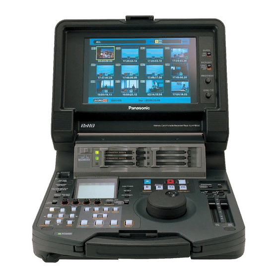
Introduction Features The AJ-HPM100 is a portable memory card recorder/player equipped with six P2 card (*) slots and a 9-inch color LCD monitor. Capability to record and play back audio and video in the compressed DVCPRO HD, DVCPRO50, DVCPRO and DV formats on six P2 cards (*) allow you to use the unit like a conventional editing VTR player. - Page 13 PC card slot for immediate access. The P2 card is a installed in the unit for playback in the desired order. ● Simplified audio split editing, voice-over recording and semiconductor memory card that Panasonic developed for professional AV use. playback functions provided The IN points for audio and video (audio IN point split) can be <About P2 cards>...
-
Page 14: Control Reference Guide
Control Reference Guide Audio and Video Controller CONTROL REMOTE LOCAL UNITY UNITY Headphones connector POWER switch AUDIO MONITOR SELECT button Turns the power on and off. Switches the audio signals to be output to the MONITOR L/R connectors and the headphones jack. Each press of the METER (FULL/FINE) selector button button switches the output signals to the MONITOR L/R Switches the scale of the audio level meter. - Page 15 METER SELECT switch UNITY/VAR channel select switches Switches to CH1-4 or CH5-8 in the audio meter and the UNITY: Plays back audio signals at a fixed level monitor. regardless of the positions of the audio level controls. 1(2): Plays back and outputs audio CH1(2) at INPUT SELECT buttons the level adjusted using the audio level Switch between video and audio input signals.
- Page 16 REW/PREV button COUNTER button Press to rewind. Select the speed in setup menu No. Press to switch the counter display of the LCD panel. 102 (FF. REW MAX). Each press of this button changes the counter display In the PB mode, hold down the SHIFT button and press as follows: [CTL (relative position from the beginning)] ➝...
-
Page 17: Gui Operations
GUI Operations 15 14 13 12 CONTROL REMOTE LOCAL UNITY UNITY 7 8 9 10 11 PLAY LIST button EXIT/CANCEL/PF button Press to create play lists or to play a created play list. When the PLAY LIST/ Press to return to the The PLAY LIST button lights and the play list screen THUMBNAIL buttons thumbnail display from... - Page 18 move to the previous recording slot position.Pressing MENU/DIAG button this button when the unit is in slot 1 results in a move to MENU button slot 6. Press this button to open the MENU. Press again to return to the previous screen. DIAG (SHIFT+MENU) button ENTRY/CLIP (LIST/PF2 button) Press to show information about this unit.
- Page 19 GO TO/MOVE button Use this button to move the IN point, SPLIT point, or OUT point of events registered in a play list. It can also be used for CUE UP when the THUMBNAIL and PLAY LIST buttons are off. Hold down the IN/OUT button and press the GO TO button to move and cue up to the IN and OUT points.
-
Page 20: Panel Control Unit And Card Slots
Panel Control Unit and Card Slots OFF ON CARD LOCK 9-inch Color LCD Monitor Stereo speakers Thumbnail screens facilitate video searches and Outputs the audio monitor sound. checks. LEVEL control Card Lock Adjusts the sound volume of the internal speaker and This lever locks the cards in place when the top panel headphones. -
Page 21: Lcd Panel
LCD Panel VIDEO AUDIO CMPST ANALOG 1394SG 1394SG SYSTEM 59.9450 1080i720p DVCPRO Level meter TV system display Indicates the level of audio signals for CH1, CH2, CH3 Indicates the selected TV system. Use the SYSTEM and CH4. setting No. 25 (SYSTEM FREQ) setup menu to switch The input signal level of audio signals is indicated between 59.94 Hz or 50 Hz. -
Page 22: Rear Panel
Rear Panel SERIAL DIGITAL COMPONENT AUDIO and VIDEO ANALOG AUDIO IN connectors/switches IN/OUT connectors Analog audio input connectors The input impedance of CH1-2 to CH3-4 can be These connectors enable input and output of serial switched. The LINE, MIC and 48V switches make it digital component audio and video signals. - Page 23 DC IN socket Remote control connector Connect a 12 V DC power supply here. Use an external This unit can be connected to an external controller to 12 V DC, 4.3 A (15 A peak or more) DC power supply. enable remote operation of the unit.
-
Page 24: Basic Setup
- In the EE mode, SDI, analog video output signals ANALOG COMPOSITE VIDEO IN connector and time codes become irregular. Do not use these Inputs analog composite video signals. signals for recording. • Unprocessed video and audio signals are output via the ANALOG COMPONENT VIDEO OUT connectors IEEE 1394 digital interface during SLOW and STILL Inputs analog composite video signals during output... -
Page 25: Side Panel
• For the latest information not available in the Operating Instructions, visit the P2 support desk at the following Web sites. For English: https://eww.pavc.panasonic.co.jp/pro-av/ USB 2.0 connector (Type A) Connect P2 store and USB 2.0 compliant hard disk drives for use in the USB host mode. -
Page 26: Moving Between Screens And Menu Operations
Moving Between Screens and Menu Operations Operating Modes This unit provide the three operating modes described below. Recording and Displays video and performs Use the THUMBNAIL and PLAY LIST buttons to select these playback modes recording or playback. modes. Lamps indicate which mode is currently engaged. Thumbnail mode Shows thumbnails of clips and manages clips. -
Page 27: Menu Operations
Menu Operations Press the MENU button in each mode to open the menu. Press the MENU button to open the menu. Perform menu operations as described below. Use the cursor buttons to place the cursor on menu items. ◆ NOTE: •... -
Page 28: Recording, Playback And P2 Card Handling
Recording, Playback and P2 Card Handling Insert a P2 Card Bend the protruding EJECT button downwards to the ◆ NOTE: right and set the card lock to ON. • When you use this unit for the first time, be sure to set the internal clock in setup menu No. -
Page 29: Removing P2 Cards
Removing P2 Cards Press the EJECT button to eject the P2 card. ◆ NOTE: • Do not remove P2 cards during access or during recognition directly after insertion (when the P2 card access LED flashes orange). Press the STOP button. When the P2 card access LED of a card to be removed flashes orange, press the STOP button to stop the... - Page 30 Instructions of P2 cards and SD memory cards, visit the P2 Orange light Reading and writing are possible. support desk at the following Web sites. The card is selected for For English: https://eww.pavc.panasonic.co.jp/pro-av/ recording. Flashes orange Reading and writing are possible. Flashes rapidly in P2 card is being recognized.
-
Page 31: Jog And Shuttle Operations Using The Search Dial
Jog and Shuttle Operations Using the Search Dial The search dial is used to search and check video. When the power is turned on, the search dial will not operate Each press of the dial alternates it between SHTL mode and unless it is first returned to the STILL position. -
Page 32: Clip Management
Clip Management Thumbnail and Clip Management 15 14 9 10 11 12 13 This unit provides a thumbnail screen for managing clips. A clip is a single data item that contains video, audio, metadata and other additional information. Normally, a clip is one shot generated from the start of recording until recording stops. -
Page 33: Thumbnail Screen Names And Functions
Thumbnail Screen Names and Functions Display status Thumbnail Display status indicates the type of thumbnails Indicates the initial frame of the clip that represents it. displayed on the screen. ALL: All clips Clip no. SAME FORMAT: Clips with the same format Indicates the numbers assigned to P2 card clips. - Page 34 P2 card slot number and hard disk drive status 2 3 4 5 6 P2 card and USB hard disk drive status is indicated as described below. The number of the P2 card slot that contains a P2 card is indicated in white. (white) The number of the P2 card slot of the P2 card that contains the clip at the cursor...
-
Page 35: Changing Thumbnail Display
Changing Thumbnail Display The thumbnail screen can be customized to suit operating Use the cursor buttons to select the clip type that conditions and improve efficiency. should appear under [THUMBNAIL]. Switching the Type of Information That is Displayed ALL CLIP: Show all clips SAME FORMAT Show clips in the same format as... - Page 36 TEXT MEMO IND.: Shows the text memo Setting Items to Display indicator Hides the text memo The thumbnail display can be customized to suit different indicator operating needs. The following describes procedures for changing thumbnail display indicators and data settings. WIDE IND.: Shows the wide indicator Hides the wide indicator...
-
Page 37: Selecting Clips
Selecting Clips Select clips for processing in the thumbnail screen as Canceling a Selection described below. Place the cursor on a selected clip and press the SET button again. This cancels the selection. ◆ NOTE: • Holding down the SHIFT button while pressing the EXIT button cancels made selections. -
Page 38: Playing Back Clips
Playing Back Clips Press the PLAY button Playback starts from the clip the cursor is on. After the clip at the cursor location has been played, subsequent clips are played back in order. When the last CONTROL REMOTE LOCAL clip has been played, the thumbnail screen appears. UNITY UNITY ◆... -
Page 39: Inserting Text Memos And Shot Marks
Inserting Text Memos and Shot Marks A text memo can be inserted in a clip to mark a specific Displaying Shot Marks location. The user can display shot marks to distinguish clips from each other. This function is not available on cards where the write protect switch has been set to PROTECT. -
Page 40: Copying Clips
Copying Clips Clips can be copied to a P2 card in any slot. ◆ NOTE: • To interrupt copying, press the SHIFT and EXIT buttons or the ◆ NOTE: SET button to cancel the job. • Take care not to turn off the power or remove a card during copying. The incomplete copy at the destination is deleted. -
Page 41: Deleting Clips
Deleting Clips Use the following procedure to delete a defective clip from a P2 card. Open the thumbnail screen. Select the clip to delete. Press the MENU button. Use the cursor buttons to choose [OPERATION] – [DELETE]. Select [YES] and press the SET button. This deletes all selected clips. -
Page 42: Repairing And Reconnecting Clips
Repairing and Reconnecting Clips ◆ NOTE: Repairing Bad Clips Incomplete clips occur under the following conditions. • When the individual clip segments on each P2 card that make up the This section describes how to restore bad clips that have clip are copied separately. -
Page 43: Viewing Clip Information
Viewing Clip Information Detailed clip information can be displayed on the screen. Clip no. Thumbnail Open the thumbnail screen. Clip information Place the cursor on the desired clip Indicates the number of indicators, inserted text memos and voice memos in a clip. The mark appears when Press the MENU button. - Page 44 Press the MENU button or the EXIT button to end GLOBAL CLIP ID: Global CLIP ID processing. (This is a unique number. There is no clip anywhere in the world with the same number.) USER CLIP NAME: The name a user assigns to a clip. This normally includes a GLOBAL CLIP ID.
-
Page 45: Attaching Metadata To Clips
P2 card. Download the latest version of P2 viewer from the URL given below. Select Method for Recording the USER English: https://eww.pavc.panasonic.co.jp/pro-av/ CLIP NAME Install P2 viewer on a PC, create a metadata upload file and Set the method for recording the USER CLIP NAME. - Page 46 Select [TYPE 1] or [TYPE 2] and press the SET Select Language for Metadata button. Recording method USER CLIP NAME to be Select the language used for showing metadata. recorded Use clip metadata TYPE 1 Read metadata settings Open the thumbnail screen. TYPE 2 Read metadata settings + COUNT value...
- Page 47 ■ Incrementing the COUNT value of the USER COUNT Value CLIP NAME for clips exceeding 4 GB In the following case, one shot is recorded as multiple clips The count value is indicated as a four-digit number. When and the COUNT value is automatically incremented and recording method “TYPE 2”...
-
Page 48: Loading Set Metadata Values
Loading Set Metadata Values Use the following procedure to load metadata from an SD Checking Set Metadata Values memory card. Use the following procedure to check set metadata values Insert the SD memory card storing the metadata stored in this unit. upload file. -
Page 49: Recording Clips Containing Metadata
Viewing Set Metadata Values Recording Clips Containing Use the cursor buttons to select a metadata item and Metadata press the SET button to view the information. USER CLIP NAME: The name the user assigned to a clip This procedure attaches the loaded metadata to clip that is CREATOR: Creator recorded. -
Page 50: Formatting P2 Cards
Formatting P2 Cards Open the thumbnail screen. Press the MENU button. Use the cursor buttons to choose [OPERATION] – [FORMAT] – [SLOTn] (the number of the P2 card slot containing the card to format) and press the SET button. Select [YES] and press the SET button. The card is now formatted. -
Page 51: Checking Card Status
Checking Card Status Use the following procedure to display P2 card slot status and P2 card usage and other card information on the screen for checking. Selecting Information to Display Select whether remaining capacity or used capacity should appear in the P2 card information. Open the thumbnail screen. -
Page 52: Displaying Card Status Information
Displaying Card Status Information After completing the settings described on the previous page, you can use the procedure described below to check the Write protect mark status of P2 cards in P2 card slots. A write-protected P2 card is indicated by the mark displayed here. -
Page 53: Using Play List
Using Play List Play List Function The play list function allows you to create lists (play lists) that register clip sections recorded on the six P2 cards to continuously play them back in list order. In normal playback, playback starts from the starting point and goes on until the last clip. -
Page 54: Play List Screen Names And Functions
Play List Screen Names and Functions Display status Total play list time The following type of event screens are displayed. Indicates the total play time of all events. PLAYLIST: Event list EVENT PROPERTY: Detailed event information Time line display P2/USED(REMAIN): Media information (amount of The events appear in the time line around the event at space used/free space) the cursor position. -
Page 55: Stop Mode Setup
Filename Start TC Shows the number of the P2 card slot where the Displays the start time code value for changing the current play list is stored and its filename. time code during playback. P2 card slot number: Filename P2 cards slot and file name Normal REMAIN(EXTRA) are displayed in white:... -
Page 56: Buttons Used In Play List Operations
Buttons Used in Play List Operations 18,19 20,21 CONTROL REMOTE LOCAL UNITY UNITY 10 11,12 ▲▼ b a Cursor buttons PLAY LIST button Press to switch to play list mode. This button lights in In the play list, press this button to move the play list the play list mode. - Page 57 ENTRY button ◆ NOTE: ENTRY + IN/OUT • At a 24PN frame rate, you can change the frame rate in Use these functions to create play list events. In the event multiples of 4 frames. register mode (when the EVENT button is on), hold down the ENTRY button and press the IN (OUT) button to UNITY/VAR/channel select switches and audio register an IN (OUT) point.
- Page 58 INSERT button Use this button to add a new event when the play list is displayed. Place the cursor on the line in the play list where you want to insert a new event and press this key to switch to the screen for adding and registering the event.
-
Page 59: Creating Play Lists
Creating Play Lists The workflow for creating a play list is given below. A play list can be up to 24 hours long. You cannot create a play list that is longer than 24 hours. Preparing new play lists ↓ Registering events and adding existing play lists ↓... -
Page 60: Registering Events For Selected Clips
Registering Events for Selected Clips Use the following procedure to add selected clips to the play Press the SET button. list. This operation registers the start of a clip as the IN point This registers an event where the start of the clip is the IN and its end as the OUT point. -
Page 61: Registering Events From Video
Registering Events From Video You can specify an IN point and OUT point while playing back Press the EVENT button to end registration. a video and register this as an event. ◆ NOTE: • Set the IN point and OUT point so that the resulting event has a duration of at least 10 frames. -
Page 62: Importing And Adding To Existing Play List Files
Importing and Adding to Existing Play List Files This section describes how to import play lists stored on a P2 ◆ NOTE: card and how to add an event at the cursor location. • You cannot import a play list file whose format differs from the format of the current play list. -
Page 63: Saving Play Lists
Saving Play Lists Use the following procedure to save a play list stored in the ◆ NOTE: play list area of memory in this unit to a P2 card. • The filename is automatically generated and cannot be changed. Changing the filename on a PC will make it impossible Open the play list screen. -
Page 64: Editing Play Lists
Editing Play Lists Play lists can be edited in a number of different ways. Opening an Existing Play List File Open the play list screen to view the play list in the play list Select [YES] in the confirmation screen and press area of memory in this unit. -
Page 65: Changing Event In And Out Points
Changing Event IN and OUT Points You can change the IN and OUT points for a play list event Register a new IN point. during video playback. Use the operation buttons or search dial to look for a location to start an event. Then hold down the IN button and press the ENTRY button. -
Page 66: Changing Event Order
Press the ENTRY button to finalize the change. • Performing any of the following operations will discard the changes and make you return to the play list screen. - Pressing the EXIT button. ◆ NOTE: - Holding down the SHIFT button and pressing the EXIT button. •... -
Page 67: Deleting Events
Deleting Events You can use the following procedure to delete events in the Use the cursor buttons to choose [OPERATION] – play list. [DELETE SELECTED EVENT]. Press the SET button. Select [YES] in the delete confirmation screen and press the SET button. This deletes all selected events. -
Page 68: Saving Events
Select [YES] in the delete confirmation screen and press the SET button. This deletes all play list events. Saving Events While editing a loaded play list file or the play list file has been saved using [FILE] – [SAVE AS], the file can subsequently be saved using the following procedure. -
Page 69: Audio Split Editing
Audio Split Editing Use audio split to shift the audio IN point relative to the video IN point (audio IN point split). Note that audio channels cannot be selected in this procedure. This function is performed on all channels together. Play list example 1 Play list example 2 New play list event... -
Page 70: Registering From Video
Registering From Video Use the following procedure to newly register an event Press the EVENT button to end registration. containing an audio split. ◆ NOTE: ◆ NOTE: • In the split display, “–” indicates forward while “+” indicates • Refer to the “Revising Split points” section to add an audio split to a reverse direction. -
Page 71: Revising Split Points (Changing Registered Point)
Revising Split Points (Changing Registered Point) You can add an audio split to an event registered in the play Open the play list screen. list and change the audio split point. Use the cursor buttons to select the event where you want to add (or change) a split point. -
Page 72: Cancelling An Audio Split Setting
Cancelling an Audio Split Setting Use the following procedure to cancel an audio split setting. Open the play list screen. Use the cursor buttons to select the event where you want to cancel the split setting. Hold down the SHIFT button and press the RESET button. -
Page 73: Simplified Voice-Over
Simplified Voice-Over This function allows you to make voice-overs and give priority to the voice-over during playback. Recording is performed on one or two channels. The channel input during recording can be mixed with the playback sound. • The maximum number of voice-overs is 99. ◆... -
Page 74: Voice-Over From Still Image Status
Voice-Over From Still Image Status Find the location for the voice-over. Use the operation buttons or the search dial to find a location for a voice-over and press STILL Press the A.DUB button. This generates an A DUB PAUSE state while a still image is output at the still location. -
Page 75: Displaying Voice-Over Events
Displaying Voice-Over Events The voice-over appears in the play list screen as shown below. Use the following procedure to change offset and duration. Play List • The voice-over is added to the line after an event with an A normal event audio start point. -
Page 76: Viewing Event Information
Viewing Event Information Indicating Event Property You can use this function to view and confirm miscellaneous ◆ NOTE: event information. • Holding down the SHIFT button in step 2 while pressing the SPLIT button will also open the event information screen. •... -
Page 77: Event Review
Event Review You can use this function to check the content of an event by playing if from its IN point to its OUT point. Open the play list screen. Use the cursor buttons to select the clip you want to review. -
Page 78: Playing Back Play Lists
Playing Back Play Lists Setting the Playback Time Code (TC) During play list playback, you can select whether the time Use the cursor buttons to choose [SETTING] – code should be replaced and output as a continuous value or [REPLACE TC] – [START TC] and press the SET the time code of each clip should be output. -
Page 79: Playing Back The Play List
Playing Back the Play List Use the following procedure to play back the play list. Press the PLAY button. Playback starts from the cursor location and continues until the end of the play list or until all playable events have been played. -
Page 80: Creating New Clips From The Play List (Edit Copy)
Creating New Clips From the Play List (Edit Copy) You can use the play list to create a new clip. ◆ NOTE: This function is called edit copy. • If there is not enough free space left on the P2 card where edit copy will save the data, “WARNING: LACK OF REC CAPCITY!”... -
Page 81: Using Usb Connectors And Sd Memory Cards
USB (USB 2.0) driver be installed. Use of P2 viewer, which can be downloaded from the following site, allows you to manipulate clips stored on a P2 card on a Windows PC. http://panasonic.biz/sav/p2/ ◆ NOTE: USB2.0 • For details regarding connections, refer to the Operating Instructions supplied with the PC and the application software. -
Page 82: Connecting A Pc To This Unit
Connecting a PC to This Unit Switching to USB Device Mode Select [USB DEVICE] in the confirmation screen and press the SET button. CONTROL REMOTE LOCAL UNITY UNITY USB HOST USB DEVICE CANCEL “USB DEVICE” flashes on the LCD monitor to indicate that the unit is entering the USB host mode. -
Page 83: Using This Unit With A Hard Disk
• A hard disk is a precision instrument whose read and write functions may fail in some operating environments. Please note that Panasonic accepts no liability whatsoever for data loss or other losses either direct or indirect arising from hard disk damage or other defects. -
Page 84: Switching To Usb Host Mode
Switching to USB Host Mode Use USB host mode operations. ◆ NOTE: • While P2 cards played back in USB host mode will appear on the LCD monitor, the inputs and output on the rear panel will not CONTROL work. REMOTE LOCAL •... -
Page 85: Exporting To A Hard Disk In Card Units
When the confirmation message appears again, select [YES] and press the SET button. This starts hard disk formatting. Exporting to a Hard Disk in Card Units A TYPE S hard disk allows you to export data to a hard disk Select [YES] and press the SET button. -
Page 86: Displaying Hard Disk Information (Explorer Screen)
Displaying Hard Disk Information (Explorer Screen) Use this function to view hard disk information. Display status The name of the screen (HDD-EXPLORE) Switch to the USB host mode. Disk information The following information appears. Connect a USB hard disk. Hard disk that PARTITION: TYPE S/ makes it possible... -
Page 87: Displaying Clip Thumbnails On A Hard Disk
Displaying Clip Thumbnails on a Hard Disk You can display thumbnails and manage clips stored on the VERIFY: Verify setting and result at time of hard disk in the same way as clips on P2 cards. recording ON: FINISHED Verification was Open the explorer screen. -
Page 88: Importing Data From The Hard Disk To A P2 Card
Importing Data from the Hard Disk to a P2 Card Importing Data in Partition units from TYPE Importing Data to a P2 Card in Clip Units S Hard Disks and P2 Store You can select a hard disk clip and import it to a P2 card. You can import (loading data from a hard disk to a P2 card) Insert the P2 card where the data will be imported to. -
Page 89: Using Sd Memory Cards
Using SD Memory Cards You can use SD memory cards on this unit. NUMBER OF CLIPS: The number of clips on an SD memory card when clips have been copied to an SD memory Displaying Miscellaneous SD card using a proxy or a P2 Memory Card Information camera recorder. -
Page 90: Unit Setup
Setup Unit Setup The settings for this unit consist of SYSTEM, BASIC, OPERATION, INTERFACE, TIME CODE, VIDEO, AUDIO, DIF and MENU. The SYSTEM setting values are stored in the SYSTEM file. The other setting values are stored in the user setting file. Up to five user files (USER1 to USER5) can be saved. -
Page 91: Changing Settings
Changing Settings The menus on the LCD monitor or a monitor (when the SUPER switch on the right side of the LCD monitor is set to “ON”) connected to the ANALOG COMPOSITE MONITOR OUT connector make it possible to change settings. Change Operations Select items to change. -
Page 92: Using A Lock To Protect The User Setting File
following operation to change setting values. Making changes using the PF buttons ➝For details on how to assign items to the PF button, refer to “Setup menu No. A04 to A06 (PF1 ASSIGN to PF3 ASSIGN).” Press the PF (EXIT) button. Registered items appear on the LCD monitor. -
Page 93: Item Settings
1: 50Hz 0001 SYSTEM FREQ NOTE: For AJ-HPM100E Changing this item will only cause the menu item to flash but the setting is not actually 0000 59.94 reflected to this unit. For the changes to take effect, turn the power off and turn it back 0001 on again. - Page 94 Item Setting Settings and brief function description SUPER SUPER DISP. DISP. 0000 Specifies whether or not HD output should advance 90H phase relative to SD REF input during SD REF input. 0001 0: Outputs HD at the same phase as SD REF. 1: HD output is output at a phase that is 90H advanced relative to SD REF.
-
Page 95: Basic
BASIC This menu sets buttons available on the key panel in REMOTE mode, switches display of the CTL counter display between 12 and 24-hour clock display, sets superimposed display, character displays in superimposed display, SETUP-MENU and other displays, sets recording formats, sets the formats that can be added to the play list and sets the time of the internal clock. * An underlined setting indicates an initial value. - Page 96 Item Setting Settings and brief function description SUPER SUPER DISP. DISP. 0000 Specifies the vertical character position output via the VIDEO MON connector or displayed in the superimposed display of the LCD panel. 0020 CHARA V-POS 0022 0000 WHITE Specifies the display type output via the VIDEO MON connector or in the superimposed display, SETUP-MENU and other LCD panel displays.
- Page 97 Item Setting Settings and brief function description SUPER SUPER DISP. DISP. Subscreen 0000 2000 Sets the year. YEAR 0030 2030 0001 Sets the month. NOTE: MONTH 0012 Setting a nonexistent day for February, April, June, September and November will automatically set the equivalent day in the following month. 0001 Sets the day.
-
Page 98: Operation
◆ NOTE: Time difference City/Region –02:30 • The clock is accurate to within about ±30 seconds a month with the –02:00 Central Atlantic time power off. • When the precise time is required, check and reset the time while –01:30 the power is on. - Page 99 SUPER SUPER DISP. DISP. 0000 Select whether recording and stopping should be performed automatically according to the Recording Marks in the HD SDI input signals from Panasonic camera-recorders. 0001 TYPE1 0: No automatic recording/stopping 0002 TYPE2 1: Recording and stopping is performed automatically according to the Recording Marks in the LTC information attached to HD SDI signals.
-
Page 100: Interface
1: DVCPRO 0002 ORIG 2: ORIG ID SEL NOTE: • Select [OTHER] for ID data for a VTR other than a DVCPRO. • Select [ORIG] only when specific Panasonic controllers (such as AJ-A850, separately sold accessory) are connected. Setup: Item Settings... -
Page 101: Time Code
TIME CODE This menu sets the time code. * An underlined setting indicates an initial value. Item Setting Settings and brief function description SUPER SUPER DISP. DISP. 0000 BLANK Specifies whether or not a VITC signal will be output at the positions selected in menu No. 0001 THRU 501 VITC POS-1 and No. - Page 102 Item Setting Settings and brief function description SUPER SUPER DISP. DISP. 0000 Specifies user bit usage in time code generated by the TCG. 0: NOT SPECIFIED (character set not specified) 0001 1: ISO CHARACTER (8-bit character set complying with ISO646 and ISO2022) 0002 2: UNASSIGNED 1 (undefined) 0003...
-
Page 103: Video
Definition of terms: SBC (Sub Code Data) area: This area, which is separate from video and audio data area on a P2 card, stores SMPTE/ EBU compliant time code, recording dates and other information. VAUX (Video Auxiliary Data) area: An area in the video data area on a P2 card that stores additional information on video data. - Page 104 Item Setting Settings and brief function description SUPER SUPER DISP. DISP. 0000 CMPNT Sets the level adjustment mode. STYLE 0001 CMPST 0: Level adjustment mode for the component style 1: Level adjustment mode for the composite style 0000 Pb-Pr Specifies the rotational axis of chroma phase adjustment. 0001 0: Rotates in a perfect circle in an SDI (component style) vectorscope.
- Page 105 Item Setting Settings and brief function description SUPER SUPER DISP. DISP. Adjusts the chroma level (– ∞ to 0 dB to +3 dB). 0000 0.0% NOTE: 1000 100.0% C LEVEL • This setting is available when CMPST is set in menu No. 650 STYLE. •...
- Page 106 Item Setting Settings and brief function description SUPER SUPER DISP. DISP. 0000 Specifies whether or not EDH is superimposed on serial output signals. EDH(SD) 0001 0: Signals are not superimposed. 1: Signals are superimposed. 0000 Specifies the operating mode for edge subcarrier reduction (ESR) in the playback circuit. 0001 AUTO 0: ESR is forcibly set to off.
-
Page 107: Audio
AUDIO This menu is used for audio settings. * An underlined setting indicates an initial value. Item Setting Settings and brief function description SUPER SUPER DISP. DISP. 0000 Specifies the standard level for audio input (CH1). 0001 CH1 IN LV 0002 –3dB 0003... - Page 108 Specifies the standard level. 0: 20 dB 0001 FS-18 1: 18 dB 0002 FS-12 2: 12 dB REF LEVEL For AJ-HPM100E 0000 FS-20 0001 FS-18 0002 FS-12 0000 Turns on and off the CH2 microphone power supply. CH2 MIC PWR 0001 0: Does not use the microphone power supply.
-
Page 109: Dif
Item Setting Settings and brief function description SUPER SUPER DISP. DISP. 0000 Specifies whether or not the playback sound be mixed in the voice-over. 0: Playback sound is not mixed. 0001 1: The input and playback sound are mixed in the recording. A DUB PB MIX NOTE: Press the STOP or SET button to open the subscreen to select the channels that will be... -
Page 110: Menu
Item Setting Settings and brief function description SUPER SUPER DISP. DISP. 0000 DFLT Specifies the extension menu. Normally, DFLT is used. 0001 DIF CONFIG 0255 0000 CH1+2 Specifies the output channels when the audio signals are in 4-channel mode and output in the DVCPRO (25 Mbps) format and a DV clip is played back. -
Page 111: Time Code, User Bit And Ctl
Time Code, User Bit and CTL Use the setup menu No. 504 (RUN MODE) to set the Time code run mode for the time code generator. The time code is used when the time code signal generated REC: The internal time code generator advances by the time code generator is to be recorded. - Page 112 Setting the external time code Set the TCG switch to [EXT]. (External time code selection) Make the following settings in setup menu No. 507 (EXT TC SEL). EXT_L: The LTC signal input to the TIME CODE IN connector (BNC) on the rear panel is recorded as TC.
- Page 113 Menu Menu Recorded time code Selected video No. 507 EXT No. 518 VITC switch input signal SBC area VAUX area TC SEL Time code on IEEE1394 digital input 1394 (VAUX area) HD SDI SVITC on input video signal *3 Internal TCG value CMPST / SD SDI VITC on input video signal *3 (REGEN /...
- Page 114 CTL Mode Engage the stop mode. Use the COUNTER button to select [CTL]. During playback, the counter displays the play position relative to the start position. Recording starts from the counter value [0:00:00:00]. When recording stops, the counter shows the position relative to the start position.
-
Page 115: Superimpose Screen
Superimpose Screen Control signals, time code and other information are indicated Display Position by abbreviations. Use setup menu No. 007 (CHARA H-POS) and No. 008 Display monitor (CHARA V-POS) to change the position of characters in the superimposed display. Abbreviation Display monitor Display monitor Abbreviations:... -
Page 116: Audio V Fade Function
Audio V Fade Function This section describes the differences between audio processing provided by setup menu No. 731 (PB FADE) settings. Setup menu No. 731 (PB FADE) settings make it possible to perform audio V fade or cut processing between clips and events during clip selection and playback or play list playback. -
Page 117: Audio Recording Channels Selection
Audio Recording Channels Selection Audio Recording Channels Depending on setup menu 725 - 728 (REC CH1 to 4) settings, the INPUT SELECT button on the front panel allows you to select the following input signals. When 1394 is selected, the input signal is recorded in its original form regardless of setting. -
Page 118: Condensation
For Long and Trouble-Free Operation Condensation Condensation occurs due to the same principle involved when droplets of water form on a window pane of a heated room. It occurs when this unit or a card is moved between places where the temperature or humidity varies greatly or when, for instance: •... -
Page 119: Error Messages
Error Messages When a warning occurs in this unit, the error number is DIAG menu indicated on the counter display. Open the DIAG menu to view a description of the error on the counter display or a LCD This menu shows deck information. Deck information includes monitor. -
Page 120: Warning Information Display
WARNING information display • A warning message is displayed whenever a warning occurs. When no warnings have been detected, “NO WARNING” is displayed. • When multiple warnings occur, turn the search dial to check the descriptions of each warning. If “T&S&M” is selected in setup menu No. 006 (DISPLAY SEL), a message appears in the mode display whenever a warning or error occurs. - Page 121 Counter Priority Monitor display Description Deck operation display Displayed for two seconds when a text memo is added. Operation TEXT MEMO TEXT MEMO continues Displayed for two seconds when a shot mark is added or deleted. Operation MARK ON / MARK ON/OFF continues MARK OFF...
- Page 122 ◆ NOTE: *1 This warning appears only during recording. Then the video recording goes black and the audio signal is muted. *2 This warning appears only during recording. Then the audio is recorded mute. *3 This warning appears only during recording. The internally generated time code is recorded. *4 This warning appears at any time.
- Page 123 Item Message Description Measure CANNOT The destination target cannot be properly Reboot the hard disk or connect a different hard disk. RECOGNIZE HDD! recognized. CANNOT ACCESS An error occurred during P2 card access. Check P2 card. CARD! MISMATCH Copying cannot be made because the Use a P2 card with appropriate capacity.
-
Page 124: Hours Meter" Information Display
Item Message Description Measure LACK OF REC The card selected for edit copying does not have Insert a card with sufficient capacity. Play list CAPACITY! enough capacity. Error information Error Description Operation Remarks Message Displayed when an error occurs in reading and writing card data. STOP E-30 TURN POWER OFF... -
Page 125: Updating The Firmware In This Unit
Visit the web site listed below and go to P2 support desk page for the latest information on firmware. English: https://eww.pavc.panasonic.co.jp/pro-av/ Before updating the firmware, check firmware version of the unit in the [PROPERTY-SYSTEM INFO] in the thumbnail menu. Then access the site listed above to download the firmware if necessary. -
Page 126: Specifications
Specifications GENERAL Recording Card Number Recording format Power supply: 100-240 V AC, 50/60 Hz, 60 W times: model DVCPRO DVCPRO DVCPRO 12 V DC, 4.3 A (full options) Cards (2-channel 50 (4- HD (8- audio) channel channel indicates safety information. audio) audio) approx. - Page 127 AUDIO DIGITAL AUDIO MIC: –60 dBu MIC+48V: fantom +48V supported, –60 dBu Sampling frequencies: SDI input: BNC × 1, complies with SMPTE 292M/296M/ 48 kHz (synchronous with video) 299M during HD SDI input, complies with Quantizing: 16 bits SMPTE 259M-C/272M-A (480/59.94i), ITU-R Frequency response: BT.656-4 (576/50i) during SD SDI input 20 Hz to 20 kHz ±1.0 dB...
-
Page 128: Menu Index
Menu index Thumbnail menu Play list menu THUMBNAIL .................35 FILE ..................59 ALL CLIP................35 NEW ..................59 SAME FORMAT CLIPS............35 OPEN ................64 SELECTED CLIPS .............35 APPEND................60 MARKED CLIPS ..............35 SAVE .................68 TEXT MEMO CLIPS............35 SAVE AS ................63 SLOT CLIPS ..............35 OPERATION .................60 SETUP ................36 DELETE ALL EVENT ............67 ALL HIDE...............36... - Page 129 MEMO...
- Page 130 PANASONIC BROADCAST & TELEVISION SYSTEMS COMPANY UNIT COMPANY OF PANASONIC CORPORATION OF NORTH AMERICA Executive Office: One Panasonic Way 4E-7, Secaucus, NJ 07094 (201) 348-7000 EASTERN ZONE: One Panasonic Way 4E-7, Secaucus, NJ 07094 (201) 348-7196 Southeast Region: (201) 348-7162 WESTERN ZONE: 3330 Cahuenga Blvd W., Los Angeles, CA 90068 (323) 436-3500...