Advertisement
Quick Links
Download this manual
See also:
Service Manual
SPECIFICATIONS
CONTENTS
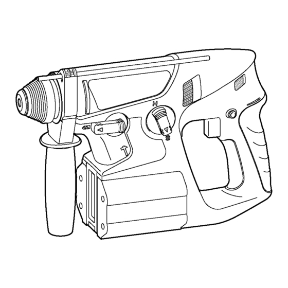
Cordless Rotary Hammer
EY6813-U1
Page
2
2
3
6
© 2002 Matsushita Electric Works Ltd. All rights
reserved. Unauthorized copying and distribution is a
violation of law.
ORDER NO.PTD0212U38C1
F16
Page
8
9
10
Advertisement
Troubleshooting

Related Manuals for Panasonic EY6813-U1


Summary of Contents for Panasonic EY6813-U1
-
Page 1: Table Of Contents
CONTENTS 1 SCHEMATIC DIAGRAM 2 WIRING CONNECTION DIAGRAM 3 DISASSEMBLY/ASSEMBLY INSTRUCTIONS 4 TROUBLESHOOTING GUIDE Cordless Rotary Hammer EY6813-U1 Page 5 TRIAL OPERATION(after checking TROUBLESHOOTING GUIDE.) 6 EXPLODED VIEW 7 REPLACEMENT PARTS LIST © 2002 Matsushita Electric Works Ltd. All rights reserved. -
Page 2: Schematic Diagram
EY6813-U1 1 SCHEMATIC DIAGRAM 2 WIRING CONNECTION DIAGRAM... -
Page 3: Disassembly/Assembly Instructions
3. Pluck the chuck cover depressing the chuck handle. 4. Remove 15 housing screws. For assembling NOTE : Make sure to attach the dust preventive clothes or filters on the housings. Removal of the motor brush assembly. 1. Loosen 2 screws. EY6813-U1... - Page 4 EY6813-U1 IHOW TO DISASSEMBLE MAIN UNIT. Ref. No. 2A Procedure 1A→ → → → 1B→ → → → 2A Procedure 1A→ → → → 1B→ → → → 2A→ → → → 2B Ref. No. 2B Removal of the switch.
- Page 5 In addition, hammer O-ring, inside of piston and cylinder for output shaft block also need to apply. Air compressed by the piston drives hammer. Take care to protect the piston and hammer from contamination by dust. EY6813-U1...
-
Page 6: Troubleshooting Guide
EY6813-U1 4 TROUBLESHOOTING GUIDE (Refer to WIRING CONNECTION DIAGRAM) 4.1. CHECK POINTS FOR ELECTRICAL PARTS. < TROUBLE > Does not operate. → If no less than 24V DC is available across the (+) and (-) Does not speed- → control but switch trigger works properly. - Page 7 <CHECK INTERMEDIATE SHAFT ASSEMBLY.> <CHECK BEARING.> ↓OK <CHECK O-RING.> ↓OK <CHECK RECIPROCATION BEARING.> ↓OK <CHECK STRIKER.> <CHECK BEARING.> ↓OK <CHECK INTERMEDIATE SHAFT ASSEMBLY.> EY6813-U1 < REMEDY > NO Replace → intermediate shaft assembly. NO Replace universal → coupling. NO Replace piston →...
-
Page 8: Trial Operation(After Checking Troubleshooting Guide.)
EY6813-U1 5 TRIAL OPERATION(after checking TROUBLESHOOTING GUIDE.) 5.1. HAMMER/DRILL Confirm the action when setting the H/D handle to HAMMER mode. Rotation with hammering when the drill bit touches something like stone, and power. It is OK, if it takes about 7-10 seconds by 20kgf to hole ( Confirm the action when setting the H/D handle to DRILL mode. -
Page 9: Exploded View
EY6813-U1 6 EXPLODED VIEW... -
Page 10: Replacement Parts List
EY6813-U1 7 REPLACEMENT PARTS LIST NOTE: *B=only available as set *C=available individually Ref.No. Part No. WEY6813K3078 WEY6813H3117 WEY6813K3127 WEY6813L0427 WEY6813L1917 WEY6813L0437 WEY6813L0917 WEY6813L0367 WEY6813L4058 EY6812L0387 WEY6813L4067 EY6812L4627 EY6812L0977 WEY6813L1247 WEY6813L1257 EY6812L0847 WEY6813L4077 WEY6813L0467 WEY6813L0017 WEY6813L0027 WEY6813L0987 WEY6813L9557 WEY6813L0357 WEY6813L4627 WEY6813L4987...