Table of Contents
Advertisement
This service information is designed for experienced repair technicians only and is not designed for use by the general public.
It does not contain warnings or cautions to advise non-technical individuals of potential dangers in attempting to service a product.
Products powered by electricity should be serviced or repaired only by experienced professional technicians.Any attempt to service
or repair the product or products dealt with in this service information by anyone else could result in serious injury or death.
SERVICE MANUAL
WARNING
year (full name of the company who issues the service information).
All rights reserved.Unauthorized copying and distribution is a violation of law.
Haier Group
TL1409S005V1.1
Heat Pump Dryer
Model No.:
HD80-26A
HD80-26A-F
HD80-26A-DF
Advertisement
Table of Contents

Related Manuals for Haier HD80-26A


Summary of Contents for Haier HD80-26A
-
Page 1: Document Control
SERVICE MANUAL TL1409S005V1.1 Heat Pump Dryer Model No.: HD80-26A HD80-26A-F HD80-26A-DF WARNING This service information is designed for experienced repair technicians only and is not designed for use by the general public. It does not contain warnings or cautions to advise non-technical individuals of potential dangers in attempting to service a product. -
Page 2: Table Of Contents
Issue Service Manual Rev. Model No: 26A SERIES Table of Contents Document control ......................1 Chapter 1. General Information ................... 2 1-1. Table of Contents 1-2. General Guidelines 1-3. Caution and Warning symbols 1-4. Function indication symbols Chapter 2. Product Feature ..................4 2-1. -
Page 3: General Guidelines
Service Manual Issue Rev. Model No: 26A SERIES 1-2. General Guidelines When servicing,observe the original lead dress.If a short circuit is found, replace all parts which are overheated or damaged by the short circuit.After servicing ,see to it that all the protective devices such as insulation barriers ,insulation papers shields are properly installed . -
Page 4: Chapter 2. Product Feature
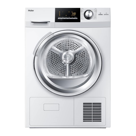
Issue Service Manual Rev. Model No: 26A SERIES Chapter 2. Product Feature 2-1. Features and theory Heat pump tumble dryer Energy class A+++ LED Display Delay time adjustable 1 airflow circuit 2 compressor 3 fan 4 drain pump 5 condenser 6 accessorial condenser 7 motor fan 8 refrigerant circuit... -
Page 5: 2-2.Specification
Service Manual Issue Rev. Model No: 26A SERIES 2-2. Specification HD80-26A-F Front loaded dryer Product identification Description of appliance Dryer Type of appliance (FS = standing, BI = built-in) Supplier own brand Haier Supplier bar code (TBC) Commercial Brand / Model... - Page 6 Service Manual Issue Rev. Model No: 26A SERIES Basics data Unit dimensions (H x W x D) 84.5x 59.5 x65 Net weight 50.5 Voltage/frequency V/Hz 220~240V/50Hz Input power(Max) 800W Control M = electromechanical, E=electronic,F=fuzzy Drum S = stainless steel / Z = zinc coated Door: aesthetic (R=round, Y=big eye, Q = square)
- Page 7 Service Manual Issue Rev. Model No: 26A SERIES 2-2. Specification Function n° Function Selection n° Dry Level n° Mode n° Timer n° Start/Pause button Power button - 7 -...
-
Page 8: Chapter 3. Important Safety Instructions
Issue Service Manual Rev. Model No: 26A SERIES Chapter 3. Important Safety Instructions 3-1 Before switching the device on for the first time 1.Ensure that the device is installed and electrically grounded by a qualified service person in accordance to local codes to prevent shock hazard and assure tability during operation. 2.Install this tumble dryer properly in accordance with the installation instructions before use. -
Page 9: Chapter 4. Operation Instructions
Issue Service Manual Rev. Model No: 26A SERIES Chapter 4. Operation instructions 4-1 Control panel Synthetic Cotton Extra Dry Extra Dry Ready to Ready to Store Store Ready to Ready to Iron Iron Wool Towel Duvet Sport Microfiber Shoe Underwear Function Selection Dry Level... - Page 10 Issue Service Manual Rev. Model No: 26A SERIES 4.1.3 Programme Turn the knob to choose the desired drying program.There are 16 progrmme options. Synthetic Cotton Extra Dry Extra Dry Ready to Ready to Store Store Ready to Ready to Iron Iron Wool Towel...
-
Page 11: Display Screen
Issue Service Manual Rev. Model No: 26A SERIES 4.1.4 Display screen Function Selection Dry Level Mode Timer 10 11 Child-lock indicator To activate the Child-lock function after a cycle has been started, press the Fu has been started, press the nction &... - Page 12 Issue Service Manual Rev. Model No: 26A SERIES 4.1.5 Function button 7/8 Function and Selection button There are 4 functions you can choose Function and Selection are a couple of buttons.They should be selected together. Press the function button to select one function you need-corresponding indicator icon is flashing,then press Selection button-corresponding icon lights up.
-
Page 13: Using The Tumble Dryer
Issue Service Manual Rev. Model No: 26A SERIES 4-2 Using the tumble dryer 4.2.1 Connect the tumble dryer to the power supply (220V to 240V~/50Hz). 4.2.2 Loading the tumble dyer 4.2.3 Switch on the power supply 4.2.4 Selecting program,selecting functional Synthetic Cotton Extra Dry... -
Page 14: Chapter 5. Part Identification
Issue Service Manual Rev. Model No: 26A SERIES Chapter 5. Part Identification drawer hold the drawer,the tank can be pulled control panel outwards front panel handle pull the handle , the door can be opened. outer frame of sight window screen of sight window you can see the loading through the window service panel... - Page 15 Issue Service Manual Rev. Model No: 26A SERIES fortified panel drum belt motor capacitor foot refrigerant(134A) filter compressor pump box of container wheel support the drum base part condenser evaporator -15 -...
- Page 16 Issue Service Manual Rev. Model No: 26A SERIES cover of air channel motor fan belt pulley belt pulley process fan belt lamp cover unscrew 2 screws from the cover, it can be opened,the light can be replaced. hook of basket filter humidity sensor seal felt...
-
Page 17: Chapter 6. Disassembly Guide
Issue Service Manual Rev. Model No: 26 SERIES Chapter 6. Disassembly Guide 6-1 Control panel 1) Unscrew 2 screws on the back push of the top plate. 2) Pull the top plate backward and upward as shown. Pull out the tank. 1) Unscrew 2 screws on the top of the control panel. -
Page 18: Bearing And Process Fan
Issue Service Manual Rev. Model No: 26A SERIES 6-2 Bearing and process fan 1) Unscrew all the screws around the belt cover and the back cover. 1) Remove the blet; 2)Unscrew the 2 screw near the bearing; 3) Unscrew the screw near the pulley. 1)Unscrew 2 screws around the pulley;... -
Page 19: Motor
Issue Service Manual Rev. Model No: 26A SERIES Unscrew 4 screws on the holder for bearing. The bearing can be disassembled. bearing 6-3 Motor 1) Disassemble the top cover; 2) Disassemble the front panel; 3) Unscrew 5 screw fastening the front girder. - Page 20 Issue Service Manual Rev. Model No:26A SERIES 1)Disconnect the wire of motor ; 2)Disassemble the spring drum belt. 3)Unscrew 2 screws fastening the motor. 1)Unscrew the nut fastening the motor belt pulley and remove the pulley. 2)Disassemble the wire of capacitor; 3)Unscrew 2 screws fastening the support of capacitor and remove it.
-
Page 21: Pump
Issue Service Manual Rev. Model No: 26A SERIES 6-4 Pump 1) Unscrew 2 screws on the support of pump. 2) Seperate the pipe and pump; 3) Disconnect the wire of pump. The pump assembly can be taken out. 6-5 Front air channel 1) Remove cooling grid ;... - Page 22 Issue Service Manual Rev. Model No: 26A SERIES Unscrew 2 screws on the hinge, disassemble the door. Turn the four spanners anticlockwise and you can take the filter assembly out. Unscrew all the screw on the front panel and disassemble it. -22 -...
-
Page 23: Belt
Issue Service Manual Rev. Model No: 26A SERIES Unscrew 3 screws on the front air channel. The front air channel can be disassembled. 6-6 Belt The belt can be disassembled. -23 -... -
Page 24: Pcb
Issue Service Manual Rev. Model No: 26A SERIES 6-7 PCB Unscrew 7 screws on the PCB box. 2.Disconnect the lead between the PCB and the touching broad. 3. The PCB assembly can be disassembled. Romove the ring. 1. Romove the knob. 2. -
Page 25: Base Assembly
Issue Service Manual Rev. Model No: 26A SERIES 6-8 base assembly Instruction: 1) All the tubes can be welded together to be a heat pump system; 2) Every part in the base assembly can be applied as spareparts; 3) The refrigerant charged is R134A. 4) The system air pressure should be less than 15Pa before charging R134A;... - Page 26 Issue Service Manual Rev. Model No: 26A SERIES seal bar -26 -...
-
Page 27: Chapter 7. Schematic Diagram
Issue Service Manual Rev. Model No: 26A SERIES Chapter 7. Electic Circuit Diagram NTC2 NTC3 Door switch Capacitor 10uf Water level switch Heat pump Humidity sensor Drainage pump NTC2 Lamp NTC3 Temperature sensor Fan motor Capacitor 17uf Motor -27 -... -
Page 28: Chapter 8. Circuit Interface Diagram
Issue Service Manual Rev. Model No: 26A SERIES Chapter 8. Circuit Interface Diagram Empty Moisture content sensor Motor Motor communication NTC2 Touching PCB contact Power Empty water level sensor Heat pump NTC3 Pump Door switch Lamp -28 -... -
Page 29: Chapter 9. Fault Detection
Issue Service Manual Rev. Model No: 26A SERIES Chapter 9. Fault Detection The dryer does not start Insert the power plug into an The power supply plug peels off; appropriate receptacle and turn on the power Put on the local circuit The local circuit is out of power;... -
Page 30: The Drying Result Is Not Good And The Drying Time Is Too Long
Issue Service Manual Rev. Model No: 26A SERIES The drying result is not good and the drying time is too long. The drying program setting is not Set the drying program correct; correctly The filter screen near the window Clean the filter screen near has not been cleaned the window The filter screen near the evaporator... -
Page 31: Code:f2
Issue Service Manual Rev. Model No: 26A SERIES Code:F2 Error message:The drain pump is failed. Empty the tank and Check if the tank is full with restart the dryer. water Check if there are some lints Clear the lints; aroud the floater ; Check if the floater switch is Replace a new floater failed ;... -
Page 32: Code:f33
Issue Service Manual Rev. Model No: 26A SERIES Code:F33 Error message:The NTC3(near the outlet of compressor) is short or cut out; Inserte the connector Check if the connector are properly. inserted properly Check if NTC is failed ; Replace a new NTC; Check if the PCB is failed ;... -
Page 33: Chapter 10. Test Programme
Issue Service Manual Rev. Model No: 26A SERIES Test Programme Chapter 10. Press “Power” button and press two buttons(Function and Temp.) within 10 sec.The screen displays “TEST”, the test programme will start, the LED lamp will light in turn. Order Operation Display and action Pressing “Function”... - Page 34 Issue Service Manual Rev. Model No: 26A SERIES Service Self-Test Mode When the dryer is running, press “Function” and “ M emo ” together for 8 seconds. The screen will display the humidity value in the drum. You can check other information by pressing other button. Order Operation Display and action...
-
Page 35: Chapter 11. Electric Appliances Parameter
Service Manual Issue Rev. Model No: 26A SERIES Chapter 11. Electric Appliances Parameter Reference number Part name Parameter Remark in SBOM Motor 220-240V,50Hz 0184000013 Compressor AC 450V Capacitor 50/60Hz 0034200008 Compressor 220-240V / 50Hz 0184000016B Door switch 16 4 A ,250V AC, 0024000290 Pump 220-240VAC 9W... - Page 36 Sincere Forever Group Haier Industrial Park, No.1, Haier Road 266101, Qingdao, China http://www.haier.com Printed in China...