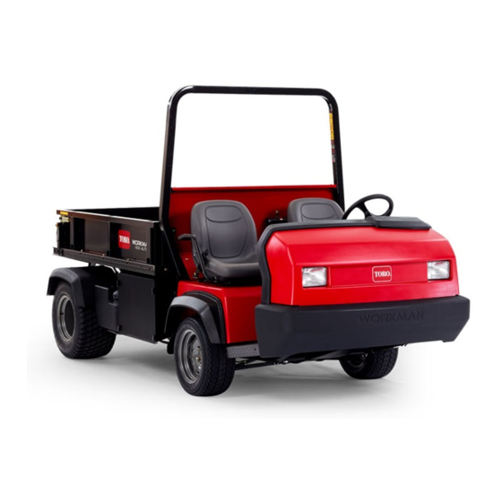
Toro Workman HD 07369 Operator's Manual
Utility vehicle with bed
Hide thumbs
Also See for Workman HD 07369:
- Operator's manual (56 pages) ,
- Operator's manual (56 pages)

Related Manuals for Toro Workman HD 07369


Summary of Contents for Toro Workman HD 07369
- Page 1 Form No. 3382-450 Rev A Workman ® HD Utility Vehicle with Model No. 07369—Serial No. 314000001 and Up *3382-450* A Register at www.Toro.com. Original Instructions (EN)
-
Page 2: Introduction
You are responsible for operating the product properly and safely. Figure 2 You may contact Toro directly at www.Toro.com for product 1. Safety alert symbol and accessory information, help finding a dealer, or to register your product. -
Page 3: Table Of Contents
Contents Servicing the Air Cleaner .........35 Changing the Engine Oil And Filter ......35 Replacing the Spark Plugs ........36 Introduction ..............2 Fuel System Maintenance ...........37 Safety ................4 Replacing the Fuel Filter..........37 Safe Operating Practices........... 4 Inspecting the Fuel Lines and Connections....37 Supervisor’s Responsibilities ........ -
Page 4: Safety
Safety • Always wear substantial shoes. Do not operate the machine while wearing sandals, tennis shoes, or sneakers. Do not wear loose fitting clothing or jewelry which could Safe Operating Practices get caught in moving parts and cause personal injury. •... -
Page 5: Maintenance
– Disengage PTO (if so equipped) and return the hand – Watch out for traffic when near or crossing roads. throttle lever to the Off position (if so equipped). Always yield the right of way to pedestrians and other machines. This machine is not designed for use on –... -
Page 6: Safety And Instructional Decals
The Toro® Company, Commercial Division, Vehicle settings. The maximum engine speed is 3650 RPM. To Engineering Dept., 8111 Lyndale Ave. So., Bloomington, ensure safety and accuracy, have an Authorized Toro Minnesota 55420–1196. USA Distributor check the maximum engine speed with a tachometer. - Page 7 115-7739 1. Falling, crushing hazard, bystanders—no riders on machine. 93-9899 1. Crushing hazard—install the cylinder lock. 105-4215 115-7740 1. Warning—avoid pinch points. 1. Warning—maximum trailer weight is 680 kg (1500 lb), maximum tongue weight is 90 kg (200 lb). 2. Warning—trailer brakes are required when towing greater than 680 kg (1500 lb), maximum trailer weight with trailer brakes is 1591 kg (3500 lb) , maximum tongue weight with trailer brakes is 273 kg (600 lb).
- Page 8 Battery Symbols Some or all of these symbols are on your battery 1. Explosion hazard 6. Keep bystanders a safe distance from the battery. 2. No fire, open flame, or 7. Wear eye protection; smoking. explosive gases can cause blindness and other injuries 3.
- Page 9 115-2282 1. Warning—read the Operator's Manual. 2. Warning—stay away from moving parts, keep all guards and shields in place. 3. Crushing/dismemberment hazard of bystanders—keep bystanders a safe distance from the vehicle, do not carry passengers in the cargo bed, keep arms and legs inside of the vehicle at all times, and use seat belts and handholds. 115-2281 1.
- Page 10 115-7814 115-7746 1. Warning—do not operate this machine unless you are trained. 3. Fire hazard—stop the engine before fueling. 2. Warning—lock the parking brake, stop the engine, and 4. Tipping hazard—slow down and turn gradually, use caution remove the ignition key before leaving the machine. and drive slowly when driving on slopes, do not exceed 32 kph (20 mph), and drive slowly over rough terrain or when carrying a full or heavy load.
- Page 11 106-2377 1. Locked 8. Warning—read the Operator's Manual. 2. Differential lock 9. Entanglement hazard, shaft—keep bystander's a safe distance from the vehicle. 3. Unlocked 10. Retract hydraulics 4. Hydraulic lock 11. Extend hydraulics 5. Engage 12. Transmission—high speed 6. Power take-off (PTO) 13.
-
Page 12: Setup
Setup Loose Parts Use the chart below to verify that all parts have been shipped. Procedure Description Qty. Check the engine oil, the – No parts required transaxle/hydraulic fluid, and the brake fluid levels. Media and Additional Parts Description Qty. Operator's Manual (Machine) Read before operating machine Parts Catalog... -
Page 13: Product Overview
Gear Shift Lever Product Overview Fully press the clutch pedal and move the shift lever (Figure Controls 5) into the desired gear selection. A diagram of the shift pattern is in Figure 4. Note: Determine the left and right sides of the machine from the normal operating position. -
Page 14: Ignition Switch
High is for higher speed driving on level, dry surfaces with light loads. Low is for low speed driving. Use this range when greater than normal power or control is required. For example, steep grades, difficult terrain, heavy loads, slow speed but high engine speed (spraying). -
Page 15: Specifications
Toro distributor for assistance. Check the operation of warning lights as follows: 1. Apply the parking brake. -
Page 16: Attachments/Accessories
The box its capabilities. Contact your Authorized Service Dealer or structure may become damaged if you operate the Distributor or go to www.Toro.com for a list of all approved machine with the box raised. attachments and accessories. -
Page 17: Checking The Engine Oil Level
Lowering the Box Temperature/ viscosity recommendations are as follows: • Above –20 degrees C (0 degrees F)—Use 10W-30. WARNING • Below 0 degrees C (32 degrees F)—Use SAE 5W-30. The weight of the box may be heavy. Hands or Note: SAE 10W-40 and straight weight oils (SAE 30, etc.) other body parts could be crushed. -
Page 18: Adding Fuel
DANGER In certain conditions, gasoline is extremely flammable and highly explosive. A fire or explosion from gasoline can burn you and others and can damage property. • Fill the fuel tank outdoors, in an open area, when the engine is cold. Wipe up any gasoline that spills. -
Page 19: Checking The Transaxle/Hydraulic Fluid Level
WARNING Gasoline is harmful or fatal if swallowed. Long-term exposure to vapors can cause serious injury and illness. • Avoid prolonged breathing of vapors. • Keep face away from nozzle and gas tank or conditioner bottle opening. • Avoid contact with skin; wash off spillage with soap and water. -
Page 20: Checking The Torque Of The Wheel Nuts
Checking the Torque of the Checking the Brake-fluid Level Wheel Nuts Service Interval: Before each use or daily—Check the brake-fluid level. Service Interval: After the first 2 hours Every 1,000 hours/Every 2 years (whichever comes After the first 10 hours first)—Change the brake fluid. -
Page 21: Starting The Engine
2. Fully press the clutch pedal. 3. Move the gear shift lever to 1st gear. 4. Release the clutch pedal smoothly while pressing the accelerator pedal. 5. When the machine gains enough speed, remove your foot from the accelerator pedal, fully press the clutch pedal, move the gear shift lever to the next gear and release the clutch pedal while pressing the accelerator pedal. -
Page 22: Checking The Safety-Interlock System
Verifying the Hydraulic-lift Lever • Check the fluid and engine oil levels regularly and be alert for indications of overheating in any component of the Interlock Switch machine. 1. Sit on the operator’s seat and engage the parking brake. • After starting a cold engine, let it warm up for about 15 2. -
Page 23: Ensuring Proper Speed
Ensuring Proper Braking It is good practice to slow down before you get near an obstacle. This gives you extra time to stop or turn away. Hitting an obstacle can damage the machine and its contents. More important, it can injure you and your passenger. Gross machine weight has a major impact on your ability to stop and/or turn. -
Page 24: Operating On Hills
Operating on Hills Do not carry loads which exceed the load limits described on the machine weight label. WARNING WARNING Tipping or rolling the machine on a hill will cause The bed will lower whenever the dump lever is serious personal injury. pushed down, even when the engine is off. -
Page 25: Using The Differential Lock
Towing the Machine Transporting the Machine In case of an emergency, the machine can be towed for a short distance. However, Toro does not recommend this as For moving the machine long distances, use a trailer. Make a standard procedure. -
Page 26: Using The Hydraulic Control
Several types of tow hitches are available for the Workman, depending on your application. Contact your Authorized Toro Distributor for details. When equipped with a tow hitch bolted onto the rear axle tube, your Workman can tow trailers or attachments with a Gross Trailer Weight (GTW) up to 1587 kg (3500 lb). - Page 27 CAUTION Hydraulic fluid escaping under pressure can have sufficient force to penetrate skin and do serious damage. Care must be used when connecting or disconnecting hydraulic quick couplers. Stop the engine, apply the parking brake, lower the attachment, and place the remote hydraulic valve in the float detent position to relieve hydraulic pressure before connecting or disconnecting quick couplers.
-
Page 28: Maintenance
Maintenance Determine the left and right sides of the machine from the normal operating position. CAUTION Only qualified and authorized personnel shall be permitted to maintain, repair, adjust, or inspect the machine. Avoid fire hazards and have fire protection equipment present in the work area. Do not use an open flame to check level or leakage of fuel, battery electrolyte, or coolant. -
Page 29: Service Interval Chart
Maintenance Service Maintenance Procedure Interval • Torque the front and rear wheel nuts • Inspect opening on filter. • Change the air cleaner paper element. • Check the adjustment of the shift cables. • Check the adjustment of the high–low cable. •... -
Page 30: Operating In Adverse Conditions
Operating in Adverse Conditions Important: If the machine is subjected to any of the conditions listed below, maintenance should be performed twice as frequently: • Desert operation • Cold climate operation below 0° C (32° F) • Trailer towing • Frequent operation on dusty roads •... -
Page 31: Installing The Full Bed
Figure 28 Figure 27 1. Left rear corner of bed 4. Clevis pin 1. Bed mounting plate 4. Lynch pin 2. Machine frame channel 5. Lynch pin 2. Cylinder rod end 5. Rear slots (Full bed) 3. Pivot plate 3. Clevis pin 6. -
Page 32: Raising The Machine
Note: The rear slots are for a full bed installation and front slots are for a 2/3 bed installation. Note: The engine may need to be started to extend or retract the cylinders for alignment with the holes. Keep fingers out! Note: The unused slot can be plugged with a bolt and nut to prevent assembly errors. -
Page 33: Installing The Hood
Lubrication Greasing Bearings and Bushings Service Interval: Every 100 hours (Lubricate more frequently in heavy duty applications) The machine has grease fittings that must be lubricated regularly with No. 2 General Purpose Lithium Base Grease. The grease fitting locations and quantities are as follows: •... - Page 34 Figure 34 Figure 35 Figure 36...
-
Page 35: Engine Maintenance
Engine Maintenance Inspecting the Carbon Canister Air Filter Service Interval: After the first 50 hours Every 200 hours 1. Locate the air filter on the bottom of the carbon canister (Figure 37). Figure 38 1. Knob and O-ring 5. Breather seal 2. -
Page 36: Replacing The Spark Plugs
Replacing the Spark Plugs 1. Raise the bed (if so equipped) and place the safety support on the extended lift cylinder to hold up the Service Interval: Every 800 hours bed. 2. Remove the drain plug and let oil flow into a drain pan The spark plugs usually last a long time;... -
Page 37: Fuel System Maintenance
Fuel System Electrical System Maintenance Maintenance Replacing the Fuel Filter Servicing the Fuses Service Interval: Every 400 hours The fuses for the machine’s electrical system are located under the center of the dash panel (Figure 42 & Figure 43). 1. Raise the bed (if so equipped) and place the safety support on the extended lift cylinder to hold up the bed. -
Page 38: Jump Starting The Machine
Jump Starting the Machine Note: Do not connect the other end of the jumper cable to the negative post of the discharged battery. Connect it to the engine or frame. Do not connect the WARNING jumper cable to the fuel system. Jump starting can be dangerous. -
Page 39: Drive System Maintenance
Drive System • If corrosion occurs at terminals, remove the battery cover, disconnect the cables (negative (–) cable first), and Maintenance scrape the clamps and terminals separately. Reconnect the cables (positive (+) cable first) and coat the terminals with petroleum jelly. Adjusting the Shift Cables •... -
Page 40: Inspecting The Tires
2. Loosen the jam nuts securing the differential lock cable to the bracket on the transaxle (Figure 47). Figure 49 1. Over inflated tire Checking the Front-wheel Alignment Service Interval: Every 400 hours/Yearly (whichever comes first) Figure 47 1. Make sure the tires are facing straight ahead. 1. -
Page 41: Cooling System Maintenance
Cooling System Maintenance Removing Debris from the Engine Cooling System Service Interval: Every 100 hours (Clean more frequently in dirty conditions.) To ensure proper cooling, clean the blower housing and other cooling shrouds and clean the cooling fins and external surfaces. -
Page 42: Brake Maintenance
Brake Maintenance Adjusting the Brake Pedal Service Interval: Every 200 hours Adjusting the Parking Brake Note: Remove the font hoot to ease the adjustment procedure. Service Interval: After the first 10 hours 1. Remove the cotter pin and clevis pin securing the Every 200 hours master cylinder yoke to the brake pedal pivot (Figure 1. -
Page 43: Belt Maintenance
Belt Maintenance Controls System Maintenance Checking the Pump Belt Tension Adjusting the Clutch Pedal Service Interval: After the first 8 hours Service Interval: Every 200 hours Every 200 hours Note: You can adjust the clutch pedal cable at the bell Check the pump belt for wear, cracking, or improper tension. -
Page 44: Adjusting The Accelerator
Note: Force is applied so the clutch release bearing lightly contacts the pressure plate fingers. 4. Tighten the jam nuts after the adjustment has been attained. 5. Recheck the 9.5 ± 0.3 cm (3.75 ± 0.12 inch) dimension after the jam nuts have been tightened to ensure proper adjustment. -
Page 45: Adjusting The Choke
Hydraulic System Maintenance Changing the Hydraulic Fluid and Cleaning the Strainer Service Interval: Every 800 hours 1. Position the machine on a level surface, stop the engine, engage the parking brake, and remove the key from the ignition switch. Figure 61 2. -
Page 46: Replacing The Hydraulic Filter
Figure 64 1. Hydraulic filter 3. Lubricate the gasket on the new filter. 4. Ensure that the filter mounting area is clean. Screw the Figure 63 filter on until the gasket contacts the mounting plate. 1. Hydraulic strainer Then tighten the filter one-half turn. 5. - Page 47 make sure the machine used to jump the hydraulic system uses an equivalent fluid. 2. On both machines, disconnect the 2 quick coupler hoses from the hoses secured to the coupler bracket (Figure 65). Figure 67 1. Jumper hoses 7. Keep all bystanders away from the machines. 8.
-
Page 48: Cleaning
Cleaning Washing the Machine The machine should be washed as needed. Use water alone or with a mild detergent. A rag may be used when washing the machine, however the hood will loose some of its luster. Important: Do not use power washing equipment to wash the machine. -
Page 49: Storage
Storage 11. Use the starter to crank the engine and distribute the oil inside the cylinder. 1. Position the machine on a level surface, set the parking 12. Install the spark plugs and tighten to recommended brake, stop the engine, and remove the ignition key. torque;... -
Page 50: Troubleshooting
Troubleshooting Problem Possible Cause Corrective Action The engine does not start, starts hard, or 1. The hydraulic lever is locked in forward 1. Move the hydraulic lever out of forward fails to keep running. position position. 2. The fuel tank is empty. 2. - Page 51 Notes:...
- Page 52 Countries Other than the United States or Canada Customers who have purchased Toro products exported from the United States or Canada should contact their Toro Distributor (Dealer) to obtain guarantee policies for your country, province, or state. If for any reason you are dissatisfied with your Distributor's service or have difficulty obtaining guarantee information, contact the Toro importer.