
Related Manuals for D-Link DXS-1210 Series


Summary of Contents for D-Link DXS-1210 Series
- Page 1 D X S - 1 2 1 0 S e r i e s L 2 1 0 G i g a b i t E t h e r n e t S w i t c h S e r i e s V e r .
-
Page 3: Table Of Contents
Table of Contents D-Link DXS-1210 Series User Manual Table of Contents Table of Contents ............................. i About This Guide ............................. 1 Terms/Usage ..............................1 Copyright and Trademarks ..........................1 Product Introduction ........................... 2 DXS-1210-10TS ............................. 3 Front Panel ..............................3 Rear Panel .............................. - Page 4 Management > Telnet/Web ........................33 Management > Session Timeout ......................33 Management > D-Link Discover Protocol Settings................... 34 L2 Features > FDB > Static FDB > Unicast Static FDB ................34 L2 Features > FDB > Static FDB > Multicast Static FDB ................. 35 L2 Features >...
- Page 5 Table of Contents D-Link DXS-1210 Series User Manual L2 Features > STP > MST Configuration Identification................41 L2 Features > STP > STP Instance ......................42 L2 Features > STP > MSTP Port Information ..................42 L2 Features > Loopback Detection ......................42 L2 Features >...
- Page 6 Table of Contents D-Link DXS-1210 Series User Manual Security > Trusted Host ..........................91 Security > Traffic Segmentation Settings ....................92 Security > Storm Control Settings ......................92 Security > DoS Attack Prevention Settings ....................93 Security > SSL > SSL Global Setting ....................... 94 Security >...
-
Page 7: About This Guide
Reproduction in any manner whatever without the written permission of D-Link Corporation is strictly forbidden. Trademarks used in this text: D-Link and the D-LINK logo are trademarks of D-Link Corporation; Microsoft and Windows are registered trademarks of Microsoft Corporation. Other trademarks and trade names may be used in this document to refer to either the entities claiming the marks and names or their products. -
Page 8: Product Introduction
D-Link Green Technology includes a number of innovations to reduce energy consumption on DXS-1210 series such as reducing power when a port does not have a device attached, or adjusting the power usage according to the length of Ethernet cable connected to it. -
Page 9: Dxs-1210-10Ts
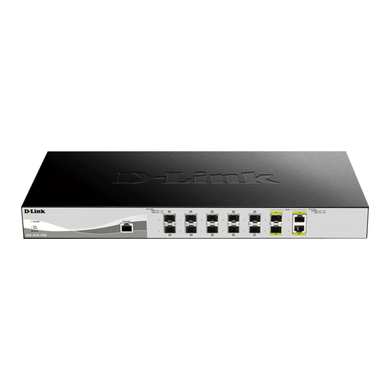
1 Product Introduction D-Link DXS-1210 Series User Manual DXS-1210-10TS 8-Port 10GBASE-T and 2-Port SFP + Fiber port L2 10 Gigabit Ethernet Switch. Front Panel Figure 1.1 – DXS-1210-10TS Front Panel Power LED : The Power LED lights up when the Switch is connected to a power source. -
Page 10: Rear Panel
1 Product Introduction D-Link DXS-1210 Series User Manual Reset: By pressing the Reset button, the Switch will change back to the default configuration and all changes will be lost. Rear Panel Figure 1.4 – DXS-1210-12TC Rear Panel Power: Connect the AC power cord to this port. -
Page 11: Hardware Installation
2 Hardware Installation D-Link DXS-1210 Series User Manual Hardware Installation This chapter provides unpacking and installation information for the D-Link DXS-1210 Series Switch. Safety Cautions To reduce the risk of bodily injury, electrical shock, fire,and damage to the equipment, observe the following precautions: •... -
Page 12: Step 1: Unpacking
D-Link reseller for replacement. One D-Link DXS-1210 Series switch One Multilingual Getting Started Guide User Guide CD with DNA (D-Link Network Assistant) Program Power Cord and Power Cord Retainer Rack-mount kit and Rubber Feet If any item is found missing or damaged, please contact the local reseller for replacement. -
Page 13: Step 3 - Plugging In The Ac Power Cord
2 Hardware Installation D-Link DXS-1210 Series User Manual Figure 2.3 – Mount the Switch in the rack or chassis Step 3 – Plugging in the AC Power Cord The Switch can now be connected to the AC power. Connect the AC power cord to the rear of the switch and to an electrical outlet (preferably one that is grounded and surge protected). -
Page 14: Getting Started
This chapter introduces the management interface of D-Link DXS-1210 Series Switch. Management Options The D-Link DXS-1210 Series. Switch can be managed through any port by using the Web-based Management, or through any PC using CLI commands. Each switch must be assigned its own IP Address, which is used for communication with the Web-Based Management or a SNMP network manager. -
Page 15: Smart Wizard
English. Figure 3.3 – Login Dialog Box Smart Wizard After a successful login, the Smart Wizard will guide you through essential settings of the D-Link DXS-1210 Series Switch. Please refer to the Smart Wizard Configuration section for details. Web-based Management By clicking the Exit button in the Smart Wizard, you will enter the Web-based Management interface. -
Page 16: Configuration
4 Configuration D-Link DXS-1210 Series User Manual Configuration The features and functions of the D-Link DXS-1210 Series Switch can be configured for optimum use through the Web-based Management Utility. Smart Wizard Configuration After a successful login, the Smart Wizard will guide you through essential settings of the D-Link DXS-1210 Series Switch. -
Page 17: User Accounts Settings
4 Configuration D-Link DXS-1210 Series User Manual Figure 4.2 – SNMP Settings in Smart Wizard User Accounts Settings The User Accounts Settings page allows you to quickly specify the user account function. Enter the User Name, Privilege, Password Type and Password. Click Apply & Save to save the configuration. -
Page 18: Tool Bar > Save Menu
Click the D-Link logo at the upper-left corner of the screen to be redirected to the local D-Link website. Tool Bar > Save Menu The Save Menu provides Save Configuration and Save Log functions. -
Page 19: Tool Bar > Tool Menu
4 Configuration D-Link DXS-1210 Series User Manual Figure 4.6 – Save Configuration Destination: Select the destination to save the configuration to. Startup-config: Check the box to enable the startup configuration function. Click the Apply button to save your settings. Tool Bar > Tool Menu The Tool Menu offers global function controls such as Reset, Reboot Device, Configuration Backup and Restore, Firmware Backup and Upgrade. -
Page 20: Firmware Upgrade & Backup > Firmware Upgrade From Tftp
4 Configuration D-Link DXS-1210 Series User Manual Figure 4.10 – Tool Menu > Firmware Upgrade & Backup > Firmware Upgrade from HTTP Note: The Switch will reboot after restoring the firmware, and all current configuration will be lost. Firmware Upgrade & Backup > Firmware Upgrade from TFTP Upgrade firmware by using TFTP. -
Page 21: Configuration Upgrade & Backup > Configuration Backup To Http
4 Configuration D-Link DXS-1210 Series User Manual Figure 4.15 – Tool Menu > Configuration Upgrade & Backup > Configuration Restore from TFTP Configuration Upgrade & Backup > Configuration Backup to HTTP To save the current configuration to a file, click Backup. -
Page 22: Ping
Tool Bar > Online Help The Online Help provides two ways of online support: D-link Support Site will lead you to the D-Link website where you can find online resources such as updated firmware; User Guide can offer an immediate reference for the feature definition or configuration guide. - Page 23 4 Configuration D-Link DXS-1210 Series User Manual Figure 4.24 – User Guide Micro Site...
-
Page 24: Function Tree
4 Configuration D-Link DXS-1210 Series User Manual Function Tree All configuration options on the switch are accessed through the Setup menu on the left side of the main window. Click on the setup item that you want to configure. The following sections provide more detailed description of each feature and function. -
Page 25: System > Port Configuration > Port Settings
4 Configuration D-Link DXS-1210 Series User Manual Figure 4.27 – System > System Information System > Port Configuration > Port Settings In the Port Settings page, the status of all ports can be monitored and adjusted for optimum configuration. Figure 4.28 – System > Port Configuration > Port Settings From Port / To Port: Select the appropriate port range to be configured. -
Page 26: System > Port Configuration > Error Disable Settings
4 Configuration D-Link DXS-1210 Series User Manual Figure 4.29 – System > Port Configuration > Port Status System > Port Configuration > Error Disable Settings The Error Disable Settings page allows you to configure the sending of SNMP notifications for error disable state. -
Page 27: System > Port Configuration > Jumbo Frame
4 Configuration D-Link DXS-1210 Series User Manual System > Port Configuration > Jumbo Frame The Jumbo Frame page allows you to view and configure the Jumbo Frame size and settings. Jumbo frames are Ethernet frames with more than 1,518 bytes of payload. The Switch supports jumbo frames with a maximum frame size of up to 9216 bytes. -
Page 28: System > System Log > System Log
4 Configuration D-Link DXS-1210 Series User Manual Figure 4.33 – System > System Log > System Log Server Settings IP Address: Select and enter the IPv4 address or IPv6 Address. UDP Port (514 or 1024-65535): Enter the system log server’s UDP port number. This value must be 514 or between 1024 and 65535. - Page 29 4 Configuration D-Link DXS-1210 Series User Manual Figure 4.36 – System > Time and SNTP > Time Zone Settings Summer Time State: Select Summer Time State setting. Options to choose from are Disabled, Recurring Setting, and Date Setting. Time Zone Offset: Select the local time zone’s offset from Coordinated Universal Time (UTC).
-
Page 30: System > Time And Sntp > Sntp Settings
4 Configuration D-Link DXS-1210 Series User Manual System > Time and SNTP > SNTP Settings The SNTP Settings page allows you to configure the time settings for the Switch. Figure 4.37 – System > Time and SNTP > SNTP Settings SNTP Global Settings: SNTP State: Select to enable or disable the SNTP state. -
Page 31: Management > User Accounts Settings
4 Configuration D-Link DXS-1210 Series User Manual Management > User Accounts Settings The User Accounts Settings page allows you to create and configure user accounts. Active user account sessions can be viewed. By default, there is no user account created on the Switch. -
Page 32: Management > Snmp > Snmp Global Settings
4 Configuration D-Link DXS-1210 Series User Manual Management > SNMP > SNMP Global Settings Simple Network Management Protocol (SNMP) is an OSI Layer 7 (Application Layer) protocol designed specifically for managing and monitoring network devices. SNMP enables network management stations to read and modify the settings of gateways, routers, switches, and other network devices. -
Page 33: Management > Snmp > Snmp View Table Settings
4 Configuration D-Link DXS-1210 Series User Manual Management > SNMP > SNMP View Table Settings The SNMP View page allows you to maintain SNMP views to community strings that define the MIB objects which can be accessed by a remote SNMP manager. -
Page 34: Management > Snmp > Snmp Group Table Settings
4 Configuration D-Link DXS-1210 Series User Manual string to access to the SNMP agent. Click Add to a new entry based on the information entered or Delete to remove the specified entry. Management > SNMP > SNMP Group Table Settings The SNMP Group page allows you to assign SNMP Users into SNMP Groups. -
Page 35: Management > Snmp > Snmp User Table Settings
4 Configuration D-Link DXS-1210 Series User Manual Figure 4.46 – Management > SNMP > SNMP Engine ID Local Settings Management > SNMP > SNMP User Table Settings The SNMP User Table Settings page allows you to maintain the SNMP user table for the use of SNMPv3. -
Page 36: Management > Snmp > Snmp Host Table Settings
4 Configuration D-Link DXS-1210 Series User Manual Click Add to create a new SNMP user account or click Delete to remove any existing data. Management > SNMP > SNMP Host Table Settings The SNMP Host Table Settings page allows you to configure the SNMP trap recipients. -
Page 37: Management > Rmon > Rmon History Settings
4 Configuration D-Link DXS-1210 Series User Manual Figure 4.50 – Management > RMON > RMON Statistics Settings The RMON Ethernet Statistics Configuration contains the following fields: Port: Select the port from which the RMON information was taken. Index (1 - 65535): Indicates the RMON Ethernet Statistics entry number. -
Page 38: Management > Rmon > Rmon Event Settings
4 Configuration D-Link DXS-1210 Series User Manual Figure 4.52 – Management > RMON > RMON Alarm Settings The configuration contains the following fields: Index (1 - 65535): Enter a specific alarm. Variable: Select the selected MIB variable value. Rising Threshold (0 ~ 2^31-1): Displays the rising counter value that triggers the rising threshold alarm. -
Page 39: Management > Telnet/Web
4 Configuration D-Link DXS-1210 Series User Manual Type: Select the event type. The possible values are: None – Indicates that no event occurred. Log – Indicates that the event is a log entry. SNMP Trap – Indicates that the event is a trap. -
Page 40: Management > D-Link Discover Protocol Settings
4 Configuration D-Link DXS-1210 Series User Manual Management > D-Link Discover Protocol Settings The D-Link Discover Protocol Settings page allows you to configure and display D-Link Discovery Protocol (DDP). Figure 4.56 – Management > D-Link Discover Protocol Settings D-Link Discovery Protocol State: Enter the enable or disable the D-Link Discovery Protocol state. -
Page 41: L2 Features > Fdb > Static Fdb > Multicast Static Fdb
4 Configuration D-Link DXS-1210 Series User Manual Enter a page number and click the Go button to navigate to a specific page when multiple pages exist. L2 Features > FDB > Static FDB > Multicast Static FDB The Multicast Static FDB page allows you to view and configure the static multicast forwarding settings on the Switch. -
Page 42: L2 Features > Fdb > Mac Address Table
4 Configuration D-Link DXS-1210 Series User Manual Figure 4.60 – L2 Features > FDB > MAC Address Table Settings – MAC Address Learning From Port / To Port: Enter the range of ports that will be used for this configuration. -
Page 43: L2 Features > Asymmetric Vlan
4 Configuration D-Link DXS-1210 Series User Manual Figure 4.62 – L2 Features > 802.1Q VLAN 802.1Q VLAN: VID List: Enter the VLAN ID list that will be created. Click the Apply button to save your settings. Click the Delete button to remove the specific entry. -
Page 44: L2 Features > Stp > Stp Global Settings
4 Configuration D-Link DXS-1210 Series User Manual After clicking the VLAN Detail button, the following page will appear: Figure 4.65 – L2 Features > VLAN Interface – VLAN Detail After clicking the Edit button, the following window will appear. This is a dynamic window that will change when a different VLAN Mode is selected. - Page 45 4 Configuration D-Link DXS-1210 Series User Manual each link between bridges is sensitive to the status of the link. Ultimately this difference results in faster detection of failed links, and thus faster topology adjustment. By default Multiple Spanning Tree is enabled. It will tag BPDU packets to receiving devices and distinguish spanning tree instances, spanning tree regions and the VLANs associated with them.
-
Page 46: L2 Features > Stp > Stp Port Settings
4 Configuration D-Link DXS-1210 Series User Manual Each switch on the hop count will reduce the hop count by one until the value reaches zero. The Switch will then discard the BDPU packet and the information held for the port will age out. -
Page 47: L2 Features > Stp > Mst Configuration Identification
4 Configuration D-Link DXS-1210 Series User Manual considered to have a Shared connection .The port cannot transit into the forwarding state rapidly by setting the link type to Shared. By default this option is Auto. Port Fast: Select the port fast option. The options to choose from are Network, Disabled, and Edge. In the Network mode the port will remain in the non-port-fast state for three seconds. -
Page 48: L2 Features > Stp > Stp Instance
4 Configuration D-Link DXS-1210 Series User Manual Instance ID Settings: Instance ID (1 - 64): Enter the MSTI ID associated with the VID List. The possible field range is 1-64. Action: The possible values are: Add VID - Indicates that the edit type is add. -
Page 49: L2 Features > Link Aggregation
4 Configuration D-Link DXS-1210 Series User Manual Figure 4.72 – L2 Features > Loopback Detection Settings Loopback Detection State: Enable or disable loopback detection. The default is disabled. Mode: Select either Port-based or VLAN-based. Enabled VLAN ID List: Enter the VLAN ID for loop detection. This only takes effect when the VLAN-based is selected in the Mode drop-down list. -
Page 50: L2 Features > L2 Multicast Control > Igmp Snooping > Igmp Snooping Settings
IGMP snooping can help reduce cluttered traffic on the LAN. With IGMP snooping enabled globally, the DXS-1210 Series Switch will forward multicast traffic only to connections that have group members attached. The settings of IGMP snooping is set by each VLAN individually. - Page 51 4 Configuration D-Link DXS-1210 Series User Manual Click the Edit button to re-configure the specific entry. Enter a page number and click the Go button to navigate to a specific page when multiple pages exist. After clicking the Show Detail button, the following window will appear: Figure 4.75 –...
-
Page 52: L2 Features > L2 Multicast Control > Igmp Snooping > Igmp Snooping Groups Settings
4 Configuration D-Link DXS-1210 Series User Manual Robustness Value (1-7): Enter the robustness variable used in IGMP snooping. Last Member Query Interval (1-25): Enter the interval at which the IGMP snooping querier sends IGMP group-specific or group-source-specific query messages. Click the Apply button to save your settings. -
Page 53: L2 Features > L2 Multicast Control > Igmp Snooping > Igmp Snooping Statistics Settings
4 Configuration D-Link DXS-1210 Series User Manual Figure 4.78 – L2 Features > L2 Multicast Control > IGMP Snooping > IGMP Snooping Mrouter Settings VID (1-4094): Enter the VLAN ID and the range is between 1 and 4094. Configuration: Select the port configuration type. -
Page 54: L2 Features > L2 Multicast Control > Mld Snooping > Mld Snooping Setting
4 Configuration D-Link DXS-1210 Series User Manual Click the Find button to locate a specific entry based on the information entered. Click the Find All button to view all the entries. L2 Features > L2 Multicast Control > MLD Snooping > MLD Snooping Setting The MLD Snooping Settings page allows you to configure the MLD snooping settings. - Page 55 4 Configuration D-Link DXS-1210 Series User Manual Figure 4.81 – L2 Features > L2 Multicast Control > MLD Snooping > MLD Snooping Setting – Show Detail The window displays the detail information about MLD snooping VLAN. Click the Modify button to edit the information in the following window.
-
Page 56: L2 Features > L2 Multicast Control > Mld Snooping > Mld Snooping Groups Setting
4 Configuration D-Link DXS-1210 Series User Manual Click the Apply button to save your settings. L2 Features > L2 Multicast Control > MLD Snooping > MLD Snooping Groups Setting The MLD Snooping Groups Settings page allows you to configure and view the MLD snooping static group, and view MLD snooping group. -
Page 57: L2 Features > L2 Multicast Control > Mld Snooping > Mld Snooping Statistics Settings
4 Configuration D-Link DXS-1210 Series User Manual Figure 4.84 – L2 Features > L2 Multicast Control > MLD Snooping > MLD Snooping Mrouter Settings VID (1-4094): Enter the VLAN ID. Configuration: Select the port configuration. Available options are Port and Forbidden Port. -
Page 58: L2 Features > Lldp > Lldp Global Settings
4 Configuration D-Link DXS-1210 Series User Manual Figure 4.86 – L2 Features > L2 Multicast Control > Multicast Filtering VID List: Enter the VLAN ID. Multicast Filter Mode: Select the multicast filter mode. Options to choose from are Forward Unregistered, Forward All, and Filter Unregistered. -
Page 59: L2 Features > Lldp > Lldp Port Settings
4 Configuration D-Link DXS-1210 Series User Manual through ports. For the receiving of LLDP packets, the switch will learn the information from the LLDP packets advertised from the neighbor in the neighbor table. Click Apply to make the change effective. -
Page 60: L2 Features > Lldp > Lldp Management Address List
4 Configuration D-Link DXS-1210 Series User Manual and IPv6. Action: Select to remove or add the action field. Address: Enter the IP address to be sent. Click Apply to accept the changes made. L2 Features > LLDP > LLDP Management Address List The LLDP Management Address List page displays the detailed management address information for the entry. -
Page 61: L2 Features > Lldp > Lldp Dot1 Tlvs Settings
4 Configuration D-Link DXS-1210 Series User Manual L2 Features > LLDP > LLDP Dot1 TLVs Settings This LLDP Dot1 TLVs Settings page allows you to configure an individual port or group of ports to exclude one or more of the IEEE 802.1 organizational port VLAN ID TLV data types from outbound LLDP advertisements. -
Page 62: L2 Features > Lldp > Lldp-Med Port Settings
4 Configuration D-Link DXS-1210 Series User Manual MAC/PHY Configuration/Status: Select whether the MAC/PHY Configuration Status is enabled on the port. The possible field values are: Enabled – Enables the MAC/PHY Configuration Status on the port. Disabled – Disables the MAC/PHY Configuration Status on the port. -
Page 63: L2 Features > Lldp > Lldp Local Port Information
4 Configuration D-Link DXS-1210 Series User Manual Figure 4.94 – L2 Features > LLDP > LLDP Statistics Information The following information can be viewed: LLDP Statistics Information: Displays the counters that refer to the whole switch. Last Change Time – Displays the time for when the last change entry was last deleted or added. It is also displays the time elapsed since last change was detected. -
Page 64: L2 Features > Lldp > Lldp Neighbor Port Information
4 Configuration D-Link DXS-1210 Series User Manual Figure 4.95 – L2 Features > LLDP > LLDP Local Port Information Port: Displays the port number. Port ID Subtype: Displays the port ID subtype. Port ID: Displays the port ID (Unit number/Port number). -
Page 65: L3 Features > Arp > Arp Aging Time
4 Configuration D-Link DXS-1210 Series User Manual Click the Clear button to remove the specified port of LLDP neighbor port or click Clear All button to remove all LLDP neighbor ports. L3 Features > ARP > ARP Aging Time The ARP Aging Time page allows you to view and configure the ARP aging time settings. -
Page 66: L3 Features > Ipv4 Interface
4 Configuration D-Link DXS-1210 Series User Manual Figure 4.100 – L3 Features > ARP > ARP Table Interface VLAN (1-4094): Select and enter the interface’s VLAN ID. IP address: Select and enter the IP address to be displayed. Mask: Enter the mask address for the specified IP address. -
Page 67: L3 Features > Ipv4 Default Route
4 Configuration D-Link DXS-1210 Series User Manual Click the Back button to return to the previous window. State: Select to enable or disable the IPv4 interface’s global state. Click the Apply button to save your settings. IP Settings: Get IP From: Select the IP from option. The values are Static and DHCP. When the Static option is selected, users can enter the IPv4 address of this interface manually in the fields provided. - Page 68 4 Configuration D-Link DXS-1210 Series User Manual Figure 4.105 – L3 Features > IPv6 Interface Interface VLAN (1-4094): Enter the VLAN ID of IP interface. Click Apply for the settings to take effect. Click the Find button to display the specific entry.
-
Page 69: L3 Features > Ipv6 Neighbor
4 Configuration D-Link DXS-1210 Series User Manual Figure 4.108 – L3 Features > IPv6 Interface – DHCPv6 Client Click the Restart button to restart the DHCPv6 client. Client State: Select to enable or disable the DHCPv6 client state. Click the Apply button to save your settings. -
Page 70: Qos > Port Scheduler Method
4 Configuration D-Link DXS-1210 Series User Manual Figure 4.111 – QoS > Port Default CoS From Port / To Port: Select the range of ports to be configured. Default CoS: Select the default CoS option for the specified ports. The values are from 0 to 7. Click the Override check box to apply the port's default CoS to all packets (tagged or untagged) received by the port. -
Page 71: Qos > Cos To Queue Mapping
4 Configuration D-Link DXS-1210 Series User Manual Figure 4.113 – QoS > Queue Settings From Port / To Port: Select the range of ports to be configured. Queue ID: Select the queue id value. The range is between 0 and 7. -
Page 72: Qos > Queue Rate Limiting
4 Configuration D-Link DXS-1210 Series User Manual Figure 4.115 – QoS > Port Rate Limiting From Port / To Port: Select the range of ports to be configured. Direction: Select the direction. Available options are Input and Output. When Input is selected, the rate limit for ingress packets is configured. -
Page 73: Qos > Port Trust State
4 Configuration D-Link DXS-1210 Series User Manual Figure 4.116 – QoS > Queue Rate Limiting From Port / To Port: Select the range of ports to be configured. Queue ID: Select the queue ID for the specified ports. The value is between 0 and 7. -
Page 74: Qos > Dscp Cos Mapping
4 Configuration D-Link DXS-1210 Series User Manual QoS > DSCP CoS Mapping The DSCP CoS Mapping page allows you to view and configure the DSCP CoS mapping settings. Figure 4.118 – QoS > DSCP CoS Mapping From Port / To Port: Select the range of ports to be configured. - Page 75 4 Configuration D-Link DXS-1210 Series User Manual Figure 4.120 – ACL > ACL Configuration Wizard – Packet Type MAC: Select to create a MAC ACL. IPv4: Select to create an IPv4 ACL. IPv6: Select to create an IPv6 ACL. Click the Back button to return to the previous window.
- Page 76 4 Configuration D-Link DXS-1210 Series User Manual Ethernet Type (0x600-0xFFFF): Enter the Ethernet type hexadecimal value. The value is between 0x600 and 0xFFFF. When any Ethernet type profile is selected in the Specify Ethernet Type drop-down list, the appropriate hexadecimal value will automatically be entered.
- Page 77 4 Configuration D-Link DXS-1210 Series User Manual Figure 4.123 – ACL > ACL Configuration Wizard – Create IPv4 ACL-TCP Source: Select the source information. The values are Any, Host and IP. Destination: Select the destination information. The values are Any, Host and IP.
- Page 78 4 Configuration D-Link DXS-1210 Series User Manual Figure 4.124 – ACL > ACL Configuration Wizard – Create IPv4 ACL-UDP Source: Select the source information. The values are Any, Host and IP. Destination: Select the destination information. The values are Any, Host and IP.
- Page 79 4 Configuration D-Link DXS-1210 Series User Manual Figure 4.125 – ACL > ACL Configuration Wizard – Create IPv4 ACL-ICMP Source: Select the source information. The values are Any, Host and IP. Destination: Select the destination information. The values are Any, Host and IP.
- Page 80 4 Configuration D-Link DXS-1210 Series User Manual Figure 4.126 – ACL > ACL Configuration Wizard – Create IPv4 ACL-EIGRP Source: Select the source information. The values are Any, Host and IP. Destination: Select the destination information. The values are Any, Host and IP.
- Page 81 4 Configuration D-Link DXS-1210 Series User Manual Source: Select the source information. The values are Any, Host and IP. Destination: Select the destination information. The values are Any, Host and IP. IP Precedence: Select the IP precedence value. Options to choose from are 0 (routine), 1 (priority), 2, (immediate), 3 (flash), 4 (flash-override), 5 (critical), 6 (internet), and 7 (network).
- Page 82 4 Configuration D-Link DXS-1210 Series User Manual Figure 4.129 – ACL > ACL Configuration Wizard – Create IPv4 ACL-IGMP Fragments: Select the Fragments option to include packet fragment filtering. Source: Select the source information. The values are Any, Host and IP.
- Page 83 4 Configuration D-Link DXS-1210 Series User Manual Fragments: Select the Fragments option to include packet fragment filtering. Source: Select the source information. The values are Any, Host and IP. Destination: Select the destination information. The values are Any, Host and IP.
- Page 84 4 Configuration D-Link DXS-1210 Series User Manual Figure 4.132 – ACL > ACL Configuration Wizard – Create IPv4 ACL-VRRP Fragments: Select the Fragments option to include packet fragment filtering. Source: Select the source information. The values are Any, Host and IP.
- Page 85 4 Configuration D-Link DXS-1210 Series User Manual Fragments: Select the Fragments option to include packet fragment filtering. Source: Select the source information. The values are Any, Host and IP. Destination: Select the destination information. The values are Any, Host and IP.
- Page 86 4 Configuration D-Link DXS-1210 Series User Manual Figure 4.135 – ACL > ACL Configuration Wizard – Create IPv4 ACL-Protocol ID Fragments: Select the Fragments option to include packet fragment filtering. Source: Select the source information. The values are Any, Host and IP.
- Page 87 4 Configuration D-Link DXS-1210 Series User Manual Fragments: Select the Fragments option to include packet fragment filtering. Source: Select the source information. The values are Any, Host and IP. Destination: Select the destination information. The values are Any, Host and IP.
- Page 88 4 Configuration D-Link DXS-1210 Series User Manual Figure 4.138 – ACL > ACL Configuration Wizard – Create IPv6 ACL-UDP Source Port: Select the source port value. Destination Port: Select the destination port value. Source: Select the source information. The values are Any, Host and IP.
- Page 89 4 Configuration D-Link DXS-1210 Series User Manual Figure 4.139– ACL > ACL Configuration Wizard – Create IPv6 ACL-ICMP Source: Select the source information. The values are Any, Host and IP. Destination: Select the destination information. The values are Any, Host and IP.
- Page 90 4 Configuration D-Link DXS-1210 Series User Manual Figure 4.140 – ACL > ACL Configuration Wizard – Create IPv6 ACL-Protocol ID Source: Select the source information. The values are Any, Host and IP. Destination: Select the destination information. The values are Any, Host and IP.
- Page 91 4 Configuration D-Link DXS-1210 Series User Manual Figure 4.142 – ACL > ACL Configuration Wizard – Create IPv6 ACL-PCP Source: Select the source information. The values are Any, Host and IP. Destination: Select the destination information. The values are Any, Host and IP.
- Page 92 4 Configuration D-Link DXS-1210 Series User Manual DSCP (0-63): Enter the DSCP value. And the range is between 0 and 63. Flow Label (0-1048575): Enter the flow label value. This value must be between 0 and 1048575. Action: Select the action for the rule. The values are Permit and Deny.
-
Page 93: Acl > Acl Access List
4 Configuration D-Link DXS-1210 Series User Manual ACL > ACL Access List The ACL Access List page allows you to view and configure the ACL access list settings. Figure 4.146 – ACL > ACL Access List ACL Type: Select the ACL profile type to find. Options to choose from are All, IP ACL, IPv6 ACL, MAC ACL, and Expert ACL. -
Page 94: Security > Port Security > Port Security Global Settings
4 Configuration D-Link DXS-1210 Series User Manual After clicking the Please Select button, the following page will appear. Figure 4.148 – ACL > ACL Interface Access Group - Select Security > Port Security > Port Security Global Settings The Port Security Global Settings page allows you to view and configure the port security global settings. -
Page 95: Security > Port Security > Port Security Port Settings
4 Configuration D-Link DXS-1210 Series User Manual Security > Port Security > Port Security Port Settings The Port Security Port Settings page allows you to view and configure the port security port settings of the Switch. Figure 4.150 – Security > Port Security > Port Security Port Settings From Port / To Port: Select the range of ports to be configured. -
Page 96: Security > Dhcp Server Screening > Dhcp Server Screening Global Settings
4 Configuration D-Link DXS-1210 Series User Manual VID (1-4094): Enter the VLAN ID. The range is between 1 and 4094. Click the Add button to add a new entry based on the information entered. Click the Delete button to remove a new entry based on the information entered. -
Page 97: Security > Safeguard Engine
D-Link’s Safeguard Engine is a robust and innovative technology that automatically throttles the impact of packet flooding into the switch's CPU. This function helps to protect the DXS-1210 Series Switch from being interrupted by malicious viruses or worm attacks. This option is enabled by default. -
Page 98: Security > Traffic Segmentation Settings
4 Configuration D-Link DXS-1210 Series User Manual Type: Specify the trusted host type. The options are Telnet, Ping, HTTP and HTTPS. Click the Apply button to save your settings. Security > Traffic Segmentation Settings This feature provides administrators to limit traffic flow from a single port to a group of ports on a single Switch. -
Page 99: Security > Dos Attack Prevention Settings
4 Configuration D-Link DXS-1210 Series User Manual Trap State: Select the storm control trap state. The options are None, Storm Occur, Storm Clear, and Both. When None is selected, no traps will be sent. When Storm Occur is selected, a trap notification will be sent when a storm event is detected. -
Page 100: Security > Ssl > Ssl Global Setting
4 Configuration D-Link DXS-1210 Series User Manual Figure 4.159 – Security > DoS Attack Prevention Settings DoS Attack Prevention Settings: DoS Type Selection: Tick the DoS type option that will be prevented State: Select to enable or disable the DoS attack prevention state. -
Page 101: Oam > Cable Diagnostics
4 Configuration D-Link DXS-1210 Series User Manual Figure 4.161 – Security > SSL > SSL Service Policy Policy Name: Enter a policy name for SSL. Click the Add button to save your settings. Click the Find button to locate a specific entry based on the information entered. -
Page 102: Monitoring > Statistics > Port
4 Configuration D-Link DXS-1210 Series User Manual NOTE: Cable length detection is available on Gigabit ports only. NOTE: Please be sure that the Power Saving feature is disabled before enabling the Cable Diagnostics function. Monitoring > Statistics > Port This page allows you to display the packet statistics of ports. -
Page 103: Monitoring > Statistics > Port Counters
4 Configuration D-Link DXS-1210 Series User Manual Figure 4.164 – Monitoring > Statistics > Port – Show Detail Click the Back button to return to the previous window. Click the Refresh button to refresh the display table. Monitoring > Statistics > Port Counters The Port Counters page allows you to display port counter statistics. -
Page 104: Monitoring > Mirror Settings
4 Configuration D-Link DXS-1210 Series User Manual Figure 4.167 – Monitoring > Statistics > Counters From Port / To Port: Select the range of ports to be configured. Click the Find button to locate a specific entry based on the information entered. -
Page 105: Green > Power Saving
4 Configuration D-Link DXS-1210 Series User Manual Figure 4.169 – Monitoring > Mirror Settings Session Number: Select the mirror session number for the entry. Destination: Select the destination port for mirror settings. Source: Select the range of ports to be the source port and Frame Type to be mirrored. -
Page 106: Green > Eee
4 Configuration D-Link DXS-1210 Series User Manual After clicking the Power Saving Shutdown Settings tab, the following page will appear. Figure 4.171 – Green > Power Saving – Shutdown Settings From Port / To Port: Select the range of ports to be configured. -
Page 107: Command Line Interface
D-Link DXS-1210 Series User Manual Command Line Interface The D-Link DXS-1210 Series Switch allows a computer or terminal to perform some basic monitoring and configuration tasks by using the Command Line Interface (CLI) via TELNET protocol. To connect a switch via TELNET: 1. -
Page 108: Config Ipif
5 Command Line Interface D-Link DXS-1210 Series User Manual save {startup-config | config-1 | Save configuration. config-2} boot image [image-1 | image-2] Select the boot up image. debug info Displays Debug Table. debug show tech-support Displays technical support information. Each command is listed in detail, as follows: Purpose To display a list of commands. -
Page 109: Logout
5 Command Line Interface D-Link DXS-1210 Series User Manual information using the traditional format (for example,10.1.2.3/255.0.0.0) dhcp − Allows the selection of the DHCP protocol for the assignment of an IP address to the Switch’s System IP interface. ipv6address <ip6_addr> − Use this parameter to statically assign an IPv6address to this interface. -
Page 110: Reboot
5 Command Line Interface D-Link DXS-1210 Series User Manual <ipv6_addr> - The IPv6 address of the host. <value 1-60000> - Specify the ping packet size. <time_out 1-100> - Specify the time out value. The range is between 1 and 100 seconds. -
Page 111: Show Ipif
5 Command Line Interface D-Link DXS-1210 Series User Manual Restrictions Only Administrator can issue this command. Example usage: To restore all of the Switch’s parameters to their default values: DXS-1210-12TC> reset config This command will clear all of system configuration as factory. System will reboot after clearing. -
Page 112: Show Switch
5 Command Line Interface D-Link DXS-1210 Series User Manual Example usage: To display IPv6 interface settings: DXS-1210-12TC> show ipv6 interface 1 brief vlan1 is up, IPv6 is enabled Link-local address: fe80::ee22:80ff:fe77:2016, Link status is up Total Entries: 1 DXS-1210-12TC> show switch Purpose To display information about the Switch. -
Page 113: Save
5 Command Line Interface D-Link DXS-1210 Series User Manual password. <string <32> − The name of the user. Parameters privilege <short <1-15> - Specify the privilege level. The value 1 is for Basic user, 12 for Operator and 15 for Administrator. -
Page 114: Debug Info
5 Command Line Interface D-Link DXS-1210 Series User Manual debug info Purpose To display the ARP table and MAC FDB information of the Switch. Syntax debug info Description The debut info command displays the ARP table and MAC FDB of the Switch. - Page 115 5 Command Line Interface D-Link DXS-1210 Series User Manual #--------------------------------------------------------------------- # DXS-1210-12TC 10 Gigabit Ethernet Switch # Technical Support Information # Firmware: V1.00.021 # Copyright(C) 2014 D-Link Corporation. All rights reserved. #--------------------------------------------------------------------- ******************** Basic System Information ******************** Boot Time RTC Time :27/04/2011 18:41:32 Boot PROM Version :V1.00.003...
-
Page 116: Appendix A - Technical Specifications
Appendix A - Technical Specifications D-Link DXS-1210 Series User Manual Appendix A - Technical Specifications - DEM-431XT: 10GBASE-SR 80m Hardware Specifications - DEM431XT-DD: 10GBASE-SR, 80m Key Components / Performance - DEM-432XT: 10BASE-LR, 10km Switching Capacity: - DEM-432XT-DD: 10GBASE-LR, 10km - DXS-1210-10TS: 200Gbps... -
Page 117: Safety Certifications
Appendix A - Technical Specifications D-Link DXS-1210 Series User Manual CCC Class A saving figures since main chipsets (both MAC and PHY) are disabled for all ports. Safety Certifications Energy Efficient Ethernet (EEE): EEE is cUL, CB, CE, CCC, BSMI... -
Page 118: Management
Appendix A - Technical Specifications D-Link DXS-1210 Series User Manual IP and MAC ACL Broadcast Storm Control D-Link Safeguard Engine DHCP Server Screening over IPv4 or IPv6 : Maximum 5 entries SSL: Support v1/v2/v3 Support DHCP Snooping IP-MAC-Port Binding - Supports ARP packet Inspection as default, ARP and IPv4 packet Inspection as option.