Dell PowerEdge R430 Owner's Manual
Hide thumbs
Also See for PowerEdge R430:
- Owner's manual (212 pages) ,
- Getting started (2 pages) ,
- Owner's manual (212 pages)
Table of Contents
Advertisement
Quick Links
Download this manual
See also:
Owner's Manual
Advertisement
Table of Contents
Troubleshooting

Related Manuals for Dell PowerEdge R430


Summary of Contents for Dell PowerEdge R430
- Page 1 Dell PowerEdge R430 Owner's Manual Regulatory Model: E28S Series Regulatory Type: E28S001...
- Page 2 WARNING: A WARNING indicates a potential for property damage, personal injury, or death. Copyright © 2015 Dell Inc. All rights reserved. This product is protected by U.S. and international copyright and intellectual property laws. Dell and the Dell logo are trademarks of Dell Inc.
-
Page 3: Table Of Contents
Contents 1 About your system....................8 ..................... 8 Front-panel features and indicators ..........................14 LCD panel features ..........................15 Home screen ............................15 Setup menu ............................. 15 View menu ...........................16 Diagnostic indicators ..................17 Hot swappable hard drive indicator codes ....................18 Back-panel features and indicators .......................... - Page 4 ...........................43 About Boot Manager ........................ 43 Entering Boot Manager ......................43 Boot Manager main menu ......................44 About Dell Lifecycle Controller ........................44 Changing the boot order ...................... 44 Choosing the system boot mode ....................45 Assigning a system and setup password ................
- Page 5 ................... 68 Installing a 3.5 inch hard-drive blank ...................... 68 Removing a cabled hard drive ......................69 Installing a cabled hard drive ....................70 Removing a hot-swap hard drive ....................71 Installing a hot-swap hard drive ..........72 Installing a 2.5 inch hard drive into a 3.5 inch hard-drive adapter ..........
- Page 6 ........................96 Removing a processor ........................99 Installing a processor .........................102 Installing the heat sink ..........................103 Power supplies ........................104 Hot spare feature ..................104 Removing a redundant power supply ..................105 Installing a redundant power supply ................106 Removing a non-redundant power supply ..................
- Page 7 When to use the Embedded System Diagnostics ........... 146 Running the Embedded System Diagnostics from Boot Manager ....146 Running the Embedded System Diagnostics from the Dell Lifecycle Controller ......................147 System diagnostic controls 7 Jumpers and connectors................148 ......................148 System board jumper settings .........................149...
-
Page 8: About Your System
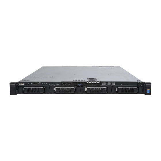
About your system The Dell PowerEdge R430 is a rack server that supports up to two processors based on the Intel Xeon EP E5-2600 v3 family, up to 12 DIMMs, and up to ten hard drives or SSDs. The R430 systems are available in the following configurations: Table 1. - Page 9 USB regular USB port or provide access to the iDRAC port features. For more information, see the Integrated Dell Remote Access Controller User’s Guide at Dell.com/idracmanuals. USB connector Allows you to connect USB devices to the system. The port is USB 2.0-compliant.
-
Page 10: Front-Panel Features And Indicators
Item Indicator, Button, or Icon Description Connector Information tag A slide-out label panel which contains system information such as Service Tag, NIC, MAC address, and so on for your reference. Hard drives Up to four 3.5 inch hot-swappable hard drives or SSDs. - Page 11 USB regular USB port or provide access to the iDRAC port features. For more information, see the Integrated Dell Remote Access Controller User’s Guide at Dell.com/idracmanuals. USB connector Allows you to connect USB devices to the system.
- Page 12 USB regular USB port or provide access to the iDRAC port features. For more information, see the Integrated Dell Remote Access Controller User’s Guide at Dell.com/idracmanuals. Diagnostic indicator The diagnostic indicator lights up to display error status. For more information, see Diagnostic indicators.
- Page 13 Figure 4. Front-panel features and indicators—four 3.5 inch cabled hard-drive chassis Table 5. Front panel features and indicators of four 3.5-inch cabled hard-drive Item Indicator, Button, or Icon Description Connector Power-on indicator, The power-on indicator lights when the system power button power is on.
-
Page 14: Lcd Panel Features
The system's LCD panel provides system information and status and error messages to indicate if the system is operating correctly or if the system needs attention. For more information on error messages, see the Dell Event and Error Messages Reference Guide at Dell.com/openmanagemanuals >OpenManage software. -
Page 15: Home Screen
SEL. This is useful when trying to match an LCD message with an SEL entry. Select Simple to view LCD error messages in a simplified user-friendly description. For more information about error messages, see the Dell Event and Error Messages Reference Guide at Dell.com/openmanagemanuals > OpenManage software. Set home Select the default information to be displayed on the Home screen. -
Page 16: Diagnostic Indicators
For more in standby, and if any error information about error messages, see the exists (for example, a failed Dell Event and Error Messages Reference fan or hard drive). Guide at Dell.com/openmanagemanuals > OpenManage software. -
Page 17: Hot Swappable Hard Drive Indicator Codes
Icon Description Condition Corrective action voltage out of range, or a on the PSU. Reseat the PSU. If the problem failed power supply unit persists, see Getting help. (PSU) or voltage regulator). Temperature The indicator flashes amber Ensure that none of the following indicator if the system experiences a conditions exist:... -
Page 18: Back-Panel Features And Indicators
NOTE: If the hard drive is in Advanced Host Controller Interface (AHCI) mode, the status indicator (on the right side) does not function and remains OFF. Table 8. Hot swappable hard drive indicators Drive-status indicator pattern (RAID only) Condition Flashes green two times per second Identifying drive or preparing for removal. - Page 19 Item Indicator, Button, or Icon Description Connector vFlash card slot Allows you to connect the vFlash card. (optional) iDRAC port (optional) Dedicated management port on the iDRAC ports card. PCIe expansion card Allows you to connect a PCI Express expansion slots (2) card.
-
Page 20: Nic Indicator Codes
Item Indicator, Button, or Icon Description Connector NOTE: For non- redundant power supply units, there is only one power supply socket. NIC indicator codes Figure 8. NIC indicators link indicator activity indicator Table 10. NIC indicators Convention Indicator pattern Description Link and activity indicators The NIC is not connected to the network. - Page 21 NOTE: For AC PSUs, use only PSUs with the Extended Power Performance (EPP) label on the back. Mixing PSUs from previous generations of Dell PowerEdge servers can result in a PSU mismatch condition or failure to turn on. Flashing amber...
-
Page 22: Non-Redundant Power Supply Unit Indicator Codes
Convention Power Indicator Condition Pattern CAUTION: When correcting a PSU mismatch, replace only the PSU with the flashing indicator. Swapping the other PSU to make a matched pair can result in an error condition and unexpected system shutdown. To change from a High Output configuration to a Low Output configuration or vice versa, you must turn off the system. -
Page 23: Documentation Matrix
Quick Resource Locator (QRL) Use the Quick Resource Locator (QRL) to get immediate access to system information and how-to videos. This can be done by visiting dell.com/QRL or by using your smartphone or tablet and a model... - Page 24 Quick Resource (QR) code located on your Dell PowerEdge system. To try out the QR code, scan the following image. Figure 11. Quick Resource Locator...
-
Page 25: Performing Initial System Configuration
Turn the system on by pressing the power button or using iDRAC. Turn on the attached peripherals. Setting up and configuring the iDRAC IP address You can set up the Integrated Dell Remote Access Controller (iDRAC) IP address by using one of the following interfaces: •... -
Page 26: Installing The Operating System
For more information, see the Integrated Dell Remote Access Controller User’s Guide at dell.com/esmmanuals. You can also remotely monitor and manage the server by using the Dell OpenManage Server Administrator (OMSA) software and OpenManage Essentials (OME) systems management console. For more information, see dell.com/openmanagemanuals. - Page 27 Download the drivers you require to a diskette drive, USB drive, CD, or DVD.
-
Page 28: Pre-Operating System Management Applications
• System Setup • Boot Manager • Dell Lifecycle Controller Navigation keys The navigation keys can help you quickly access the pre-operating system management applications. Description Enables you to enter System Setup. Enables you to enter system services and starts Lifecycle Controller. -
Page 29: About System Setup
UEFI. You can enable or disable various iDRAC parameters by using the iDRAC settings utility. For more information about this utility, see Integrated Dell Remote Access Controller User’s Guide at Dell.com/idracmanuals. Device Settings Enables you to configure device settings. -
Page 30: System Information Screen Details
Option Description Processor Settings Displays information and options related to the processor such as speed, cache size. SATA Settings Displays options to enable or disable the integrated SATA controller and ports. Boot Settings Displays options to specify the boot mode (BIOS or UEFI). Enables you to modify UEFI and BIOS boot settings. -
Page 31: Memory Settings Screen
Option Description UEFI Compliance Displays the UEFI compliance level of the system firmware. Version Memory Settings screen You can use the Memory Settings screen to view all the memory settings as well as enable or disable specific memory functions such as system memory testing and node interleaving. To view the Memory Setting screen, click System Setup Main Menu →... - Page 32 Option Description logical processor per core. By default, the Logical Processor option is set to Enabled. Alternate RTID Enables you to allocate more RTIDs to the remote socket, thereby increasing (Requestor cache performance between the sockets or easing work in normal mode for Transaction ID) NUMA.
-
Page 33: Sata Settings Screen Details
Option Description Logical Processor Enables or disables the operating system capability to put logical processors in the Idling idling state in order to reduce power consumption. By default, the option is set to Disabled. Configurable TDP Allows reconfiguration of Thermal Design Power (TDP) to lower levels. TDP refers to the maximum amount of power the cooling system is required to dissipate. - Page 34 Option Description Port A Sets the drive type of the selected device. For Embedded SATA settings in ATA mode, set this field to Auto to enable BIOS support. Set it to OFF to turn off BIOS support. For AHCI or RAID mode, BIOS support is always enabled. Option Description Model...
- Page 35 Option Description Option Description Capacity Displays the total capacity of the hard drive. This field is undefined for removable media devices such as optical drives. Port E Sets the drive type of the selected device. For Embedded SATA settings in ATA mode, set this field to Auto to enable BIOS support.
-
Page 36: Boot Settings Screen Details
Option Description For AHCI or RAID mode, BIOS support is always enabled. Option Description Model Displays the drive model of the selected device. Drive Type Displays the type of drive attached to the SATA port. Capacity Displays the total capacity of the hard drive. This field is undefined for removable media devices such as optical drives. -
Page 37: Network Settings Screen Details
Option Description CAUTION: Switching the boot mode may prevent the system from booting if the operating system is not installed in the same boot mode. If the operating system supports UEFI, you can set this option to UEFI. Setting this field to BIOS allows compatibility with non-UEFI operating systems. - Page 38 Option Description mouse operates during boot process in certain operating systems. After the boot process is complete, the USB keyboard and mouse do not work if the ports are disabled. NOTE: Selecting Only Back Ports On and All Ports Off disables the USB management port and also restricts access to iDRAC features.
-
Page 39: Serial Communication Screen Details
Serial Communication screen details You can use the Serial Communication screen to view the properties of the serial communication port. To view the Serial Communication screen, click System Setup Main Menu → System BIOS → Serial Communication. The Serial Communication screen details are explained as follows: Option Description Serial... - Page 40 Custom, the BIOS automatically sets the rest of the options. You can only change the rest of the options if the mode is set to Custom. This option is set to Performance Per Watt Optimized (DAPC) by default. DAPC is Dell Active Power Controller.
-
Page 41: System Security Settings Details
Option Description Monitor/Mwait Enables the Monitor/Mwait instructions in the processor. This option is set to Enabled for all system profiles, except Custom by default. NOTE: This option can be disabled only if the C States option in the Custom mode is set to disabled. NOTE: When C States is set to Enabled in the Custom mode, changing the Monitor/Mwait setting does not impact the system power or performance. -
Page 42: Miscellaneous Settings Screen Details
Option Description User Defined Sets the User Defined Delay option when the User Defined option for AC Power Delay (60s to Recovery Delay is selected. 240s) UEFI Variable Provides varying degrees of securing UEFI variables. When set to Standard (the Access default), UEFI variables are accessible in the operating system per the UEFI specification. -
Page 43: About Boot Manager
Option Description Keyboard Enables you to set whether the system boots with the NumLock enabled or NumLock disabled. This option is set to On by default. NOTE: This option does not apply to 84-key keyboards. F1/F2 Prompt on Enables or disables the F1/F2 prompt on error. This option is set to Enabled by Error default. -
Page 44: About Dell Lifecycle Controller
Launches System Utilities menu such as System Diagnostics and UEFI shell. About Dell Lifecycle Controller Dell Lifecycle Controller allows you to perform useful tasks such as configuring BIOS and hardware settings, deploying an operating system, updating drivers, changing RAID settings, and saving hardware profiles. -
Page 45: Assigning A System And Setup Password
NOTE: For the latest information on supported operating systems, go to dell.com/ossupport . Assigning a system and setup password Prerequisites You can assign a new System Password and Setup Password or change an existing System Password and Setup Password only when the password jumper setting is enabled and Password Status is Unlocked. -
Page 46: Deleting Or Changing An Existing System And/Or Setup Password
Steps Turn on or reboot your system. Type your password and press <Enter>. Next steps When Password Status is Locked, type the password and press <Enter> when prompted at reboot. If an incorrect system password is entered, the system displays a message and prompts you to re-enter your password. -
Page 47: Embedded System Management
NOTE: Accessing some of the features on the iDRAC Settings utility requires the iDRAC Enterprise License upgrade. For more information on using iDRAC, see the iDRAC User's Guide at dell.com/esmmanuals. Entering the iDRAC Settings utility Turn on or restart the managed system. - Page 48 Set the Maximum Air Exhaust Temperature or the Fan Speed Offset fields. Click Back → Finish → Yes.
-
Page 49: Installing And Removing System Components
Damage due to servicing that is not authorized by Dell is not covered by your warranty. Read and follow the safety instructions that came with the product. -
Page 50: After Working Inside Your System
After working inside your system Install the system cover. If applicable, install the front bezel. Reconnect the system to its electrical outlet. Turn the system on, including any attached peripherals. Related Tasks Installing the optional front bezel Installing the system cover Recommended tools You may need the following items to perform the procedures in this section: •... -
Page 51: Removing The Front Bezel
Damage due to servicing that is not authorized by Dell is not covered by your warranty. Read and follow the safety instructions that came with the product. -
Page 52: Removing The System Cover
Removing the system cover Prerequisites Ensure that you follow the Safety instructions. Turn off the system, including any attached peripherals. Disconnect the system from the electrical outlet and peripherals. If installed, remove the front bezel. Steps Turn the latch release lock to the unlock position. Lift the latch and rotate the latch toward the back of the system. -
Page 53: Installing The System Cover
Damage due to servicing that is not authorized by Dell is not covered by your warranty. Read and follow the safety instructions that came with the product. - Page 54 Figure 14. Inside the system—with a non-redundant power supply control panel cable routing latch power supply unit expansion-card riser connector (2) memory-module socket (B3, B4) processor 2 memory-module socket (B1, B2) memory-module socket (A1, A5, A2, A6) processor 1 memory-module socket (A3, A7, A4, A8) cooling fan (5) optical drive (optional)
-
Page 55: Cooling Shroud
Figure 15. Inside the System—with redundant power supplies control panel hard drive/SSD backplane cable routing latch power interposer board power supply units (2) PCIe expansion card riser (optional) memory-module socket (B3, B4) processor 2 memory-module socket (B1, B2) memory-module socket (A1, A5, A2, A6) processor 1 memory-module socket (A3, A7, A4, A8) cooling fan (6) -
Page 56: Removing The Cooling Shroud
Damage due to servicing that is not authorized by Dell is not covered by your warranty. Read and follow the safety instructions that came with the product. -
Page 57: Installing The Cooling Shroud
Damage due to servicing that is not authorized by Dell is not covered by your warranty. Read and follow the safety instructions that came with the product. - Page 58 Figure 17. System memory board Memory channels are organized as follows: Processor 1 channel 0: memory sockets A1 and A5 channel 1: memory sockets A2 and A6 channel 2: memory sockets A3 and A7 channel 3: memory sockets A4 and A8 Processor 2 channel 0: memory sockets B1 channel 1: memory sockets B2...
-
Page 59: General Memory Module Installation Guidelines
channel 3: memory sockets B4 The following table shows the memory populations and operating frequencies for the supported configurations. Table 14. Supported configurations DIMM Type DIMMs Populated/ Operating Frequency (in Maximum DIMM Rank/Channel Channel MT/s) 1.2 V RDIMM 2133, 1866, 1600, 1333 Dual rank or single rank 2133, 1866, 1600, 1333 Dual rank or single rank... -
Page 60: Sample Memory Configurations
Advanced ECC (lockstep) Advanced ECC mode extends SDDC from x4 DRAM based DIMMs to both x4 and x8 DRAMs. This protects against single DRAM chip failures during normal operation. Memory installation guidelines: • Memory modules must be identical in size, speed, and technology. •... - Page 61 System DIMM Size Number of DIMM Rank, DIMM Slot Population Capacity (in (in GB) DIMMs Organization, and Frequency 1R, x8, 2133 MT/s, A1, A2, A3, A4 1R, x8, 1866 MT/s 2R, x8, 2133 MT/s, A1, A2 2R, x8, 1866 MT/s 1R, x8, 2133 MT/s, A1, A2, A3, A4, A5, A6 1R, x8, 1866 MT/s...
-
Page 62: Removing Memory Module
Damage due to servicing that is not authorized by Dell is not covered by your warranty. Read and follow the safety instructions that came with the product. -
Page 63: Installing Memory Modules
Damage due to servicing that is not authorized by Dell is not covered by your warranty. Read and follow the safety instructions that came with the product. - Page 64 NOTE: Retain the removed memory-module blank(s) for future use. CAUTION: To prevent damage to the memory module or the memory-module socket during installation, do not bend or flex the memory module; insert both ends of the memory module simultaneously. Align the edge connector of the memory module with the alignment key of the memory module socket, and insert the memory module in the socket.
-
Page 65: Hard Drives
Damage due to servicing that is not authorized by Dell is not covered by your warranty. Read and follow the safety instructions that came with the product. -
Page 66: Installing A 2.5 Inch Hard-Drive Blank
Damage due to servicing that is not authorized by Dell is not covered by your warranty. Read and follow the safety instructions that came with the product. -
Page 67: Removing A 3.5 Inch Hard-Drive Blank
Damage due to servicing that is not authorized by Dell is not covered by your warranty. Read and follow the safety instructions that came with the product. -
Page 68: Installing A 3.5 Inch Hard-Drive Blank
Damage due to servicing that is not authorized by Dell is not covered by your warranty. Read and follow the safety instructions that came with the product. -
Page 69: Installing A Cabled Hard Drive
Damage due to servicing that is not authorized by Dell is not covered by your warranty. Read and follow the safety instructions that came with the product. -
Page 70: Removing A Hot-Swap Hard Drive
Damage due to servicing that is not authorized by Dell is not covered by your warranty. Read and follow the safety instructions that came with the product. -
Page 71: Installing A Hot-Swap Hard Drive
Damage due to servicing that is not authorized by Dell is not covered by your warranty. Read and follow the safety instructions that came with the product. -
Page 72: Installing A 2.5 Inch Hard Drive Into A 3.5 Inch Hard-Drive Adapter
Damage due to servicing that is not authorized by Dell is not covered by your warranty. Read and follow the safety instructions that came with the product. -
Page 73: Removing A 2.5 Inch Hard Drive From A 3.5 Inch Hard-Drive Adapter
Damage due to servicing that is not authorized by Dell is not covered by your warranty. Read and follow the safety instructions that came with the product. -
Page 74: Removing A Hard-Drive Adapter From A Hard-Drive Carrier
Figure 25. Removing and installing a hard-drive adapter into a 3.5 inch hard-drive carrier 3.5 inch hard-drive carrier screw (5) hard-drive adapter 2.5 inch hard drive Removing a hard-drive adapter from a hard-drive carrier Prerequisites Ensure that you read the Safety instructions. -
Page 75: Installing A Hard Drive Into A Hard-Drive Carrier
Damage due to servicing that is not authorized by Dell is not covered by your warranty. Read and follow the safety instructions that came with the product. -
Page 76: Installing An Ultra Slim Optical Drive
Damage due to servicing that is not authorized by Dell is not covered by your warranty. Read and follow the safety instructions that came with the product. -
Page 77: Removing The Standard Optical Drive
Damage due to servicing that is not authorized by Dell is not covered by your warranty. Read and follow the safety instructions that came with the product. -
Page 78: Installing The Standard Optical Drive
Damage due to servicing that is not authorized by Dell is not covered by your warranty. Read and follow the safety instructions that came with the product. -
Page 79: Cooling Fans
Damage due to servicing that is not authorized by Dell is not covered by your warranty. Read and follow the safety instructions that came with the product. -
Page 80: Installing A Cooling Fan
Damage due to servicing that is not authorized by Dell is not covered by your warranty. Read and follow the safety instructions that came with the product. -
Page 81: Internal Usb Memory Key (Optional)
Damage due to servicing that is not authorized by Dell is not covered by your warranty. Read and follow the safety instructions that came with the product. -
Page 82: Expansion Cards And Expansion-Card Risers (Optional)
Figure 30. Replacing the internal USB key USB memory key USB memory key connector Next steps Follow the procedure listed in After working inside your system. While booting, press <F2> to enter the System Setup and verify that the USB key is detected by the system. - Page 83 Expansion- PCIe slot on the Processor Height Length Link Slot width card riser expansion-card connection width riser Processor 1 Half Height Half Height NOTE: The PCIE_G3_X8 and PCIE_G3_X16 are the two different types of risers supported on R430 systems. You can install an expansion card on the system board only using expansion-card riser. NOTE: The expansion cards are not hot-swappable.
-
Page 84: Removing The Expansion-Card Riser
Damage due to servicing that is not authorized by Dell is not covered by your warranty. Read and follow the safety instructions that came with the product. -
Page 85: Installing The Expansion-Card Riser
Damage due to servicing that is not authorized by Dell is not covered by your warranty. Read and follow the safety instructions that came with the product. -
Page 86: Installing An Expansion Card
Damage due to servicing that is not authorized by Dell is not covered by your warranty. Read and follow the safety instructions that came with the product. -
Page 87: Idrac Ports Card (Optional)
Damage due to servicing that is not authorized by Dell is not covered by your warranty. Read and follow the safety instructions that came with the product. - Page 88 Figure 33. Removing and Installing the iDRAC port card iDRAC port card holder iDRAC port screw (2) SD vFlash media card iDRAC port card iDRAC port card connector Next steps Install the expansion card, if applicable. Install the expansion-card riser. Follow the procedure listed in After working inside your system.
-
Page 89: Installing The Idrac Port Card
Damage due to servicing that is not authorized by Dell is not covered by your warranty. Read and follow the safety instructions that came with the product. -
Page 90: Internal Dual Sd Module (Optional)
Damage due to servicing that is not authorized by Dell is not covered by your warranty. Read and follow the safety instructions that came with the product. -
Page 91: Installing An Internal Sd Card
Damage due to servicing that is not authorized by Dell is not covered by your warranty. Read and follow the safety instructions that came with the product. - Page 92 Figure 35. Removing and installing the Internal Dual SD Module (IDSDM) Internal Dual SD module LED status indicator (2) SD card (2) SD card slot 2 SD card slot 1 IDSDM connector The following table describes the IDSDM indicator codes: Table 20.
-
Page 93: Installing The Optional Internal Dual Sd Module
Damage due to servicing that is not authorized by Dell is not covered by your warranty. Read and follow the safety instructions that came with the product. - Page 94 Damage due to servicing that is not authorized by Dell is not covered by your warranty. Read and follow the safety instructions that came with the product.
-
Page 95: Installing The Integrated Storage Controller Card
Damage due to servicing that is not authorized by Dell is not covered by your warranty. Read and follow the safety instructions that came with the product. -
Page 96: Removing The Heat Sink
Damage due to servicing that is not authorized by Dell is not covered by your warranty. Read and follow the safety instructions that came with the product. - Page 97 Before upgrading your system, download the latest system BIOS version from dell.com/support and follow the instructions included in the compressed download file to install the update on your system. NOTE: You can update the system BIOS using the Lifecycle Controller. For more information about Dell Lifecycle controller, see dell.com/esmmanuals.
- Page 98 processor open first socket release lever unlock icon Position your thumb firmly over the processor open first socket-release lever near the unlock icon and release the lever from the locked position by pushing down and out from under the tab. Similarly, position your thumb firmly over the processor close first socket-release lever near the lock icon and release the lever from the locked position by pushing down and out from under the tab.
-
Page 99: Installing A Processor
Damage due to servicing that is not authorized by Dell is not covered by your warranty. Read and follow the safety instructions that came with the product. - Page 100 CAUTION: Positioning the processor incorrectly can permanently damage the system board or the processor. Be careful not to bend the pins in the socket. CAUTION: While removing or reinstalling the processor, wipe your hands of any contaminants. Contaminants on the processor pins such as thermal grease or oil can damage the processor.
- Page 101 Figure 39. Applying thermal grease on the top of the processor 1. processor 2. thermal grease 3. thermal-grease syringe NOTE: The thermal-grease is intended for one-time use only. Dispose of the syringe after you use it. c. Place the heat sink onto the processor. d.
-
Page 102: Installing The Heat Sink
Damage due to servicing that is not authorized by Dell is not covered by your warranty. Read and follow the safety instructions that came with the product. -
Page 103: Power Supplies
Figure 40. Applying thermal grease on the top of the processor processor thermal grease thermal grease syringe Place the heat sink onto the processor. Tighten one of the four screws to secure the heat sink to the system board. Tighten the screw diagonally opposite to the first screw you tightened. NOTE: Do not overtighten the heat sink retention screws when installing the heat sink. -
Page 104: Hot Spare Feature
NOTE: For AC power supplies, use only PSUs with the Extended Power Performance (EPP) label on the back. Mixing PSUs from previous generations of Dell PowerEdge servers can result in a PSU mismatch condition or failure to power on. -
Page 105: Installing A Redundant Power Supply
Damage due to servicing that is not authorized by Dell is not covered by your warranty. Read and follow the safety instructions that came with the product. -
Page 106: Removing A Non-Redundant Power Supply
Damage due to servicing that is not authorized by Dell is not covered by your warranty. Read and follow the safety instructions that came with the product. -
Page 107: Installing A Non-Redundant Power Supply
Damage due to servicing that is not authorized by Dell is not covered by your warranty. Read and follow the safety instructions that came with the product. -
Page 108: Removing The Power Supply Unit Blank
Next steps Follow the procedure listed in After working inside your system. Connect the power cable to the power supply and plug the cable into a power outlet. Removing the power supply unit blank If you are installing a second power supply unit, remove the power supply unit blank in the bay by pulling the blank outward. - Page 109 Damage due to servicing that is not authorized by Dell is not covered by your warranty. Read and follow the safety instructions that came with the product.
-
Page 110: Hard-Drive Backplane
Damage due to servicing that is not authorized by Dell is not covered by your warranty. Read and follow the safety instructions that came with the product. - Page 111 Figure 45. Removing and Installing the 3.5 inch or 2.5 inch (x4) SAS/SATA backplane guide (2) hard-drive/SSD backplane release tab (2) backplane power cable backplane signal cable SAS_A connector on the backplane hard-drive/SSD connector (4)
- Page 112 Figure 46. Cabling diagram—3.5 inch or 2.5 inch (x4) SAS/SATA backplane SW_RAID_A connector on the system SATA_CDROM connector on the board system board cable routing latch SAS_A connector on the backplane Optical Disk Drive (ODD) hard-drive backplane system board...
- Page 113 Figure 47. Removing and installing the 2.5 inch (x8) SAS/SATA backplane hard-drive/SSD backplane backplane power cable backplane signal cable SAS_A cable connector release tab (2) SAS_B cable connector hard-drive/SSD connector (8)
- Page 114 Figure 48. Cabling diagram—2.5 inch (x8) SAS/SATA backplane integrated storage controller card SATA_CDROM connector on the system board cable routing latch Optical Disk Drive (ODD) SAS_A connector on the backplane SAS_ B connector on the backplane hard-drive/SSD backplane system board...
- Page 115 Figure 49. Removing and installing the 2.5 inch (x10) SAS/SATA backplane hard drive/SSD backplane backplane power cable release tab (2) SAS_A connector on the backplane hard drive/SSD connector (10) SAS_B connector on the backplane SAS_C connector on the backplane...
- Page 116 Figure 50. Cabling diagram—2.5 inch (x10) SAS/SATA backplane SW_RAID_A connector on the system SW_RAID_B connector on the system board board SATA_HDD8 connector on the system SATA_HDD9 connector on the system board board cable routing latch SAS_A connector on the backplane SAS_B connector on the backplane SAS_C connector on the backplane hard drive/SSD backplane...
-
Page 117: Installing The Hard-Drive Backplane
Damage due to servicing that is not authorized by Dell is not covered by your warranty. Read and follow the safety instructions that came with the product. - Page 118 For an eight 2.5 inch hot-swappable hard-drive chassis, remove the screw (located at the bottom of the chassis) that secures the control panel to the chassis. For a ten 2.5 inch hot-swappable hard-drive chassis, Press the control panel latch and slide the control panel out of the chassis.
- Page 119 Figure 52. Removing and installing the control panel—eight 2.5 inch hard-drives/SSDs chassis control panel notches (4) control panel module LCD connector cable...
-
Page 120: Installing The Control Panel
Damage due to servicing that is not authorized by Dell is not covered by your warranty. Read and follow the safety instructions that came with the product. -
Page 121: Removing The Control-Panel Module
Damage due to servicing that is not authorized by Dell is not covered by your warranty. Read and follow the safety instructions that came with the product. - Page 122 Figure 54. Removing and installing the control-panel module—four cabled hard-drive chassis screw (2) control-panel module connector cable control panel module USB connector cable control panel LED-panel screw (2) LED panel...
- Page 123 Figure 55. Removing and installing the control panel module—four hard-drive chassis control-panel module control-panel module screws (2) control-panel module connector cable display module cable USB connector cable...
-
Page 124: Installing The Control-Panel Module
Damage due to servicing that is not authorized by Dell is not covered by your warranty. Read and follow the safety instructions that came with the product. -
Page 125: Power Interposer Board
Damage due to servicing that is not authorized by Dell is not covered by your warranty. Read and follow the safety instructions that came with the product. -
Page 126: Installing The Power Interposer Board
Damage due to servicing that is not authorized by Dell is not covered by your warranty. Read and follow the safety instructions that came with the product. -
Page 127: System Board
Damage due to servicing that is not authorized by Dell is not covered by your warranty. Read and follow the safety instructions that came with the product. - Page 128 Figure 58. Removing and installing the system board screw (9) system board system board t-handle Related Tasks Removing the cooling shroud Removing memory module Removing a cooling fan Removing an expansion card Removing the expansion-card riser Removing the integrated storage controller card Removing a processor Removing an internal SD card...
-
Page 129: Installing The System Board
Damage due to servicing that is not authorized by Dell is not covered by your warranty. Read and follow the safety instructions that came with the product. - Page 130 If the Service Tag is not backed up in the backup flash device, enter the system service tag manually. See Entering the system Service Tag using System Setup. Update the BIOS and iDRAC versions. Re-enable the Trusted Platform Module (TPM). See Re-enabling the TPM for BitLocker users orRe-enabling the TPM for TXT users.
-
Page 131: Trusted Platform Module
Import your new or existing iDRAC Enterprise license. For more information, see Integrated Dell Remote Access Controller User's Guide, at dell.com/ esmmanuals. Trusted Platform Module The Trusted Platform Module (TPM) is used to generate/store keys, protect/authenticate passwords, and create/store digital certificates. TPM can also be used to enable the BitLocker hard drive encryption feature in Windows Server. -
Page 132: Re-Enabling The Tpm For Bitlocker Users
Figure 59. Installing the TPM TPM connector slot on the TPM connector plastic bolt slot on the system board Next steps Follow the procedure listed in After working inside your system. Re-enabling the TPM for BitLocker users Initialize the TPM. For more information on initializing the TPM, see http://technet.microsoft.com/en-us/library/ cc753140.aspx. -
Page 133: Troubleshooting Your System
Damage due to servicing that is not authorized by Dell is not covered by your warranty. Read and follow the safety instructions that came with the product. -
Page 134: Troubleshooting A Serial I/O Device
If the problem is resolved, restart the system, enter the System Setup, and check if the non- functioning USB ports are enabled. Check if USB 3.0 is enabled in System Setup. If enabled, disable it and see if the issue is resolved (older operating systems may not support USB 3.0). -
Page 135: Troubleshooting A Wet System
Damage due to servicing that is not authorized by Dell is not covered by your warranty. Read and follow the safety instructions that came with the product. -
Page 136: Troubleshooting A Damaged System
Damage due to servicing that is not authorized by Dell is not covered by your warranty. Read and follow the safety instructions that came with the product. -
Page 137: Troubleshooting Power Supply Units
Damage due to servicing that is not authorized by Dell is not covered by your warranty. Read and follow the safety instructions that came with the product. -
Page 138: Troubleshooting Cooling Problems
Damage due to servicing that is not authorized by Dell is not covered by your warranty. Read and follow the safety instructions that came with the product. -
Page 139: Troubleshooting System Memory
Damage due to servicing that is not authorized by Dell is not covered by your warranty. Read and follow the safety instructions that came with the product. -
Page 140: Troubleshooting An Internal Usb Key
Damage due to servicing that is not authorized by Dell is not covered by your warranty. Read and follow the safety instructions that came with the product. -
Page 141: Troubleshooting An Optical Drive
Damage due to servicing that is not authorized by Dell is not covered by your warranty. Read and follow the safety instructions that came with the product. -
Page 142: Troubleshooting A Tape Backup Unit
Damage due to servicing that is not authorized by Dell is not covered by your warranty. Read and follow the safety instructions that came with the product. -
Page 143: Troubleshooting A Storage Controller
Damage due to servicing that is not authorized by Dell is not covered by your warranty. Read and follow the safety instructions that came with the product. -
Page 144: Troubleshooting Expansion Cards
Damage due to servicing that is not authorized by Dell is not covered by your warranty. Read and follow the safety instructions that came with the product. -
Page 145: System Messages
System messages For a list of event and error messages generated by the system firmware and agents that monitor system components, see the Dell Event and Error Messages Reference Guide at dell.com/esmmanuals. Warning messages A warning message alerts you to a possible problem and prompts you to respond before the system continues a task. -
Page 146: Using System Diagnostics
Using system diagnostics If you experience a problem with your system, run the system diagnostics before contacting Dell for technical assistance. The purpose of running system diagnostics is to test your system hardware without requiring additional equipment or risking data loss. If you are unable to fix the problem yourself, service and support personnel can use the diagnostics results to help you solve the problem. -
Page 147: System Diagnostic Controls
Displays a time-stamped log of the results of all tests run on the system. This is displayed if at least one event description is recorded. For information about embedded system diagnostics, see the ePSA Diagnostics Guide (Notebooks, Desktops and Servers) at dell.com/support/home. -
Page 148: Jumpers And Connectors
Jumpers and connectors System board jumper settings For information about resetting the password jumper to disable a password, see Disabling a Forgotten Password. Table 21. System board jumper settings Jumper Setting Description PWRD_EN The password reset feature is enabled (pins 2–4). The password reset feature is disabled (pins 4–6). -
Page 149: System Board Connectors
System board connectors Figure 60. System board jumpers and connectors Table 22. System board jumpers and connectors Item Connector Description SYS_PWR_CONN (P1) 24-pin power connector FB_USB Front-panel USB connector PIB_CONN Power interposer board connector SATA_CDROM SATA connector CDROM MiniPERC PCIE_G3_X8 (CPU1) Mini PERC card connector SATA_TBU SATA connector tape backup unit... - Page 150 Item Connector Description BATTERY Battery connector TPM_MODULE Trusted platform module connector J_PSWD_NVRAM For more information, see System board jumper settings SLOT3 PCIE_G3_X16(CPU1) PCIe card connector 3 SLOT2 PCIE_G3_X16(CPU1) PCIe card connector 2 NOTE: The PCIE_G3_X8 and PCIE_G3_X16 are the two different types of risers supported on R430 systems.
-
Page 151: Disabling A Forgotten Password
Damage due to servicing that is not authorized by Dell is not covered by your warranty. Read and follow the safety instructions that came with the product. -
Page 152: Technical Specifications
Technical specifications Table 23. Physical specifications Physical Height 42.8 mm (1.68 inch) Width With rack latches 482.4 mm (18.99 inch) Without rack latches 434.0 mm (17.08 inch) Depth (excludes bezel) 607.0 mm (23.9 inch) Weight (maximum) 19.9 kg (43.87 lb) Weight (empty) 16.73 kg (36.88 lb) Table 24. - Page 153 Memory Support for advanced ECC or memory optimized operation Memory module sockets Twelve 288-pin Memory module capacities (RDIMMs) 4 GB (single-rank), 8 GB (single- and dual-rank), 16 GB (single- and dual-rank), and 32 GB (single- and dual-rank) Minimum RAM 4 GB with single processor 8 GB with dual processor Maximum RAM Up to 192 GB with single processor...
- Page 154 Up to four 2.5-inch hot-swappable SAS, SATA, SATA SSD, or Nearline SAS hard drives. NOTE: Four hard-drive systems support software RAID. For more information on software RAID, see the Dell PowerEdge RAID Controller (PERC) documentation at dell.com/support/home. Eight hard-drive systems Up to eight 2.5-inch, hot-swappable SAS, SATA,...
- Page 155 Video memory 16 MB shared Table 32. Environmental specifications Environmental specifications NOTE: For additional information about environmental measurements for specific system configurations, see dell.com/environmental_datasheets. Temperature Storage –40°C to 65°C (–40°F to 149°F) Continuous operation (for altitude less than 950 10°C to 35°C (50°F to 95°F) with no direct m or 3117 ft) sunlight on the equipment.
- Page 156 Environmental specifications Operating Six consecutively executed shock pulses in the positive and negative x, y, and z axes of 40 G for up to 2.3 ms. Storage Six consecutively executed shock pulses in the positive and negative x, y, and z axes (one pulse on each side of the system) of 71 G for up to 2 Maximum altitude 3048 m (10,000 ft).
- Page 157 Do not perform a cold startup below 5 °C. • Allow processor performance degrade. • Non-redundant power supplies are not supported. • Non Dell qualified peripheral cards and/or peripheral cards are not supported. • Maximum altitude for the operating temperature must be 3050 m (10,000 ft).
-
Page 158: Getting Help
Documentation feedback If you have feedback for this document, write to documentation_feedback@dell.com. Alternatively, you can click on the Feedback link in any of the Dell documentation pages, fill out the form, and click Submit to send your feedback. Quick Resource Locator (QRL) Use the Quick Resource Locator (QRL) to get immediate access to system information and how-to videos. - Page 159 Figure 61. Quick Resource Locator...