Table of Contents
Advertisement
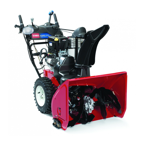
Power Max Heavy Duty 1128 OXE Snowthrower
Model No. 38828-Serial No. 313000001 and Up
Introduction
This machine is intended to be used by residential
homeowners or professional, hired operators. It is
designed primarily for removing snow from paved
surfaces, such as driveways and sidewalks, and other
surfaces for traffic on residential or commercial
properties. It is not designed for removing materials
other than snow, nor is a model with a pivoting scraper
designed for clearing off gravel surfaces.
Read this information carefully to learn how to operate and
maintain your machine properly and to avoid injury and
machine damage. You are responsible for operating the
machine properly and safely.
You may contact Toro directly at www.Toro.com for machine
and accessory information, help finding a dealer, or to register
your machine.
Whenever you need service, genuine Toro parts, or additional
information, contact an Authorized Service Dealer or Toro
Customer Service and have the model and serial numbers of
your machine ready. Figure 1 identifies the location of the
model and serial numbers on the machine. Write the numbers
in the space provided.
1. Model and serial number location
Model No.
Serial No.
This manual identifies potential hazards and has safety
messages identified by the safety alert symbol (Figure 2),
© 2012-The Toro® Company
8111 Lyndale Avenue South
Bloomington, MN 55420
Figure 1
Register at www.Toro.com.
which signals a hazard that may cause serious injury or death
if you do not follow the recommended precautions.
1. Safety alert symbol
This manual uses 2 words to highlight information.
Important calls attention to special mechanical information
and Note emphasizes general information worthy of special
attention.
Replacement Engine Owner's Manuals may be ordered
through the engine manufacturer.
Contents
Introduction .................................................................. 1
Training ................................................................. 3
Preparation............................................................. 3
Operation............................................................... 3
Maintenance and Storage.......................................... 4
Toro Snowthrower Safety ......................................... 4
Sound Pressure ....................................................... 4
Sound Power .......................................................... 4
Vibration................................................................ 4
Safety and Instructional Decals ................................. 4
Setup ............................................................................ 7
1 Installing the Upper Handle.................................... 7
2 Installing the Wheel Clutch Cable Ends .................... 8
3 Installing the Traction Control Linkage .................... 9
4 Installing the Chute Control Rod ............................10
5 Connecting the Wire to the Headlight......................11
6 Filling the Engine with Oil.....................................11
7 Checking the Tire Pressure ....................................12
8 Checking the Skids ...............................................12
9 Checking the Traction Drive Operation ...................12
Product Overview .........................................................13
Operation ....................................................................14
Filling the Fuel Tank ...............................................14
Starting the Engine .................................................14
Stopping the Engine ...............................................16
Operating the Traction Drive ...................................16
Using the Wheel Clutch Levers.................................17
Operating the Speed Selector ...................................17
Operating the Auger/Impeller Drive.........................17
Original Instructions (EN)
All Rights Reserved *3373-868* B
Printed in the USA
Form No. 3373-868 Rev B
Operator's Manual
Figure 2
Advertisement
Table of Contents

Related Manuals for Toro Power Max 1128 OXE 38828


Summary of Contents for Toro Power Max 1128 OXE 38828
-
Page 1: Table Of Contents
You are responsible for operating the attention. machine properly and safely. Replacement Engine Owner’s Manuals may be ordered You may contact Toro directly at www.Toro.com for machine through the engine manufacturer. and accessory information, help finding a dealer, or to register your machine. - Page 2 Operating the Quick Stick ® ........17 Unclogging the Discharge Chute ......18 Preventing Freeze-up ..........18 Operating Tips ............19 Maintenance ..............20 Recommended Maintenance Schedule(s) ......20 Preparing for Maintenance........21 Checking the Engine Oil Level .........21 Checking and Adjusting the Skids ......21 Checking and Adjusting the Traction Cable ....21 Checking the Auger Gearbox Oil Level ......22 Changing the Engine Oil .........22 Adjusting the Discharge Chute Latch ......23...
-
Page 3: Training
Safety safety glasses or eye shields during operation or while performing an adjustment or repair. This machine meets or exceeds the ISO standard 8437 in effect at the time of production. Operation Read and understand the contents of this manual before •... -
Page 4: Maintenance And Storage
Uncertainty Value (K) of 2 dBA. The sound power level was determined according to the Toro Snowthrower Safety procedures outlined in EN ISO 3744. The following list contains safety information specific to Toro Vibration products or other safety information that you must know. •... - Page 5 107-3040 1. Cutting dismemberment, impeller and cutting dismemberment, auger hazards—keep bystanders a safe distance from the machine. 106-4525 Reorder part no. 112-6633 1. Fast 3. Slow 2. Forward speeds 4. Reverse speeds 112-6625 Reorder part no. 112-6629 1. Cutting/dismemberment hazard, impeller—do not place your hand in the chute;...
- Page 6 Briggs & Stratton Part No. 273676 3. Fast 1. Stop 2. Slow Briggs & Stratton Part No. 277588 1. Primer 3. Ignition key out Briggs & Stratton Part No. 275949 (Engine—Stop) 1. Choke on (Choke) 2. Choke off (Run) 2. Ignition key in (Engine—Run) Briggs &...
-
Page 7: Setup
Setup Loose Parts Use the chart below to verify that all parts have been shipped. Procedure Description Qty. Handle bolts Curved washers Install the upper handle. Locknuts – No parts required Install the wheel clutch cable ends – No parts required Install the traction control linkage. -
Page 8: Installing The Wheel Clutch Cable Ends
Figure 6 1. Wheel clutch lever 3. Remove the nut and washer from the handle, attach the cable clamp on the cable to the handle, install the Figure 4 washer and the nut, and hand tighten the nut (Figure 7). Installing the Wheel Clutch Cable Ends Figure 7... -
Page 9: Installing The Traction Control Linkage
Figure 9 Note: The gap should be approximately the thickness of a pencil (1/4 inch or 6 mm). If it is greater, loosen Figure 11 the cable clamp nut, slide the cable jacket up slightly, tighten the cable clamp nut, and check the gap again. 1. -
Page 10: Installing The Chute Control Rod
Note: For easier installation, look down through the opening in the speed selector (Figure 13). g018656 Figure 14 Figure 13 1. Short rod 2. Long chute control rod 1. Speed selector 4. Insert the front end of the rod into the opening in the back of the chute gear cover until it slides into the chute gear (Figure 15). -
Page 11: Connecting The Wire To The Headlight
7. Hold the blue trigger cap down and rotate the Quick Stick in a circle to ensure that the chute and deflector operate smoothly. Filling the Engine with Oil No Parts Required Connecting the Wire to the Procedure Headlight Your machine comes with oil in the engine crankcase. Parts needed for this procedure: Note: Before starting the engine, check the oil level and add oil if necessary. -
Page 12: Checking The Tire Pressure
Checking the Traction Drive Operation No Parts Required Procedure CAUTION If the traction drive is not properly adjusted, the Figure 19 machine may move in the direction opposite of what you intended, causing injury and/or property damage. 2. Install the dipstick securely. Carefully check the traction drive and adjust it Note: Do not spill oil around the oil fill tube;... -
Page 13: Product Overview
Product Overview The machine should move forward. If the machine does not move or moves rearward, complete the following: A. Release the traction lever and stop the engine. B. Disconnect the trunnion from the speed selector lever (Figure 11). C. Turn the trunnion upward (counterclockwise) on the speed control rod (Figure 11). -
Page 14: Operation
Figure 23 1. Snow cleanout tool (attached to the handle) Operation Note: Determine the left and right sides of the machine from the normal operating position. Filling the Fuel Tank Figure 24 DANGER 1. 1-1/2 inch (3.8 cm) Gasoline is extremely flammable and explosive. A fire or explosion from gasoline can burn you and others. - Page 15 Figure 28 6. Move the throttle to the Fast position (Figure 29). Figure 26 1. Ignition key 4. Firmly push in the primer with your thumb 2 times (15°F or -9°C or above) or 4 times (below 15°F or -9°C), holding the primer in for a second before releasing it each time (Figure 27).
-
Page 16: Stopping The Engine
again). If the engine still does not start, take 5. Pull the recoil starter 3 or 4 times. This helps prevent the machine to an Authorized Service Dealer for the recoil starter from freezing up. service. 8. Disconnect the power cord from the power outlet first Operating the Traction Drive and then from the machine. -
Page 17: Using The Wheel Clutch Levers
Using the Wheel Clutch Levers The wheel clutch levers allow you to momentarily disengage the drive to one or both wheels with the traction drive lever still engaged. This enables you to turn and maneuver the machine easily. Note: Holding down the traction lever against the handle engages the traction drive to both wheels. -
Page 18: Unclogging The Discharge Chute
trigger cap to lock the discharge chute and chute deflector into position (Figure 38). Figure 40 Figure 38 Unclogging the Discharge Moving the Discharge Chute Chute Hold the blue trigger cap down and move the Quick Stick If the auger/impeller is running but there is no snow coming to the left to move the discharge chute to the left;... -
Page 19: Operating Tips
Operating Tips DANGER When the machine is in operation, the impeller and auger can rotate and cut off or injure hands and feet. • Before adjusting, cleaning, inspecting, troubleshooting, or repairing the machine, stop the engine and wait for all moving parts to stop. Disconnect the wire from the spark plug and keep it away from the plug to prevent someone from accidentally starting the engine. -
Page 20: Maintenance
• Have an Authorized Service Dealer inspect and replace the traction drive belt and/or the auger/impeller drive belt, if necessary. Important: You can find more information about maintaining and servicing your machine at www.Toro.com. Important: Refer to your engine operator's manual for additional maintenance procedures. For engine adjustments,... -
Page 21: Preparing For Maintenance
Preparing for Maintenance 1. Move the machine to a level surface. 2. Stop the engine and wait for all moving parts to stop. 3. Disconnect the spark plug wire. Refer to Replacing the Spark Plug. Figure 42 Checking the Engine Oil Level 1. -
Page 22: Checking The Auger Gearbox Oil Level
If the machine does not drive in the forward or reverse speeds or it drives when you release the traction lever, adjust the traction cable. With the traction lever disengaged, check the pin in the elongated slot in the left side of the machine above the tire. -
Page 23: Adjusting The Discharge Chute Latch
Adjusting the Discharge Chute Latch If the discharge chute does not lock into the desired position or does not unlock so that you can move it to another position, adjust the discharge chute latch. 1. Remove the fastener on the gear cover (Figure 49), lift the front of the cover up, and slide it back and out of the way. -
Page 24: Replacing The Drive Belts
If the auger/impeller drive belt or the traction drive belt (Figure 55). becomes worn, oil-soaked, or otherwise damaged, go to www.Toro.com for additional service information or have an Authorized Service Dealer replace the belt. Replacing the Headlight Bulb Use a GE 892 16W halogen light bulb. Do not touch the... -
Page 25: Storage
Storage 18. Cover the machine and store it in a clean, dry place out of the reach of children. Allow the engine to cool before storing it in any enclosure. WARNING Removing the Machine from • Gasoline vapors can explode. Storage •... -
Page 26: Troubleshooting
Troubleshooting Problem Possible Cause Corrective Action Electric starter does not turn (electric-start 1. The power cord is disconnected at the 1. Connect the power cord to the outlet models only) outlet or the machine. and/or the machine. 2. The power cord is worn, corroded, or 2. - Page 27 5. Unclog the discharge chute. 6. The auger/impeller drive belt is loose 6. Install and/or adjust the auger/impeller or is off the pulley. drive belt; refer to www.Toro.com for servicing information or take the machine to an Authorized Service Dealer.
- Page 28 Notes:...
- Page 29 Notes:...
- Page 30 The Information Toro Collects Toro Warranty Company (Toro) respects your privacy. In order to process your warranty claim and contact you in the event of a product recall, we ask you to share certain personal information with us, either directly or through your local Toro dealer.
- Page 31 Spypros Stavrinides Limited Cyprus 357 22 434131 Surge Systems India Limited India 91 1 292299901 T-Markt Logistics Ltd. Hungary 36 26 525 500 Toro Australia Australia 61 3 9580 7355 Toro Europe NV Belgium 32 14 562 960 374-0269 Rev C...
-
Page 32: Lyndale Avenue South Bloomington, Mn
Toro's option, under warranty at no cost for parts and labor. Frame failure due to misuse or abuse and failure or repair required due to rust or corrosion are not covered.