
Related Manuals for Yamaha 2009 V Star XVS650AY


Summary of Contents for Yamaha 2009 V Star XVS650AY
- Page 1 Read this manual carefully before operating this vehicle. OWNER’S MANUAL XVS650Y XVS650AY 3B7-28199-23...
- Page 2 EAU46090 Read this manual carefully before operating this vehicle. This manual should stay with this vehicle if it is sold.
- Page 3 Welcome to the Yamaha world of motorcycling! As the owner of the XVS650Y/XVS650AY, you are benefiting from Yamaha’s vast experience and newest technology re- garding the design and manufacture of high-quality products, which have earned Yamaha a reputation for dependability.
-
Page 4: Important Manual Information
IMPORTANT MANUAL INFORMATION EAU10132 Particularly important information is distinguished in this manual by the following notations: This is the safety alert symbol. It is used to alert you to potential personal injury hazards. Obey all safety messages that follow this symbol to avoid possible injury or death. - Page 5 IMPORTANT MANUAL INFORMATION EAU10200 XVS650Y/XVS650AY OWNER’S MANUAL ©2008 by Yamaha Motor Co., Ltd. 1st edition, April 2008 All rights reserved. Any reprinting or unauthorized use without the written permission of Yamaha Motor Co., Ltd. is expressly prohibited. Printed in Japan.
-
Page 6: Table Of Contents
TABLE OF CONTENTS LOCATION OF IMPORTANT Seats (XVS650AY)......4-14 Engine oil and oil filter element ..7-8 LABELS ..........1-1 Helmet holder ....... 4-15 Final gear oil ........ 7-11 Storage compartment ....4-15 Cleaning the air filter element ..7-12 SAFETY INFORMATION ....2-1 Adjusting the shock absorber Adjusting the carburetors ..... - Page 7 TABLE OF CONTENTS Checking and lubricating the sidestand ........7-24 Lubricating the swingarm pivots ...7-25 Checking the front fork ....7-25 Checking the steering ....7-26 Checking the wheel bearings ..7-26 Battery ..........7-26 Replacing the fuses ......7-28 Replacing the headlight bulb ..7-29 Replacing a turn signal light bulb or the tail/brake light bulb ..7-30 Replacing the auxiliary light bulb (XVS650AY).......7-30...
-
Page 8: Location Of Important Labels
Read and understand all of the labels on your vehicle. They contain important information for safe and proper operation of your vehicle. Never remove any labels from your vehicle. If a label becomes difficult to read or comes off, a replacement label is available from your Yamaha dealer. - Page 9 LOCATION OF IMPORTANT LABELS 3 XVS650Y 3 XVS650AY 5FB-21668-01...
-
Page 10: Safety Information
SAFETY INFORMATION EAU10283 Safe Riding • Ride where other motorists can Perform the pre-operation checks each see you. Avoid riding in another time you use the vehicle to make sure it motorist’s blind spot. Be a Responsible Owner is in safe operating condition. Failure to Many accidents involve inexperi- As the vehicle’s owner, you are respon- inspect or maintain the vehicle properly... - Page 11 SAFETY INFORMATION due to excessive speed or under- This motorcycle is designed for on- A passenger should also observe cornering (insufficient lean angle road use only. It is not suitable for the above precautions. for the speed). off-road use. • Always obey the speed limit and Avoid Carbon Monoxide Poisoning never travel faster than warrant- Protective apparel...
- Page 12 Yamaha accessories, which are avail- Shifting weights can create a sud- accessories to your motorcycle. Use able only from a Yamaha dealer, have den imbalance. Make sure that ac- extra care when riding a motorcycle been designed, tested, and approved cessories and cargo are securely that has added cargo or accessories.
- Page 13 SAFETY INFORMATION modifications not specifically recom- clearance or cornering clearance, tor and may limit control ability, mended by Yamaha, even if sold and limit suspension travel, steering therefore, such accessories are installed by a Yamaha dealer. travel or control operation, or ob- not recommended.
-
Page 14: Description
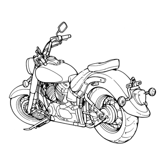
DESCRIPTION EAU10410 Left view 1. Shift pedal (page 4-8) 2. Fuel cock (page 4-11) 3. Starter (choke) knob (page 4-12) 4. Shock absorber assembly spring preload adjusting ring (page 4-16) 5. Helmet holder (page 4-15) 6. Storage compartment (page 4-15) 7. -
Page 15: Right View
DESCRIPTION EAU10420 Right view 1. Engine oil filter element (page 7-8) 2. Battery (page 7-26) 3. Fuses (page 7-28) 4. Main switch/steering lock (page 4-2) 5. Air filter element (page 7-12) 6. Brake pedal (page 4-9) -
Page 16: Controls And Instruments
DESCRIPTION EAU10430 Controls and instruments 1. Clutch lever (page 4-7) 2. Left handlebar switches (page 4-6) 3. Speedometer unit (page 4-5) 4. Fuel tank cap (page 4-9) 5. Right handlebar switches (page 4-6) 6. Throttle grip (page 7-14) 7. Brake lever (page 4-8) -
Page 17: Instrument And Control Functions
Do not expose any key to exces- a Yamaha dealer to have them re-reg- sively high temperatures. istered. Do not use the key with the red Do not place any key close to bow for driving. -
Page 18: Main Switch/Steering Lock (Xvs650Y)
INSTRUMENT AND CONTROL FUNCTIONS Keep other immobilizer system EAU10460 EAU10471 Main switch/steering lock Main switch/steering lock keys away from the main switch (XVS650Y) (XVS650AY) as they may cause signal inter- ference. The main switch/steering lock controls The main switch/steering lock controls the ignition and lighting systems, and is the ignition and lighting systems, and is used to lock the steering. - Page 19 INSTRUMENT AND CONTROL FUNCTIONS EAU10480 EWA10061 2. Push the key in from the “OFF” po- ON (XVS650Y) WARNING sition, and then turn it to “LOCK” All electrical systems are supplied with Never turn the key to “OFF” or while still pushing it. power, and the headlight, meter lighting 3.
-
Page 20: Indicator And Warning Lights
This warning light comes on or flashes if an electrical circuit monitoring the en- gine is not working correctly. If this oc- curs, have a Yamaha dealer check the self-diagnosis system. (See page 4-6 1. High beam indicator light “... -
Page 21: Speedometer Unit
Speedometer unit for a few seconds, then go off, have a Make sure there are no other immobi- Yamaha dealer check the electrical cir- lizer keys close to the main switch, and cuit. do not keep more than one immobilizer When the key is turned to “OFF”... -
Page 22: Self-Diagnosis Device
If any of those circuits are not working correctly, the engine trouble warning light will come on or flash. If this occurs, have a Yamaha dealer check the vehi- cle. ECA11170 1. Engine stop switch “ ”... -
Page 23: Clutch Lever
INSTRUMENT AND CONTROL FUNCTIONS position. To cancel the turn signal The hazard lights are used in case of EAU12820 Clutch lever lights, push the switch in after it has re- an emergency or to warn other drivers turned to the center position. when your vehicle is stopped where it might be a traffic hazard. -
Page 24: Shift Pedal (Xvs650Y)
INSTRUMENT AND CONTROL FUNCTIONS EAU12870 EAU12880 EAU12890 Shift pedal (XVS650Y) Shift pedal (XVS650AY) Brake lever 1. Shift pedal 1. Shift pedal 1. Brake lever The shift pedal is located on the left The shift pedal is located on the left The brake lever is located at the right side of the engine and is used in com- side of the engine and is used in com-... -
Page 25: Brake Pedal
INSTRUMENT AND CONTROL FUNCTIONS EAU12941 EAU13121 2. Turn the key counterclockwise to Brake pedal Fuel tank cap the original position, remove it, and then close the lock cover. XVS650Y The fuel tank cap cannot be installed unless the key is in the lock. In addition, the key cannot be removed if the cap is not properly installed and locked. -
Page 26: Fuel
WARNING bottom of the filler tube. Because Your Yamaha engine has been de- Gasoline is poisonous and can fuel expands when it heats up, signed to use regular unleaded gaso- cause injury or death. -
Page 27: Fuel Cock
INSTRUMENT AND CONTROL FUNCTIONS or premium unleaded fuel. Use of un- EAU13550 Fuel cock leaded fuel will extend spark plug life The fuel cock supplies fuel from the and reduce maintenance costs. tank to the carburetors while also filter- ing it. The fuel cock lever positions are ex- plained as follows and shown in the il- lustrations. -
Page 28: Starter (Choke) Knob
INSTRUMENT AND CONTROL FUNCTIONS This indicates reserve. With the fuel EAU13620 EAU14184 Starter (choke) knob “ ” Seats (XVS650Y) cock lever in this position, the fuel re- serve is made available. Turn the fuel Passenger seat cock lever to this position if you run out of fuel while riding. - Page 29 INSTRUMENT AND CONTROL FUNCTIONS 2. Install the passenger seat holder Tightening torque: by installing its bolts. Passenger seat nut: 3. Install the passenger seat. 13 Nm (1.3 m·kgf, 9.4 ft·lbf) Make sure that the seats are properly secured before riding. 1.
-
Page 30: Seats (Xvs650Ay)
INSTRUMENT AND CONTROL FUNCTIONS EAU14192 Tightening torque: Seats (XVS650AY) Passenger seat nut: 13 Nm (1.3 m·kgf, 9.4 ft·lbf) Passenger seat To remove the passenger seat Remove the nut and washer, and then pull the passenger seat up. 1. Bolt To install the rider seat 1. -
Page 31: Helmet Holder
INSTRUMENT AND CONTROL FUNCTIONS 2. Install the passenger seat. EAU14282 EAU14481 Helmet holder Storage compartment The storage compartment is located on Make sure that the seats are properly the left side of the vehicle. secured before riding. To open the storage compartment 1. -
Page 32: Adjusting The Shock Absorber Assembly
INSTRUMENT AND CONTROL FUNCTIONS EAU14862 2. To increase the spring preload and Adjusting the shock absorber thereby harden the suspension, assembly turn the adjusting ring in direction (a). To decrease the spring pre- load and thereby soften the sus- pension, turn the adjusting ring in direction (b). -
Page 33: Luggage Strap Holders
INSTRUMENT AND CONTROL FUNCTIONS EAU15151 EAU15301 below and have a Yamaha dealer re- Luggage strap holders Sidestand pair it if it does not function proper- The sidestand is located on the left side of the frame. Raise the sidestand or lower it with your foot while holding the vehicle upright. -
Page 34: Ignition Circuit Cut-Off System
INSTRUMENT AND CONTROL FUNCTIONS EAU15313 Ignition circuit cut-off system The ignition circuit cut-off system (com- prising the sidestand switch, clutch switch and neutral switch) has the fol- lowing functions. It prevents starting when the trans- mission is in gear and the side- stand is up, but the clutch lever is not pulled. - Page 35 WARNING With the engine turned off: 1. Move the sidestand down. If a malfunction is noted, have a Yamaha 2. Make sure that the engine stop switch is turned on. dealer check the system before riding. 3. Turn the key on.
-
Page 36: For Your Safety - Pre-Operation Checks
Failure to inspect or maintain the vehicle properly increases the possibility of an accident or equipment damage. Do not operate the vehicle if you find any problem. If a problem cannot be corrected by the procedures provided in this manual, have the vehicle inspected by a Yamaha dealer. Before using this vehicle, check the following points:... -
Page 37: Pre-Operation Check List
• Make sure that operation is smooth. • Check cable free play. Throttle grip 7-14, 7-23 • If necessary, have Yamaha dealer adjust cable free play and lubricate cable and grip housing. • Make sure that operation is smooth. Control cables 7-22 •... - Page 38 • Tighten if necessary. Instruments, lights, signals • Check operation. — and switches • Correct if necessary. • Check operation of ignition circuit cut-off system. Sidestand switch 4-17 • If system is not working correctly, have Yamaha dealer check vehicle.
-
Page 39: Operation And Important Riding Points
(See page 6-2.) The the warning light comes on or neutral indicator light should come flashes after starting, immedi- on. If not, ask a Yamaha dealer to ately stop the engine, and have check the electrical circuit. a Yamaha dealer check the self- 4. -
Page 40: Starting A Warm Engine
Starting a warm engine Shifting to “ON”, then go off, have a Follow the same procedure as for start- Yamaha dealer check the elec- XVS650Y ing a cold engine with the exception trical circuit. If the indicator light that the starter (choke) is not required flashes after starting, have a when the engine is warm. -
Page 41: Tips For Reducing Fuel Consumption
OPERATION AND IMPORTANT RIDING POINTS Shifting gears lets you control the and drive train, which are not EAU16800 Tips for reducing fuel con- amount of engine power available for designed withstand sumption starting off, accelerating, climbing hills, shock of forced shifting. Fuel consumption depends largely on etc. -
Page 42: Engine Break-In
Since the engine is brand new, do not Since the engine and exhaust immediately have a Yamaha dealer put an excessive load on it for the first system can become very hot, check the vehicle. -
Page 43: Periodic Maintenance And Adjustment
If you are not familiar with vehicle ser- If you do not have the tools or experi- vice, have a Yamaha dealer perform ence required for a particular job, have service. a Yamaha dealer perform it for you. -
Page 44: Periodic Maintenance And Lubrication Chart
From 50000 km (30000 mi), repeat the maintenance intervals starting from 10000 km (6000 mi). Items marked with an asterisk should be performed by a Yamaha dealer as they require special tools, data and technical skills. - Page 45 PERIODIC MAINTENANCE AND ADJUSTMENT ODOMETER READING ANNUAL ITEM CHECK OR MAINTENANCE JOB 1000 km 10000 km 20000 km 30000 km 40000 km CHECK (600 mi) (6000 mi) (12000 mi) (18000 mi) (24000 mi) • Check operation and adjust brake √ √...
- Page 46 PERIODIC MAINTENANCE AND ADJUSTMENT ODOMETER READING ANNUAL ITEM CHECK OR MAINTENANCE JOB 1000 km 10000 km 20000 km 30000 km 40000 km CHECK (600 mi) (6000 mi) (12000 mi) (18000 mi) (24000 mi) Brake pedal pivot • Lubricate with lithium-soap-based √...
- Page 47 PERIODIC MAINTENANCE AND ADJUSTMENT ODOMETER READING ANNUAL ITEM CHECK OR MAINTENANCE JOB 1000 km 10000 km 20000 km 30000 km 40000 km CHECK (600 mi) (6000 mi) (12000 mi) (18000 mi) (24000 mi) Moving parts and √ √ √ √ √...
-
Page 48: Removing And Installing Panels
PERIODIC MAINTENANCE AND ADJUSTMENT EAU18771 XVS650AY XVS650Y Removing and installing pan- The panels shown need to be removed to perform some of the maintenance jobs described in this chapter. Refer to this section each time a panel needs to be removed and installed. XVS650Y 1. -
Page 49: Checking The Spark Plugs
Do not attempt to 1. Spark plug cap diagnose such problems yourself. In- 2. Remove the spark plug as shown, stead, have a Yamaha dealer check with the spark plug wrench includ- the vehicle. ed in the owner’s tool kit. -
Page 50: Engine Oil And Oil Filter Element
PERIODIC MAINTENANCE AND ADJUSTMENT 3. Check each spark plug for elec- 2. Clean the surface of the spark plug EAU19744 Engine oil and oil filter ele- trode erosion and excessive car- gasket and its mating surface, and ment bon or other deposits, and replace then wipe off any grime from the The engine oil level should be checked it if necessary. - Page 51 PERIODIC MAINTENANCE AND ADJUSTMENT 3. Remove the engine oil filler cap 4. Remove the outer and inner oil fil- and drain bolt to drain the oil from ter element covers by removing the crankcase. the bolts. 1. Engine oil level check window 2.
- Page 52 PERIODIC MAINTENANCE AND ADJUSTMENT er quality than specified. In Tightening torque: addition, do not use oils labeled Engine oil drain bolt: “ENERGY CONSERVING II” or 43 Nm (4.3 m·kgf, 31 ft·lbf) higher. 9. Refill with the specified amount of Make sure that no foreign mate- the recommended oil, and then in- rial enters the crankcase.
-
Page 53: Final Gear Oil
If any 3. Install the final gear oil drain bolt, leakage is found, have a Yamaha deal- and then tighten it to the specified The oil level should be at the brim of the er check and repair the vehicle. -
Page 54: Cleaning The Air Filter Element
PERIODIC MAINTENANCE AND ADJUSTMENT 6. Check the final gear case for oil EAU33383 Cleaning the air filter element leakage. If oil is leaking, check for The air filter element should be cleaned the cause. at the intervals specified in the periodic maintenance and lubrication chart. -
Page 55: Adjusting The Carburetors
Therefore, most carbu- hose. retor adjustments should be left to a Yamaha dealer, who has the neces- sary professional knowledge and expe- rience. The adjustment described in the following section, however, may be ser- 1. -
Page 56: Adjusting The Engine Idling Speed
Yamaha dealer make the adjustment. sary, have a Yamaha dealer adjust it. 2. Check the engine idling speed and, if necessary, adjust it to spec- ification by turning the throttle stop screw. -
Page 57: Valve Clearance
XVS650AY 225 kPa (2.25 kgf/cm², 33 psi) from occurring, the valve clearance regarding the specified tires. XVS650Y 200 kPa (2.00 must be adjusted by a Yamaha dealer kgf/cm², 29 psi) at the intervals specified in the periodic Tire air pressure Rear: maintenance and lubrication chart. - Page 58 After extensive tests, only the tires list- worn-out tire. When a tire tread ed below have been approved for this begins to show crosswise lines, model by Yamaha Motor Co., Ltd. have a Yamaha dealer replace 1. Tire sidewall the tire immediately.
-
Page 59: Spoke Wheels
If any dam- the procedure, otherwise proceed as age is found, have a Yamaha follows. dealer replace the wheel. Do not attempt even the smallest repair to 3. -
Page 60: Adjusting The Brake Lever Free Play
PERIODIC MAINTENANCE AND ADJUSTMENT 5. To increase the clutch lever free EAU22093 Adjusting the brake lever free play, turn the adjusting nut in direc- play tion (a). To decrease the clutch le- ver free play, turn the adjusting nut in direction (b). 6. -
Page 61: Adjusting The Brake Pedal Position And Free Play
WARNING brake lever can indicate the sition and free play presence of air in the hydraulic It is advisable to have a Yamaha system. If there is air in the hy- dealer make these adjustments. XVS650Y draulic system, have a Yamaha... -
Page 62: Adjusting The Rear Brake Light Switch
PERIODIC MAINTENANCE AND ADJUSTMENT To increase the brake pedal free play, EAU22271 Adjusting the rear brake light turn the adjusting nut at the brake rod in switch direction (a). To decrease the brake pedal free play, turn the adjusting nut in direction (b). -
Page 63: Checking The Front Brake Pads And Rear Brake Shoes
When checking the fluid level, the wear indicator grooves. If a brake the wear limit line, have a Yamaha make sure that the top of the mas- pad has worn to the point that the wear... -
Page 64: Changing The Brake Fluid
EAU22721 EAU23101 Changing the brake fluid Checking and lubricating the brake fluid, otherwise the rubber Have a Yamaha dealer change the cables seals may deteriorate, causing brake fluid at the intervals specified in The operation of all control cables and... -
Page 65: Checking And Lubricating The Throttle Grip And Cable
PERIODIC MAINTENANCE AND ADJUSTMENT EAU23111 EAU44271 Recommended lubricant: Checking and lubricating the Checking and lubricating the Lithium-soap-based grease throttle grip and cable brake and shift pedals The operation of the throttle grip should be checked before each ride. In addi- tion, the cable should be lubricated at the intervals specified in the periodic maintenance chart. -
Page 66: Checking And Lubricating The Brake And Clutch Levers
EWA10731 WARNING If the sidestand does not move up and down smoothly, have a Yamaha dealer check or repair it. Otherwise, the sidestand could contact the ground and distract the operator, re- The operation of the brake and clutch sulting in a possible loss of control. -
Page 67: Lubricating The Swingarm Pivots
If any damage is found or the front face and hold it in an upright posi- fork does not operate smoothly, tion. WARNING! To avoid injury, have a Yamaha dealer check or re- securely support the vehicle so pair it. there is no danger of it falling over. -
Page 68: Checking The Steering
(Valve Regulated Lead Acid) battery. ward and backward. If any free There is no need to check the electro- play can be felt, have a Yamaha lyte or to add distilled water. However, dealer check or repair the steering. the battery lead connections need to be checked and, if necessary, tightened. -
Page 69: Battery
To charge the battery burns. Avoid any contact with ECA10631 Have a Yamaha dealer charge the bat- NOTICE skin, eyes or clothing and al- tery as soon as possible if it seems to ways shield your eyes when... -
Page 70: Replacing The Fuses
4. If the fuse immediately blows 6. Backup fuse (for odometer and immobilizer page 7-6.) system) (XVS650AY) again, have a Yamaha dealer If a fuse is blown, replace it as follows. 7. Spare fuse check the electrical system. 1. Turn the key to “OFF” and turn off the electrical circuit in question. -
Page 71: Replacing The Headlight Bulb
6. Install the headlight unit by install- ing the screws. 7. Have a Yamaha dealer adjust the headlight beam if necessary. 1. Headlight coupler 2. Headlight bulb cover 3. Unhook the headlight bulb holder, 1. -
Page 72: Replacing A Turn Signal Light Bulb Or The Tail/Brake Light Bulb
PERIODIC MAINTENANCE AND ADJUSTMENT EAU24283 XVS650AY EAU33413 Replacing a turn signal light Replacing the auxiliary light bulb or the tail/brake light bulb bulb (XVS650AY) 1. Remove the lens by removing the If the auxiliary light bulb burns out, re- screws. place it as follows. -
Page 73: Supporting The Motorcycle
PERIODIC MAINTENANCE AND ADJUSTMENT EAU24350 a jack either under each side of the Supporting the motorcycle frame in front of the rear wheel or under Since this model is not equipped with a each side of the swingarm. centerstand, follow these precautions when removing the front and rear wheel or performing other maintenance requiring the motorcycle to stand up-... -
Page 74: Front Wheel
PERIODIC MAINTENANCE AND ADJUSTMENT EAU24360 2. Lift the wheel up between the fork Front wheel legs. EAU24601 To remove the front wheel Make sure that there is enough space EWA10821 between the brake pads before insert- WARNING ing the brake disc and that the slot in To avoid injury, securely support the the speedometer gear unit fits over the vehicle so there is no danger of it... -
Page 75: Rear Wheel
PERIODIC MAINTENANCE AND ADJUSTMENT EAU25080 4. Remove the brake pedal free play Tightening torque: Rear wheel adjusting nut, and then disconnect Wheel axle: the brake rod from the brake cam- 59 Nm (5.9 m·kgf, 43 ft·lbf) EAU25142 shaft lever. To remove the rear wheel 6. - Page 76 PERIODIC MAINTENANCE AND ADJUSTMENT EAU25511 7. Tighten the axle nut, the final gear To install the rear wheel case bolts and the brake torque 1. Install the rear wheel, wheel axle, rod nuts to the specified torques. final gear case, and drive shaft by pushing the wheel forward and Tightening torques: guiding the drive shaft into the mid-...
-
Page 77: Troubleshooting
However, should your motorcycle require any repair, take it to a Yamaha dealer, whose skilled technicians have the necessary tools, experience, and know-how to service the motorcycle properly. -
Page 78: Troubleshooting Chart
Remove the spark plugs and check the electrodes. The engine does not start. Have a Yamaha dealer check the vehicle. Check the battery. 4. Battery The engine turns over The battery is good. -
Page 79: Motorcycle Care And Storage
Rust and corrosion can develop matte colored finished parts. Be ECA10771 even if high-quality components are sure to consult a Yamaha dealer for NOTICE advice on what products to use be- used. A rusty exhaust pipe may go un- Avoid using strong acidic wheel fore cleaning the vehicle. - Page 80 MOTORCYCLE CARE AND STORAGE cleaning products, solvent or After normal use 2. After drying the motorcycle, apply thinner, fuel (gasoline), rust re- Remove dirt with warm water, a mild a corrosion protection spray on all movers or inhibitors, brake flu- detergent, and a soft, clean sponge, metal, including chrome- and nick- id, antifreeze or electrolyte.
-
Page 81: Storage
MOTORCYCLE CARE AND STORAGE EWA11131 EAU26231 Storage WARNING Consult a Yamaha dealer for advice on Contaminants on the brakes or tires what products to use. Short-term can cause loss of control. Always store your motorcycle in a cool, Make sure that there is no oil or dry place and, if necessary, protect it wax on the brakes or tires. - Page 82 MOTORCYCLE CARE AND STORAGE 3. Drain the carburetor float cham- spark plug electrodes while °C (90 °F)]. For more information bers by loosening the drain bolts; turning the engine over. on storing the battery, see page this will prevent fuel deposits from 7-26.
-
Page 83: Specifications
SPECIFICATIONS Dimensions: Compression ratio: Air filter: 9.00 :1 Overall length: Air filter element: Starting system: XVS650AY 2450 mm (96.5 in) Dry element Electric starter XVS650Y 2340 mm (92.1 in) Fuel: Lubrication system: Overall width: Recommended fuel: Wet sump XVS650AY 930 mm (36.6 in) Unleaded gasoline only Engine oil: XVS650Y 880 mm (34.6 in) - Page 84 SPECIFICATIONS Transmission type: Rear tire: Front wheel: Constant mesh 5-speed Type: Wheel type: Operation: With tube Spoke wheel Left foot operation Size: Rim size: Gear ratio: 170/80-15M/C 77S XVS650AY 16M/C x MT3.00 1st: Manufacturer/model: XVS650Y 19M/C x MT2.50 38/14 (2.714) XVS650AY DUNLOP/D404G Rear wheel: 2nd:...
- Page 85 SPECIFICATIONS Spring/shock absorber type: High beam indicator light: 12 V, 1.7 W × 1 Coil spring/gas-oil damper Wheel travel: Turn signal indicator light: 12 V, 1.7 W × 1 XVS650AY 98.0 mm (3.86 in) XVS650Y 86.0 mm (3.39 in) Engine trouble warning light: 12 V, 1.7 W ×...
-
Page 86: Consumer Information
Yamaha EAU26400 Vehicle identification number dealer or for reference in case the vehi- cle is stolen. -
Page 87: Motorcycle Noise Regulation (For Australia)
1. Model label The model label is affixed to the frame under the rider seat. (See page 4-12.) Record the information on this label in the space provided. This information will be needed when ordering spare parts from a Yamaha dealer. 10-2... - Page 88 INDEX Air filter element, cleaning..... 7-12 Final gear oil ......... 7-11 Neutral indicator light ......4-4 Auxiliary light bulb, replacing Front fork, checking ......7-25 Noise regulation (for Australia)....10-2 (XVS650AY) ........7-30 Fuel............4-10 Fuel cock ..........4-11 Panels, removing and installing ....7-6 Fuel consumption, tips for reducing..
- Page 89 INDEX Swingarm pivots, lubricating....7-25 Throttle cable free play, checking..7-14 Throttle grip and cable, checking and lubricating ........... 7-23 Tires............7-15 Tool kit ............ 7-1 Troubleshooting........7-35 Troubleshooting chart ......7-36 Turn signal indicator light......4-4 Turn signal light bulb or tail/brake light bulb, replacing ........
- Page 92 YAMAHA MOTOR CO., LTD. PRINTED ON RECYCLED PAPER PRINTED IN JAPAN 2008.04-0.3×1 CR...