Sign In
Upload
Manuals
Brands
York Manuals
Chiller
YVAA Style A
York YVAA Style A Manuals
Manuals and User Guides for York YVAA Style A. We have
1
York YVAA Style A manual available for free PDF download: Installation Operation & Maintenance
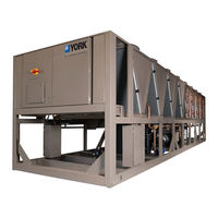
York YVAA Style A Installation Operation & Maintenance (184 pages)
Air-Cooled Screw Liquid Chiller
Brand:
York
| Category:
Chiller
| Size: 6.25 MB
Table of Contents
Table of Contents
5
Section 1 - General Chiller Information and Safety
11
Introduction
11
Warranty
11
Quality Assurance and Safety
12
Fluorinated Greenhouse Gases
12
Responsibility for Safety
12
About this Manual
12
Misuse of Equipment
12
Figure 1 - YVAA Air-Cooled Screw Liquid Chiller with Variable Speed Drives
15
Section 2 - Product Description
15
General System Description
15
Figure 2 - Chiller Control System
16
Figure 3 - View of YORK Control Center User Interface
18
Accessories and Options
19
Condenser Coils
19
Fan Options
19
Condenser
17
Electrical
17
Evaporator
17
Refrigerant Circuit
17
Semi-Hermetic YORK Twin-Screw Compressors
17
Building Automation System Capabilities
18
Microcomputer Control Center
18
Section 3 - Rigging, Handling, and Storage
23
Lifting Weights
23
Delivery and Storage
23
Inspection
24
Moving the Chiller
24
Unit Removal from Shipping Container
24
Lifting Using Lugs
24
Lifting Using Shackles
24
Figure 4 - Lifting Using Lugs
24
Table 1 - Unit Rigging
26
Section 4 - Installation
35
Location Clearances
35
Location Requirements
35
Outdoor Installations
35
Table 2 - Minimum Evaporator Tube Removal Clearance
36
Figure 5 - Acceptable Minimum Clearances Around and between Units
36
Chilled Liquid Piping
37
Shipping Braces
37
Vibration Isolators
37
Evaporator Pressure Drop
38
Figure 6 - Two Pass Water Pressure Drop, English Units
39
Figure 7 - Three Pass Water Pressure Drop, English Units
39
Figure 9 - Leaving Water Temperature out of Range Suggested Layout
40
Figure 8 - Pipework Arrangement
40
Connection Types and Sizes
41
Evaporator Connections
41
Thermal Storage
41
Variable Primary Flow
41
Leaving Water Temperature out of Range
40
Minimum Water Volume
40
Pipework Arrangement
40
Water Treatment
40
Figure 12 - Grooved Nozzle
41
Figure 13 - Flange for GB Vessels
43
Figure 14 - Flange Attachment
43
Figure 15 - Single Point Power Wiring
46
Figure 16 - Dual Point Power Wiring
47
Customer Control Wiring
48
Figure 17 - Customer Control Connections
48
Thermal Dispersion Flow Switch Connections
49
115 VAC Control Supply Transformer
44
Control Wiring
44
Power Supply Wiring
44
Power Wiring
44
System Inputs
45
Volts Free Contacts
45
Power Supply Wiring
46
Figure 11 - Suggested Layout for Applications with a Flow Rate Greater than the Evaporator Maximum
41
Figure 10 - Suggested Layout for Applications with a Flow Rate Less than the Evaporator Minimum
41
Table 3 - Evaporator Connections Dimensions
42
Electrical Connection
43
Refrigerant Relief Valve Piping
43
Figure 18 - Thermal Dispersion Flow Switch Connections
49
Figure 19 - Reserved Customer Wiring Entry
50
Figure 20 - Water Box Heater Wiring Box
50
Table 4 - Electrical Lug Data
52
Section 5 - Technical Data
63
Table 5 - Physical Data - Microchannel Coil
64
Table 6 - Physical Data - Round Tube Coil
68
Table 7 - Optional One-Pass Evaporator
70
Table 8 - Standard Two-Pass, Rear Inlet/Outlet Evaporator
74
Table 9 - Optional Three-Pass Rear Inlet/Front Outlet Evaporator
78
Figure 21 - YVAA Dimensions
82
Table 10 - Isolator Selection and Mounting Locations
84
Elastomeric Isolator Installation
90
Elastomeric Isolator Specifications
91
One Inch Deflection Isolator Installation
92
One Inch Deflection Spring Isolator Specifications
93
Two Inch Deflection Isolator Installation and Adjustment
94
Two Inch Deflection, Restrained Spring Isolator Specifications
95
Section 6 - Commissioning
97
Preparation
97
Figure 22 - LED Indicator Buttons
98
Figure 24 - Flow below the Representation Range
99
Figure 23 - Flow Switch Set
99
Figure 25 - Flow Exceeds the Representation Range
99
First Time Startup
100
General Operation
100
Table 11 - Freeze Damage Protection Requirements
101
Section 7 - Operation
103
Figure 26 - Keyboard and Display
103
Figure 27 - New 331-03478-XXX Microboard
108
Building Automation System (BAS) Communications
109
E-Link or SC-EQ Interface
110
Operating Controls
103
Basic Operating Sequence
105
Microboard (331-03478-XXX)
106
Unit Warning
106
Table 12 - Values Required for BAS Communication
111
Table 13 - Real Time Error Numbers for BAS, SC-EQ or E-Link Communications Card
112
Figure 28 - LON E-Link Gateway Option
113
SC-EQ or E-Link BAS Communications Card
113
Table 14 - YVAA Native Communications Data Map
114
Table 15 - YVAA Operational and Fault/Inhibit Codes
117
Table 16 - YVAA E-Link Communications Data Map
118
Table 17 - Flash Card Update Error XXXXX
123
Unit Safeties
125
System Safeties, Faults
126
Data Logging
123
Program Update
123
Table 18 - Low Differential Oil Pressure Cutout
128
Table 19 - Discharge Pressure Load Limiting/Unloading
129
Table 20 - Suction Pressure Load Limiting/Unloading
129
Table 21 - Start Inhibit Sensor Thresholds
130
Section 8 - Micropanel
131
Unit Data Key
134
System Data Keys 1 through 4
136
Table 22 - Sensor Min/Max Outputs
138
Table 23 - Compressor Motor Overload Settings
140
Table 24 - Setpoint Limits
150
Program Key
151
Table 25 - Programmable Operating Parameters
153
Options Key
154
Date/Time and Schedule Keys
157
Manual Override Key
160
Print Key
161
Table 26 - Printout Types
161
System Switches Key
164
Operating Hours/Start Counter Key
141
History Key
142
Setpoints Key
149
VSD Data Key
139
Section 9 - Maintenance
165
General Requirements
165
Refrigerant Removal, Evacuation and Charging a YVAA Chiller
166
Microchannel Coil Cleaning
167
Thermal Dispersion Flow Switch
168
Table 27 - Troubleshooting Guide
169
Maintenance Requirements for YVAA Chillers
170
Table 28 - R-134A Pressure to Saturated Temperature Conversion
172
Table 29 - R-513A Refrigerant Pressure to Saturated Temperature
173
Table 30 - R-513A Refrigerant Temperature to Pressure
174
Table 31 - Temperature Input Voltage Sensor (Measured Signal to Shield at the Sensor)
175
R-513A Conversion Table
176
R-513A Conversion Table
175
R-134A Conversion Table
174
Table 32 - Outside Air Temperature Sensor Input Voltage (Measured Signal to Shield at the Sensor)
176
Table 33 - Pressure Transducer Output Voltage (Measured Signal to Return at the Transducer)
177
Table 34 - Motor Temperature Sensor Resistance (Check at the Motor)
178
Section 10 - Decommissioning, Dismantling, and Disposal
181
Table 35 - si Metric Conversion
181
Temperature
182
Notes
183
Advertisement
Advertisement
Related Products
York YVWA
York YVAA
York YVAM
York YVAM1150
York YVAM1500
York YVAM1650
York YVAM0350
York YHAU-CGN-400EXS
York YCAV0457P
York YGWH 375
York Categories
Air Conditioner
Heat Pump
Chiller
Furnace
Air Handlers
More York Manuals
Login
Sign In
OR
Sign in with Facebook
Sign in with Google
Upload manual
Upload from disk
Upload from URL