Sign In
Upload
Manuals
Brands
York Manuals
Chiller
YST
York YST Manuals
Manuals and User Guides for York YST. We have
3
York YST manuals available for free PDF download: Operation Manual, Operation & Maintenance Manual, Wiring Diagrams
York YST Operation Manual (164 pages)
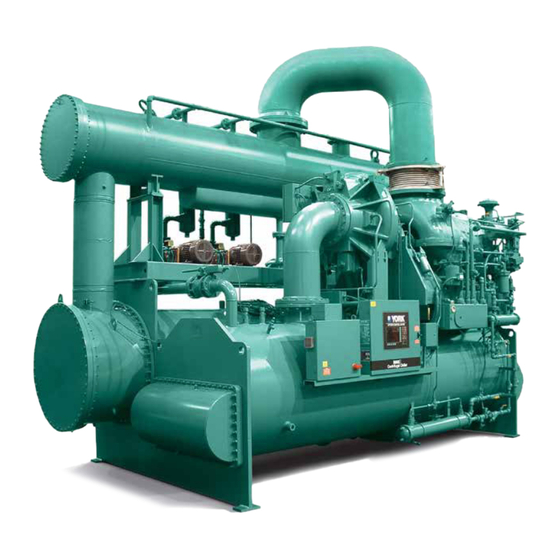
Steam Turbine Drive Centrifugal Liquid Chiller With Optiview Control Center Design Level F and G
Brand:
York
| Category:
Chiller
| Size: 5.63 MB
Table of Contents
Table of Contents
5
Figure 1 - Model YST Chiller
9
Refrigerant Flow Diagram
10
Section 1- Description of System and Fundamentals of Operation
9
General System Description
9
Refrigeration System Operation
9
Figure 2 - Refrigerant Flow-Thru
10
Figure 3 - Detail a - Compressor Pre-Rotation Vanes
11
Steam and Condensate Flow
12
Capacity Controls
11
Figure 4 - Steam and Condensate Flow
13
Section 2 - Optiview Control Center Introduction
15
Figure 5 - Optiview Control Center
16
Figure 6 - Home Screen
21
Figure 7 - Refrigeration System Screen
24
Evaporator Screen
26
Figure 8 - Evaporator Screen
26
Condenser Screen
29
Figure 9 - Condenser Screen
29
Compressor Screen
31
Figure 10 - Compressor Screen
31
Figure 11 - Proximity Probe Calibration Screen
34
Proximity Probe Calibration Screen
34
Figure 12 - Pre-Rotation Vanes Calibration Screen
36
Pre-Rotation Vanes Calibration Screen
36
Figure 13 - Oil Sump Screen
37
Oil Sump Screen
37
Figure 14 - Variable Geometry Diffuser (VGD) Screen
39
Variable Geometry Diffuser (VGD) Screen
39
[VGD] Hold (Manual)
40
Figure 15 - Variable Geometry Diffuser (VGD) Setpoints Screen
41
Variable Geometry Diffuser Setpoints Screen
41
Figure 16 - Steam System Screen - Manual Start
43
Steam System Screen - Manual Start
43
Figure 17 - Steam System Screen - Auto Start
46
Steam System Screen - Auto Start
46
Figure 18 - Turbine Screen
49
Turbine Screen
49
Condensate Screen
52
Figure 19 - Condensate Screen
52
Figure 20 - Vacuum Screen
54
Vacuum Screen
54
Capacity Controls Screen-Fixed Speed Mode
56
Figure 21 - Capacity Controls Screen-Fixed Speed Mode
56
Capacity Controls Screen-Variable Speed Mode
60
Figure 22 - Capacity Controls Screen-Variable Speed Mode
60
Pid Setup Screen 1
64
Refrigeration System Screen
24
Interface Conventions
17
Analog Input Ranges - York Microboard
19
Analog Input Ranges - Frick I/O Board
20
Home Screen
21
Figure 23 - PID Setup Screen 1
64
Figure 26 - Capacity Control Setpoints Screen 1
65
Figure 24 - PID Setup Screen 2
67
Figure 25 - Auto/Manual Screen
70
Capacity Control Setpoints Screen 1
74
Capacity Control Setpoints Screen 2
77
Figure 27 - Capacity Control Setpoints Screen 2
77
Figure 28 - Setpoints Screen
79
Setpoints Screen
79
Figure 29 - Setup Screen
81
Setup Screen
81
Figure 30 - User Screen
83
User Screen
83
Comms Screen
84
Figure 31 - Comms Screen
84
Figure 32 - Printer Screen
86
Printer Screen
86
Figure 33 - Sales Order Screen
88
Sales Order Screen
88
Display Only
90
Figure 34 - Operations Screen
90
Operations Screen
90
Alarm/Shutdown Setpoints Screen
92
Figure 35 - Alarm/Shutdown Setpoints Screen
92
Figure 36 - Time Delay Alarm/Shutdown Setpoints Screen
95
Time Delay Alarm/Shutdown Setpoints Screen
95
Configuration Screen 1
97
Figure 37 - Configuration Screen 1
97
Configuration Screen 2
99
Figure 38 - Configuration Screen 2
99
Configuration Screen 3
101
Figure 39 - Configuration Screen 3
101
Figure 40 - Pressure Setpoints Screen
103
Pressure Setpoints Screen
103
Figure 41 - Time Setpoints Screen
106
Time Setpoints Screen
106
Figure 42 - Speed Setpoints Screen
109
Speed Setpoints Screen
109
Figure 43 - Ramp Rate Setpoints Screen
112
Ramp Rate Setpoints Screen
112
Display Only
114
Figure 44 - History Screen
114
History Screen
114
Figure 45 - History Details Screen
116
History Details Screen
116
Figure 46 - Security Log Screen
117
Security Log Screen
117
Figure 47 - Security Log Details Screen
119
Security Log Details Screen
119
Custom View Screen
120
Figure 48 - Custom View Screen
120
Custom View Setup Screen
121
Figure 49 - Custom View Setup Screen
121
Figure 50 - Trend Screen
122
Trend Screen
122
Figure 51 - Trend Setup Screen
124
Trend Setup Screen
124
Advanced Trend Setup Screen
126
Figure 52 - Advanced Trend Setup Screen
126
Common Slots Screen
128
Figure 53 - Common Slots Screen
128
Master Slot Numbers List for Use with Trend Feature
129
Display Messages
131
Status Messages
131
Soft Shutdown Message
132
Start Inhibit Message
133
Warning Messages
133
Turbine Excessive Vibration Warning Messages
136
Compressor Excessive Vibration Warning Messages
138
Cycling Shutdown Messages
138
Routine Shutdown Messages
138
Safety Shutdown Messages
140
Turbine Vibration Shutdown Messages
146
Compressor Excessive Vibration Shutdown Messages
147
Auto/Manual Screen
70
PID Setup Screen 2
67
Section 3 - Printers
149
Figure 54 - Printers
149
Printers
150
Printer Connections
151
Printer Setup
151
Control Center Setup
152
Figure 55 - Sample Printout (Status)
154
Figure 56 - Sample Printout (Setpoints)
156
Figure 57 - Sample Printout (Sales Order)
158
Figure 58 - Sample Printout (History)
159
Figure 60 - Sample Printout (Trend Data New or Existing Points)
161
Figure 59 - Sample Printout (Security Log Report)
161
Figure 61 - Sample Printout (Custom Screen Report)
161
Temperature
162
Advertisement
York YST Operation & Maintenance Manual (90 pages)
STEAM TURBINE CENTRIFUGAL LIQUID CHILLERS
Brand:
York
| Category:
Chiller
| Size: 4.1 MB
Table of Contents
Table of Contents
5
FIGURE 1 - Model YST Chiller
11
Capacity Controls
12
Refrigeration System Operation
12
Section 1 - Description of System and Fundamentals of Operation
11
General System Description
11
FIGURE 2 - Compressor Prerotation Vanes
12
FIGURE 3 - Refrigerant Flow - Thru
14
Steam and Condensate Flow
15
FIGURE 4 - Steam and Condensate Flow
16
FIGURE 5 - Steam Condenser Hotwell Level Switches
17
Section 2 - Pre-Startup and System Operating Procedures
19
Blow-Down the Inlet Steam Line
19
Check the Status of the Main Steam Supply
19
Overview
19
Pre-Startup Procedures - Initial and after Long Term Shutdown
19
Flush the Turbine Lube System (Pressure Lubrication Turbine Only)
20
Inspect and Clean Steam Strainers
20
Inspect and Clean the Turbine
20
Inspect and Clean Water Strainers
20
Check the Coupling and Alignment
21
Check the Oil Level in the Turbine Bearing Reservoirs (Ring Oil Lubrication)
21
Check the Refrigerant Charge
21
Oil Heater Operation
21
Oil Heaters
21
Check the Oil Level in the Compressor Oil Reservoir
22
Check the Status of All Utilities
22
Verify the Compressor Oil Pump Operation
22
Verify the Turbine Governor Valve Operation
22
Prepare the Steam Condenser Hotwell and Pumps
23
Verify the Compressor Pre-Rotation Vane Operation
23
Verify the Hot Gas Bypass and Subcooler Level Control Valve Operation
23
Prepare the Steam Condenser Vacuum Pumps
24
Pre-Startup Procedures - after Short Term Shutdown
25
Prepare the Chilled and Condenser Water Piping and Pumps
25
Prepare the Pressure Powered Pump
25
Prepare the Steam Condenser Atmospheric Relief Valve
25
Verify All User Defined Setpoints
25
FIGURE 6 - Slow Roll Time Calculation
26
Sequence of Operation
26
Overview
27
Slow Roll Time Calculation
27
FIGURE 7 - Operation Sequence Timing Diagram (Manual Start)
29
FIGURE 8 - Operation Sequence Timing Diagram (Automatic Start)
30
FIGURE 9 - Liquid Chiller Log Sheets
44
FIGURE 10 - System Components
49
Compressor Lubrication System
50
Compressor Variable Geometry Diffuser (VGD)
50
General
50
Monthly
45
Pressure Lubrication
45
Quarterly
45
Ring Oil Lubrication
45
Weekly
45
Annually (more Often if Necessary)
46
Need for Maintenance or Service
46
Semi-Annually (or more Often as Required)
46
Year
46
Prolonged Shutdown
47
Turbine Off-Season Storage
47
Turbine Steam Path
47
Other Recommendations
48
Steam Condenser Off-Season Storage
48
Turbine Lubrication System
48
System Shutdown
47
Startup Sequence of Operation
31
System Operating Procedure
35
General
35
Hourly
35
Shut down Sequence of Operation
36
Normal (Controlled) Stop
36
Immediate Stop
36
Post Trip Shutdown Sequence
36
Capacity Controls
38
Overview
38
Fixed Speed Chiller Capacity Controls Operation
38
Fixed Speed Chiller Loading Sequence
38
Fixed Speed Chiller Override Controllers
39
High and Low Refrigerant Pressure
39
Turbine Governor Position Power Limiting
40
Turbine Horsepower Limiting
40
Fixed Speed Chiller Unloading Sequence
39
PRV Control
39
Hot Gas Ratio Control
39
HGV Temperature Controller
39
Variable Speed Chiller Capacity Controls Operation
40
Variable Speed Chiller Loading Sequence
41
Hot Gas Mode
41
PRV Mode
41
Speed Mode
41
Variable Speed Chiller Unloading Sequence
41
PRV Mode
42
Hot Gas Mode
42
Variable Speed Chiller Override Controllers
42
High and Low Refrigerant Pressure
42
Turbine Governor Position Power Limiting
42
Turbine Horsepower Limiting
43
Operating Log Sheet
43
Operating Inspections
44
Daily
44
Section 3 - System Components Description
49
FIGURE 11 - Schematic Drawing - (YST) Compressor Lubrication System
51
FIGURE 12 - KD & KG Turbine Drawing
54
FIGURE 13 - Overspeed Protection Knob Assembly
60
Atmospheric Relief Valve
61
Power Panel
61
Steam Condenser
61
Steam Condenser Package
61
Hotwell (Condensate) Pump
62
Level Control
62
Vacuum Pump
62
FIGURE 14 - Oil Return System
63
Compressor Oil Charging Procedure
64
The Compressor Oil Charge
64
KD Steam Turbine with External Pressurized Lube System
55
KD Turbine Auxiliary Oil Pump
55
KG Steam Turbine with Ring Oil Lubrication
55
Turbine Gland Seal System
55
Types of Gland Leak-Off Systems
55
Gland Seal Leak-Off Piping
56
Gland Seal System: Standard YST Condensing Turbines
56
Gland Seal Wear
56
Gland Leak-Off Condenser - Optional Supply by Special Quotation
57
Sentinel Warning Valve
57
Steam Nozzle Valves
57
Steam Ring Drain
57
Vacuum Breaker Solenoid Valve
57
Condensate Drain Tank - Optional Supply by Special Quotation
58
Installation Is Provided by Others
58
Pressure Powered Condensate Drain Pump
58
Heat Exchangers
59
Turbine Governor and Overspeed Controls
59
Hot Gas Bypass
60
Optional Service Isolation Valves
60
Optiview™ Control Center
60
Refrigerant Flow Control
60
Compressor OIL HEATER
52
Compressor Oil Pump
52
Steam Turbine
52
Steam Turbine Inlet Valves
53
Turbine Bearings
53
Turbine Lubrication Systems
53
Section 4 - Operational Maintenance
63
Changing the Dehydrator
63
Compressor Oil Return System
63
FIGURE 15 - Charging Oil Reservoir with Oil
64
FIGURE 16 - Standard Single Oil Filter and Optional Dual Oil Filter
65
Dual Oil Filter Replacement
66
Turbine Oil Maintenance
66
Ring Oil Lubrication
66
Compressor Oil Filter
65
Single Oil Filter Replacement
65
TABLE 1 - Recommended Maximum Turbine Bearing, Oil Sump, and Metal Temperatures
66
TABLE 2 - Refrigerant Charge Level
68
Pressure Connections
69
Refrigerant Charging
69
Refrigerant Leak Checking
69
FIGURE 17 - Dual Oil Filter Isolation Valve
66
Pressure Lubrication
67
Determining Correct Refrigerant Charge Level
68
Lube Oil Flushing
68
Section 5 - Troubleshooting
71
TABLE 3 - Operation Analysis Chart
71
Section 6 - Maintenance
73
Checking System for Leaks
73
Leak Testing During Operation
73
Evacuation and Dehydration of Unit
73
FIGURE 18 - Evacuation of Chiller
73
Renewal Parts
73
TABLE 4 - System Pressures
73
FIGURE 19 - Saturation Curve
75
Checking the Refrigerant Charge During Unit Shutdown
76
Chemical Water Treatment
76
Cleaning Evaporator and Condenser Tubes
76
Condenser
76
Evaporator
76
Handling Refrigerant for Dismantling and Repairs
76
Refrigerant Condensers and Evaporators
76
General
76
Tube Fouling
76
Commercial Acid Cleaning
77
Testing for Evaporator and Condenser
77
Tube Leaks
77
Tube Cleaning Procedures
77
Acid Cleaning of Tubes
77
Brush Cleaning of Tubes
77
Compressor Maintenance
78
Steam Condenser Condensate Pump Maintenance
78
Steam Condenser Vacuum Pump Maintenance
78
Turbine Internal Inspection
78
Check the Casing Interior for Foreign Material before Closing
80
Electrical Controls
80
Conducting R-22 Pressure Test
74
Vacuum Dehydration
74
Vacuum Testing
74
Operation
75
Refrigerant Charging
75
TABLE 5 - Turbine Tightening Torques (Without Washers)
80
TABLE 6 - Turbine Tightening Torques (with Washers)
80
Section 7 - Preventive Maintenance
81
Compressor
81
Electrical Controls
81
Evaporator and Refrigerant Condenser
81
Leak Testing
81
Oil Return System
81
Detection of Corrosion
86
Detection of Deposits
86
Effects of Deposits and Harmful Ions on Turbine
86
Steam Purity
86
Steam Purity/Turbine Deposits
86
Overview
86
TABLE 7 - Recommended Limits for Boiler Water (Based on Drum Water Analyses)
87
Temperature
88
TABLE 8 - si Metric Conversion
88
Notes
89
York YST Wiring Diagrams (30 pages)
STEAM TURBINE DRIVE CENTRIFUGAL CHILLER WITH OPTIVIEW CONTROL CENTER
Brand:
York
| Category:
Chiller
| Size: 2.94 MB
Table of Contents
Read before Proceeding
2
General Safety Guidelines
2
Safety Symbols
2
Changeability of this Document
3
Elementary Diagram
8
Advertisement
Advertisement
Related Products
YORK YS
York YS Series
York YCAL0019EE
York YHAU-CGH-700EXH
York MILLENNIUM YCAS0403
York YCAV0417V
York MILLENNIUM YCAS 250
York YLAA0142HE
York YHAU-CGH-560EXH
York YCAL0042EB
York Categories
Air Conditioner
Heat Pump
Chiller
Furnace
Air Handlers
More York Manuals
Login
Sign In
OR
Sign in with Facebook
Sign in with Google
Upload manual
Upload from disk
Upload from URL